Page 17 of 37
44-19
Wheel alignment, mandatory sequence
of operations for checking
Overview of sequence of operations for
measuring wheel alignment
Vehicle must only be measured at curb
weight
Note:
Exception: when measuring the toe-in curve as
described in the alignment program instructions.
The following work sequences must be
adhered to
1 - Check front axle camber centering and
adjust if necessary page 44
-24
.
2 - Check rear axle camber and adjust if
necessary:
FWD vehicles page 44
-20
AWD vehicles page 44
-22
3 - Check rear axle and adjust if necessary:
Pa
ge 17 of 37 Wheel ali
gnment
11/19/2002 htt
p://127.0.0.1:8080/audi/servlet/Dis
play?action=Goto&t
yp
e=re
pair&id=AUDI.B5.SU01.44.2
Page 18 of 37
FWD vehicles page 44
-21
AWD vehicles page 44
-23
4 - If necessary, check toe-in curve on front
axle.
To determine if the toe-in curve or toe
constant "S" needs adjusting table on
page 44
-10
and also page Page 44
-27
.
5 - Check front axle toe with vehicle at curb
weight and adjust if necessary page 44
-38
.
Pa
ge 18 of 37 Wheel ali
gnment
11/19/2002 htt
p://127.0.0.1:8080/audi/servlet/Dis
play?action=Goto&t
yp
e=re
pair&id=AUDI.B5.SU01.44.2
Page 19 of 37
44-20
Rear axle camber (front-wheel-drive
vehicles), checking
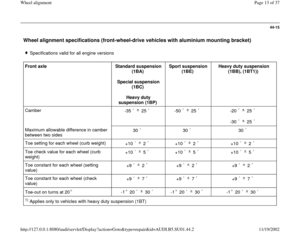
Wheel alignment specifications page 44
-11
.
The rear axle camber can be checked but not
adjusted on vehicles with front wheel drive.
If the readings are outside the allowable
tolerances the axle beam must be checked for
damage and replaced if necessary.
Pa
ge 19 of 37 Wheel ali
gnment
11/19/2002 htt
p://127.0.0.1:8080/audi/servlet/Dis
play?action=Goto&t
yp
e=re
pair&id=AUDI.B5.SU01.44.2
Page 20 of 37
44-21
Rear axle toe (front-wheel-drive
vehicles), centering
Individual toe settings on the rear axle cannot be
adjusted.
By moving the rear axle within the elongated
holes it is possible to center the individual toe
settings.
- Loosen securing bolts on mounting brackets.
- Center individual toe settings by moving axle
beam within elongated holes at mounting
brackets.
If the overall toe setting is outside the allowable
tolerance, or if it is not possible to center the
individual settings, the axle beam must be
checked for damage and replaced if necessary.
The body alignment must also be
checked/measured in the area of the rear axle
mounting points and serviced as necessary.
Repair Manual, Body Collision Repair
Pa
ge 20 of 37 Wheel ali
gnment
11/19/2002 htt
p://127.0.0.1:8080/audi/servlet/Dis
play?action=Goto&t
yp
e=re
pair&id=AUDI.B5.SU01.44.2
Page 21 of 37
44-22
Rear axle camber (all-wheel-drive
vehicles), adjusting
Wheel alignment specifications page 44
-13
Note:
The maximum adjustment range is 90 to the left or right of the center
position. - Loosen mounting nuts -1-.
- Adjust camber by turning eccentric bolt.- Tighten mounting nut, check camber again and if necessary re-adjust.
Pa
ge 21 of 37 Wheel ali
gnment
11/19/2002 htt
p://127.0.0.1:8080/audi/servlet/Dis
play?action=Goto&t
yp
e=re
pair&id=AUDI.B5.SU01.44.2
Page 22 of 37
44-23
Rear axle toe (all-wheel-drive vehicles),
setting
Wheel alignment specifications page 44
-13
- Loosen mounting nut -1-.
Notes:
The maximum adjustment range is 90 to the
left or right of the center position.
Adjusting the individual toe settings
automatically alters the thrust angle of the axle.
- Adjust individual toe settings as necessary by turning eccentric bolt.
- Tighten mounting nut, check settings again and if necessary re-adjust.
Pa
ge 22 of 37 Wheel ali
gnment
11/19/2002 htt
p://127.0.0.1:8080/audi/servlet/Dis
play?action=Goto&t
yp
e=re
pair&id=AUDI.B5.SU01.44.2
Page 23 of 37
44-24
Front axle camber, adjusting
The camber cannot be adjusted.
By moving the subframe it is possible to center
the camber uniformly within the specified
tolerance range.
- Remove noise insulation panel.
- Remove bolts -3- and -4-.
- Install VAG1941 camber adjustment tool.
Tightening torque of bolts -1-: 10 Nm (7 ft lb)
Pa
ge 23 of 37 Wheel ali
gnment
11/19/2002 htt
p://127.0.0.1:8080/audi/servlet/Dis
play?action=Goto&t
yp
e=re
pair&id=AUDI.B5.SU01.44.2
Page 24 of 37
44-25
- Loosen bolts -1-, -2-, -5-, -6-, -7- and -8-.
Wheel alignment specifications page 44
-13
. - Turn bolt -2- until specifications are achieved.
- Relieve tension on bolt -2- and check readings obtained. If necessary,
correct camber again.
Pa
ge 24 of 37 Wheel ali
gnment
11/19/2002 htt
p://127.0.0.1:8080/audi/servlet/Dis
play?action=Goto&t
yp
e=re
pair&id=AUDI.B5.SU01.44.2


, checking
Wheel alignment specifications page 44
-11
.
The rear axle camber can be checked but not
adjusted on vehicles")
, centering
Individual toe settings on the rear axle cannot be
adjusted.
By moving the rear axle within the elongated
holes it")
, adjusting
Wheel alignment specifications page 44
-13
Note:
The maximum adjustment range is 90 to the left or right of t")
,
setting
Wheel alignment specifications page 44
-13
- Loosen mounting nut -1-.
Notes:
The maximum adjustment")

