Page 112 of 381

3 - 43
CHK
ADJLUBRICATING THE DRIVE CHAIN/
CHECKING AND ADJUSTING THE STEERING HEAD
EB304100
LUBRICATING THE DRIVE CHAIN
The drive chain consists of many interact-
ing parts. If the drive chain is not main-
tained properly, it will wear out rapidly.
Therefore, the drive chain should be ser-
viced, especially when the motorcycle is
used in dusty areas. This motorcycle has a
drive chain with small rubber O-rings
between each side plate. Steam cleaning,
high-pressure washing, certain solvents,
and the use of a coarse brush can damage
these O-rings. Therefore, use only kerosine
to clean the drive chain. Wipe the drive
chain dry and thoroughly lubricate it with
engine oil or chain lubricant that is suitable
for O-ring chains. Do not use any other
lubricants on the drive chain since they may
contain solvents that could damage the O-
rings.
Recommended lubricant
Engine oil or chain lubricant
suitable for O-ring chains
EB304130
CHECKING AND ADJUSTING THE
STEERING HEAD
1. Stand the motorcycle on a level surface.
WARNINGWARNING
Securely support the motorcycle so that
there is no danger of it falling over.
NOTE:
Place the motorcycle on a suitable stand
so that the front wheel is elevated.
2. Check:
• steering head
Grasp the bottom of the front fork legs
and gently rock the front fork.
Looseness/binding ® Adjust the steer-
ing head.
Page 115 of 381

3 - 46
CHK
ADJCHECKING AND ADJUSTING THE STEERING HEAD/
CHECKING THE FRONT FORK
d. Hold the spring gauge at a 45˚ angle
from the handlebar, pull the spring
gauge, and record the measurement
when the handlebar starts to turn.
e. Repeat the above procedure on the
opposite handlebar.
f. If the steering head tension is out of
specification (both handlebars should
be within specification), remove the
upper bracket and loosen or tighten
the upper ring nut.
g. Reinstall the upper bracket and mea-
sure the steering head tension again
as described above.
h. Repeat the above procedure until the
steering head tension is within speci-
fication.
i. Grasp the bottom of the front fork
legs and gently rock the front fork.
Looseness or binding ® Adjust the
steering head.
s s s s s s s s s s s s s s s s s s s s s s s s s s s
Steering head tension
200 ~ 500 g (7.06 ~ 17.65 oz)
EB304141
CHECKING THE FRONT FORK
1. Stand the motorcycle on a level surface.
WARNINGWARNING
Securely support the motorcycle so that
there is no danger of it falling over.
2. Check:
• inner tube 1
Damage/scratches ® Replace.
• dust seal 2
• oil seal
Oil leakage ® Replace.
3. Hold the motorcycle upright and apply
the front brake.
4. Check:
• front fork operation
Push down hard on the handlebars
several times and check if the front
fork rebounds smoothly.
Rough movement ® Repair.
Refer to “FRONT FORK” in chapter 7.
Page 120 of 381

3 - 51
CHK
ADJ
CHECKING THE TIRES
EB304170
CHECKING THE TIRES
The following procedure applies to both of
the tires.
1. Measure:
• tire pressure
Out of specification ® Regulate.
WARNINGWARNING
• The tire pressure should only be
checked and regulated when the tire
temperature equals the ambient air
temperature.
• The tire pressure and the suspension
must be adjusted according to the
total weight (including cargo, rider,
passenger and accessories) and the
anticipated riding speed.
• Operation of an overloaded motorcy-
cle could cause tire damage, an acci-
dent or an injury.
NEVER OVERLOAD THE MOTORCYCLE.
* total of cargo, rider and accessories
WARNINGWARNING
It is dangerous to ride with a worn-out
tire. When the tire tread reaches the
wear limit, replace the tire immediately.Basic weight
(with oil
and a full
fuel tank)207 kg (456 lb)
Maximum
load*317 kg (699 lb)
Cold tire
pressureFront Rear
Up to 90 kg
(198 lb)
load*250 kPa
(2.5 kgf/cm
2,
36 psi)250 kPa
(2.5 kgf/cm2,
36 psi)
90 kg (198 lb)
~ maximum
load*250 kPa
(2.5 kgf/cm
2,
36 psi)290 kPa
(2.9 kgf/cm2,
41 psi)
High-speed
riding250 kPa
(2.5 kgf/cm
2,
36 psi)250 kPa
(2.5 kgf/cm2,
36 psi)
Page 123 of 381

3 - 54
CHK
ADJ
EB304200
CHECKING AND LUBRICATING THE
CABLES
The following procedure applies to all of
the cable sheaths and cables.
WARNINGWARNING
Damaged cable sheaths may cause the
cable to corrode and interfere with its
movement. Replace damaged cable
sheaths and cables as soon as possible.
1. Check:
• cable sheath
Damage ® Replace.
2. Check:
• cable operation
Rough movement ® Lubricate.
NOTE:
Hold the cable end upright and pour a
few drops of lubricant into the cable
sheath or use a suitable lubing device.
EB304210
LUBRICATING THE LEVERS AND PEDALS
Lubricate the pivoting point and metal-to-
metal moving parts of the levers and ped-
als.
EB304220
LUBRICATING THE SIDESTAND
Lubricate the pivoting point and metal-to-
metal moving parts of the sidestand.
EB304240
LUBRICATING THE REAR SUSPENSION
Lubricate the pivoting point and metal-to-
metal moving parts of the rear suspension.
Recommended lubricant
Engine oil or a suitable cable
lubricant
Recommended lubricant
Lithium soap base grease
Recommended lubricant
Lithium soap base grease
Recommended lubricant
Molybdenum disulfide grease
CHECKING AND LUBRICATING THE CABLES/
LUBRICATING THE LEVERS AND PEDALS/LUBRICATING THE
SIDESTAND/LUBRICATING THE REAR SUSPENSION
Page 124 of 381

3 - 55
CHK
ADJ
EB305020
ELECTRICAL SYSTEM
CHECKING AND CHARGING THE BATTERY
WARNINGWARNING
Batteries generate explosive hydrogen
gas and contain electrolyte which is
made of poisonous and highly caustic
sulfuric acid.
Therefore, always follow these preven-
tive measures:
• Wear protective eye gear when han-
dling or working near batteries.
• Charge batteries in a well-ventilated
area.
• Keep batteries away from fire, sparks
or open flames (e.g., welding equip-
ment, lighted cigarettes).
• DO NOT SMOKE when charging or
handling batteries.
• KEEP BATTERIES AND ELECTROLYTE
OUT OF REACH OF CHILDREN.
• Avoid bodily contact with electrolyte
as it can cause severe burns or perma-
nent eye injury.
FIRST AID IN CASE OF BODILY CON-
TACT:
EXTERNAL
• Skin – Wash with water.
• Eyes – Flush with water for 15 minutes
and get immediate medical attention.
INTERNAL
• Drink large quantities of water or milk
followed with milk of magnesia,
beaten egg or vegetable oil. Get
immediate medical attention.
ACHTUNG:CAUTION:
• This is a sealed battery. Never remove
the sealing caps because the balance
between cells will not be maintained
and battery performance will deterio-
rate.
• Charging time, charging amperage
and charging voltage for an MF bat-
tery are different from those of con-
ventional batteries. The MF battery
should be charged as explained in the
charging method illustrations. If the
battery is overcharged, the electrolyte
level will drop considerably. There-
fore, take special care when charging
the battery.
CHECKING AND CHARGING THE BATTERY
Page 131 of 381
3 - 62
CHK
ADJ
REPLACING THE HEADLIGHT BULBS
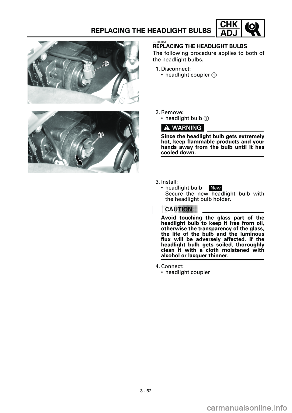
EB305051
REPLACING THE HEADLIGHT BULBS
The following procedure applies to both of
the headlight bulbs.
1. Disconnect:
• headlight coupler 1
1�
1�
2. Remove:
• headlight bulb 1
WARNINGWARNING
Since the headlight bulb gets extremely
hot, keep flammable products and your
hands away from the bulb until it has
cooled down.
1�
1�
3. Install:
• headlight bulb
Secure the new headlight bulb with
the headlight bulb holder.
ACHTUNG:CAUTION:
Avoid touching the glass part of the
headlight bulb to keep it free from oil,
otherwise the transparency of the glass,
the life of the bulb and the luminous
flux will be adversely affected. If the
headlight bulb gets soiled, thoroughly
clean it with a cloth moistened with
alcohol or lacquer thinner.
4. Connect:
• headlight coupler
New
Page 134 of 381
ENG
4 - 2
ENGINE
T R..70 Nm (7.0 m • kg, 50 ft • Ib)
T R..10 Nm (1.0 m • kg, 7.2 ft • Ib)
T R..10 Nm (1.0 m • kg, 7.2 ft • Ib)
LTLT
1 3
2 1314
128 5 46791110
1
New
Order Job/Part Q’ty Remarks
8 Speed sensor 1
9 Drive sprocket cover 1
10 Oil seal support plate 1
11 Dowel pin 2
12 Push rod #2 1
13 Lock washer 1
14 Drive sprocket 1
For installation, reverse the removal
procedure.
4
Page 136 of 381
ENG
4 - 4
ENGINE
Order Job/Part Q’ty Remarks
Disconnecting the leads and hoses
Disconnect the parts in the order listed.
Fuel tank and air filter case cover Refer to “FUEL TANK AND AIR FILTER
COVER” in chapter 3.
Air filter case and throttle body
assemblyRefer to “ELECTRONIC FUEL INJEC-
TION” in chapter 6.
Engine oil and oil filter cartridge Drain.
Refer to “CHANGING THE ENGINE
OIL” in chapter 3.
Oil cooler and thermostat assembly Refer to “OIL COOLER” and “THER-
MOSTAT ASSEMBLY” in chapter 5.
1 Battery negative lead 1
2 Battery positive lead 1
ACHTUNG:CAUTION:
First, disconnect the negative lead,
then the positive lead.

T R..10 Nm (1.0 m • kg, 7.2 ft • Ib)
T R..10 Nm (1.0 m • kg, 7.2 ft • Ib)
LTLT
1 3
2 1314
128 5 46791110
1
New
Order Job/Part Q’")
