Page 337 of 381
8 - 1
–+ELEC
ELECTRICAL COMPONENTS
EB800000
ELECTRICAL
ELECTRICAL COMPONENTS
1
Wire harness
2
Main switch
3
Front brake light switch
4
Ignition coils
5
Clutch switch
6
Throttle position sensor
7
Intake air temperature sensor
8
Intake air pressure sensor
9
Atmospheric pressure sensor
0
Turn signal relay
A
Relay unit
B
ECU
C
CDI unit
D
Fuse box
E
Fall detection switch
F
Starter relay
G
Main fuse
H
Main relay
I
Battery
J
Rectifier/regulator
K
Rear brake light switch
L
Neutral switch
M
Speed sensor
N
Sidestand switch
O
Stator coil assembly
P
Oil level switch
Q
Pickup coil
R
Radiator fan
S
Horn
T
Coolant temperature
sender
U
Thermo switch
V
Camshaft sensor
8
Page 338 of 381

8 - 2
–+ELEC
SWITCHES
EB801000
SWITCHES
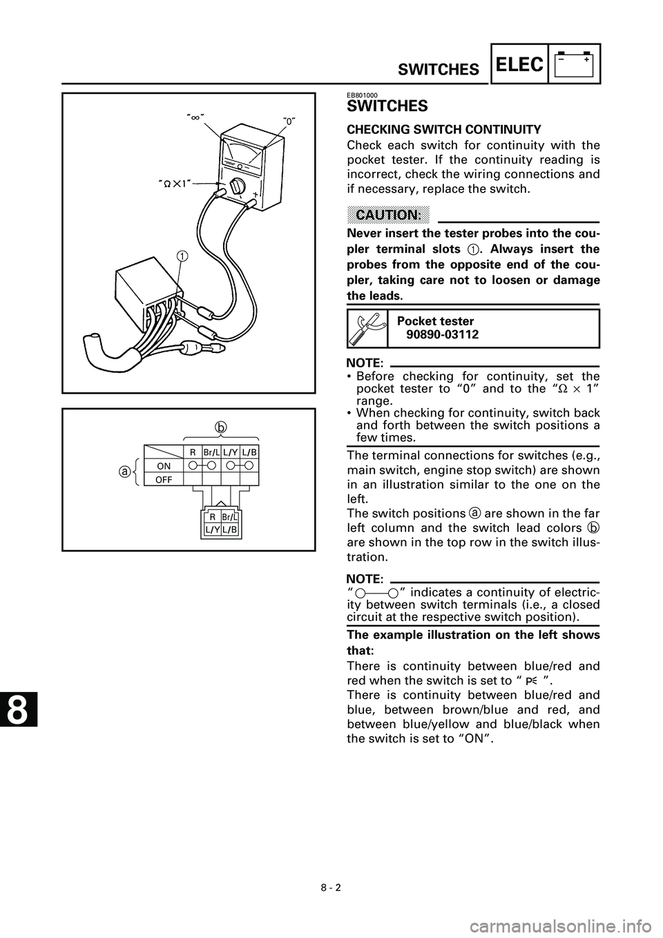
CHECKING SWITCH CONTINUITY
Check each switch for continuity with the
pocket tester. If the continuity reading is
incorrect, check the wiring connections and
if necessary, replace the switch.
CAUTION:
Never insert the tester probes into the cou-
pler terminal slots
1
. Always insert the
probes from the opposite end of the cou-
pler, taking care not to loosen or damage
the leads.
NOTE:
• Before checking for continuity, set the
pocket tester to “0” and to the “
W
´
1”
range.
• When checking for continuity, switch back
and forth between the switch positions a
few times.
The terminal connections for switches (e.g.,
main switch, engine stop switch) are shown
in an illustration similar to the one on the
left.
The switch positions
a
are shown in the far
left column and the switch lead colors
b
are shown in the top row in the switch illus-
tration.
NOTE:
“ ” indicates a continuity of electric-
ity between switch terminals (i.e., a closed
circuit at the respective switch position).
The example illustration on the left shows
that:
There is continuity between blue/red and
red when the switch is set to “ ”.
There is continuity between blue/red and
blue, between brown/blue and red, and
between blue/yellow and blue/black when
the switch is set to “ON”.
Pocket tester
90890-03112
ONR
Br/LL/YL/B
OFF
ab
Br/L
L/B R
L/Y
8
Page 339 of 381
8 - 3
–+ELEC
CHECKING THE SWITCHES
EB801010
CHECKING THE SWITCHES
Check each switch for damage or wear, proper connections, and also for continuity between
the terminals. Refer to “CHECKING SWITCH CONTINUITY”.
Damage/wear
® Repair or replace the switch.
Improperly connected ® Properly connect.
Incorrect continuity reading ® Replace the switch.
1Main switch
2Light switch
3Pass switch
4Dimmer switch
5Turn signal switch6Horn switch
7Clutch switch
8Engine stop switch
9Start switch
0Front brake light switchAOil level switch
BRear brake light switch
CFuse
DNeutral switch
ESidestand switch
1L/YL/B
LL/R
R
Br/L
OFF
ONP
L/RLBr/LRL/YL/B
3
4
5
Br/WR/YPLB
Dg Y
G Ch
B/YL/YPASS—
R/YY
67
YG
—BP
(BLUE)
(BLACK)
(BLACK)
R/WBr
R/BB
G/YL/W
B
B
G/YBr
OFF
ChBr/WDg
8R/WR/B
9
0—L/WB
2R/YL•
C
E
(BLUE)
B
B
B D
(BROWN)
Sb
A
W
L/YB/Y
L/YB/Y
Page 340 of 381

8 - 4
–+ELECCHECKING THE BULBS AND BULB SOCKETS
EB801020
CHECKING THE BULBS AND
BULB SOCKETS
Check each bulb and bulb socket for dam-
age or wear, proper connections, and also
for continuity between the terminals.
Damage/wear ® Repair or replace the
bulb, bulb socket or both.
Improperly connected ® Properly con-
nect.
Incorrect continuity reading ® Repair or
replace the bulb, bulb socket or both.
TYPES OF BULBS
The bulbs used on this motorcycle are
shown in the illustration on the left.
• Bulbs A and B are used for headlights
and usually use a bulb holder which must
be detached before removing the bulb.
The majority of these bulbs can be
removed from their respective socket by
turning them counterclockwise.
• Bulb C is used for turn signal and tail/
brake lights and can be removed from the
socket by pushing and turning the bulb
counterclockwise.
• Bulbs
D and E are used for meter and
indicator lights and can be removed from
their respective socket by carefully pulling
them out.
CHECKING THE CONDITION OF THE BULBS
The following procedure applies to all of
the bulbs.
1.Remove:
• bulb
Page 341 of 381

8 - 5
–+ELECCHECKING THE BULBS AND BULB SOCKETS
WARNINGWARNING
Since the headlight bulb gets extremely
hot, keep flammable products and your
hands away from the bulb until it has
cooled down.
CAUTION:
• Be sure to hold the socket firmly when
removing the bulb. Never pull the lead,
otherwise it may be pulled out of the ter-
minal in the coupler.
• Avoid touching the glass part of the head-
light bulb to keep it free from oil, other-
wise the transparency of the glass, the
life of the bulb and the luminous flux will
be adversely affected. If the headlight
bulb gets soiled, thoroughly clean it with
a cloth moistened with alcohol or lacquer
thinner.
2.Check:
• bulb (for continuity)
(with the pocket tester)
No continuity ® Replace.
NOTE:
Before checking for continuity, set the
pocket tester to “0” and to the “W ´ 1”
range.
t t t t t t t t t t t t t t t t t t t t t t t t t t t t
a. Connect the tester positive probe to ter-
minal 1 and the tester negative probe to
terminal 2, and check the continuity.
b. Connect the tester positive probe to ter-
minal 1 and the tester negative probe to
terminal 3, and check the continuity.
c. If either of the readings indicate no conti-
nuity, replace the bulb.
s s s s s s s s s s s s s s s s s s s s s s s s s s s s
Pocket tester
90890-03112
Page 342 of 381

8 - 6
–+ELECCHECKING THE BULBS AND BULB SOCKETS
CHECKING THE CONDITION OF THE BULB
SOCKETS
The following procedure applies to all of
the bulb sockets.
1.Check:
• bulb socket (for continuity)
(with the pocket tester)
No continuity ® Replace.
NOTE:
Check each bulb socket for continuity in the
same manner as described in the bulb sec-
tion; however, note the following.
t t t t t t t t t t t t t t t t t t t t t t t t t t t t
a. Install a good bulb into the bulb socket.
b. Connect the pocket tester probes to the
respective leads of the bulb socket.
c. Check the bulb socket for continuity. If
any of the readings indicate no continu-
ity, replace the bulb socket.
s s s s s s s s s s s s s s s s s s s s s s s s s s s s
CHECKING THE LEDs
The following procedure applies to all of
the LEDs.
1.Check:
LED (for proper operation)
t t t t t t t t t t t t t t t t t t t t t t t t t t t t
a. Disconnect the meter assembly coupler
(meter assembly side).
b. Connect two jumper leads 1 from the
battery terminals to the respective cou-
pler terminals as shown.
WARNINGWARNING
• A wire that is used as a jumper lead must
have at least the same capacity of the
battery lead, otherwise the jumper lead
may burn.
• This check is likely to produce sparks,
therefore make sure that no flammable
gas or fluid is in the vicinity.
c. When the jumper leads are connected to
the terminals the respective LED should
illuminate.
Does not light ® Replace the meter
assembly.
s s s s s s s s s s s s s s s s s s s s s s s s s s s s
Pocket tester
90890-03112
Page 343 of 381

8 - 7
–+ELECIGNITION SYSTEM
EB802001
IGNITION SYSTEM
CIRCUIT DIAGRAM
B
(BLACK) (DARK GRAY)
(BLACK)B
L
B
L
K
WWW
86
7RR
Br
BBRR
L/W BrL/W
RR
R
B
B
BBB
B
R
WWW(BLACK)
L/W
B
R/B
R/L
G/B
R/L
L/W
B (BLUE)
Gy
Gy/B
B
B(BLUE)
Gy
B
Br
G
L/R
B
Br
G L/R
B
Br/W
Br
B
B
B
B
L/WBr
R/W
G/Y R/W
B/WB/L(GRAY)
(BROWN)
h
Br
YB
BBr
Y (BROWN) (BROWN)
R/YLBr/WP
B(BLUE) (BLUE)(BLACK) (BLACK)
Br
BBR/WR/B
Y
P
ON OFF
R
RL/R
LBr/L
B
R/L
G/W(BLACK)
R/L R/BR/G L/R(GREEN)
(BLACK) (BLACK)(BLACK)(BLACK)
O Gy
B
Br/G
B Br
L/G W/G
Y/G
BYL
B
B
G
Ch Dg
BL/W
L/R
R/BB/Y
L/YSb
R/L R/B
Br/WB1G/W B/L
L/Y
W
B/L
W/B L/YB/L
W/YL/Y
L/Y
Br L
R
Br/LR
Br/L
L/W
L/Y
Br
L/W
L/Y L/B
L L/R
B L/Y
L/R LB B BB
W
WW
W
WW
B
BB
B
B B1
B
BB
B
B
B/YL/Y
B/YL/Y
R/Y
L P
B Br/WDg
ChB/YYG
L/Y
Ch
B/YDg
G
L/YY
B
R
G
B/L
YLWBYPBL
GBB/W
(BLACK)YB
BCh
(BLACK)BDg
B
(GRAY)(BLACK)
(BLACK)
(BLACK) (GRAY)
(GRAY)
(GRAY)
(GRAY) (GRAY)B/W B/L
B/L B/L
W/LP/B Y/L
R
B
PASS
(BLACK)
(BLACK)ChB
(BLACK)DgB
N
B(BLACK)B
(BLACK) (BLACK)
O/G B(BLACK) (BLACK)
L
R/L G/B
M
R/L L/B
N
R/LR/L O/B
OY
Y/R C YG/R C GBr/R C BrGy/R C Gy
R R/LRRRRY
P
RG G(BROWN)
Q
RBr Br
Gy(DARK GRAY)R(GRAY)
R
R/YLg/Y
R/Y Lg/Y R/WB/L
R/Y
R
Y/L
B
L/R
YL/R
Gy/B
Gy
G/WB1
W/Y
W1
L/R B/L
YLW/B
Y/L W/L
P/W P/LR/Y
Br/W R/W
Lg/YL/W B/W
R/L
R/B L/WW G
Lg
L/R L/BSb
B/Y B B/R L/Y
RBR
R/G
4
BL/Y
BB
Br/L
BrBrL
B
B
B
B
BR/GB1
B
Y
B
R/WR/B
R/GR/BL/RR/L
Br
G/WR/L
L/YW/BB/L
GyGy/B
R/L
L/R
L/W
B/LL
B
Br/W
Br
Y
LPWP
B2
B2
R PB
(BLACK)
B3
B3W2
Y/G L/GBr/G Br/R
Gy/R
BrBrO/B
G/Y L/B G/B G/R
Y/R
W/G Y/B R/B
O/B
R/L
L/B
GyO
O Lg/R
B
B
B
BB Gy
Gy/G Gy/G Gy/G
O/G O/GO/G
Gy GyGy/G
Br/G
W/G
Y/G
L/G
Br
WW/YB/L
L/Y
Lg/RG/Y W/YL/R
Y/B
L/YBSb
Sb
R/GG/WWYChL
W
BrP
P G Y Ch Dg B
Dg
B
BBBB
B
Dg
ChBr
LR/Y
L/Y B/Y
Br/LBr/LBr/L
BrR/YR/W
B2
Gy/BB3
R/B
G/B
L/B
O/B
Gy/R
Lg/RY/R
G/R
Br/R
R/W
R/Y
Lg/Y
W1
W2
(BLACK)
(BLACK)
(BLACK)
(BLACK) (GRAY)
B
L
B
B/L
Br/W
B/LG/W
S
T
U
V W J
Z
R/G
B L/Y
W/YG/Y W Y/B
Br
G/WLg/R Lg Y
ChDg
L
gf f e dc b a` ] \[ FE DC
I
G
H
X
j k
l
m
n
op
i w v u
t s
r qBA@Br9 5 3 2
1
Œ
£¢ ¤
¥
¦xy
(BLACK)
Y
L/W
Y/B
G/Y
Y/L
W/L
P/BR
B3 W/B
B/L
L
Y
P/W
P/L
Br
G/W
B/W
W/Y
Br
B2
|
~
z } {
L/Y
A
A
A
A
AA
AAAA
A C
A
A
A
A A
A
P/LP/W
BB/L BB/L
DL DL
C
W/LP/B
WIRE HARNESS SUB LEAD
B/L B/L
BB
R/L R/L L
R/L R/L L
LRR
LR
R(GRAY)
(GRAY)
WIRE HARNESS SUB LEADY/R
Br/RP/W
G/R Gy/R P/L
WYBr
PG
Gy(BLACK)
(BLACK)
WIRE HARNESS SUB LEAD HEADLIGHT AND METER SUB-WIRE HARNESS
(BLACK)
(BLACK)
WIRE HARNESS
Y W/Y G/WG/W
R/G L G/Y Dg
Br
GY
G L/YW/Y
L/Y BBr
B W Y/B Lg Lg/RCh L/R
L/R
G/Y
R/GDg
L
Lg/R
Lg
W
Y/B ChA
BC
D
D R/L D R/L D R/L D
R
B1
Br/G
W/G
Y/G
L/G
Br
Gy
TCylinder #2-ignition coil
UCylinder #3-ignition coil
VCylinder #4-ignition coil
WCDI unit
ZNeutral switch
}Engine stop switch
£ECU fuse
1Main switch
5Battery
6Main switch
0Relay unit
ADiode
BSidestand switch
JECU
SCylinder #1-ignition coil
Page 344 of 381

8 - 8
–+ELECIGNITION SYSTEM
TROUBLESHOOTING
C0NTINUITYOK
C0NTINUITYOK
C0NTINUITYOK
No good
C0NTINUITYOK
C0NTINUITYOK
C0NTINUITYOK
C0NTINUITYOK
C0NTINUITYOK
C0NTINUITYOK
C0NTINUITYOK
C0NTINUITYOK
C0NTINUITYOK The ignition system fails to operate (no spark or intermittent spark).
Check the main and ECU fuses for
continuity.Replace.
Check the condition of the bat-
tery.Recharge or replace.
Check the spark plug. Re-gap or replace.
Measure the ignition spark gap. Ignition system is OK.
Measure the ignition coil resis-
tance.Replace.
Measure the pickup coil resis-
tance.Replace.
Check the main switch. Replace.
Check the engine stop switch.Replace the right handlebar
switch.
Check the neutral switch. Replace.
Check the diode. Replace.
Check the sidestand switch. Replace.
Check the relay unit. Replace.
Check the entire ignition sys-
tem’s wiring.Repair or replace.
Replace the CDI unit.
No good
No good
No good
No good
No good
No good
No good
No good
No good
OK
No good
No good
No good