Page 131 of 381
3 - 62
CHK
ADJ
REPLACING THE HEADLIGHT BULBS
EB305051
REPLACING THE HEADLIGHT BULBS
The following procedure applies to both of
the headlight bulbs.
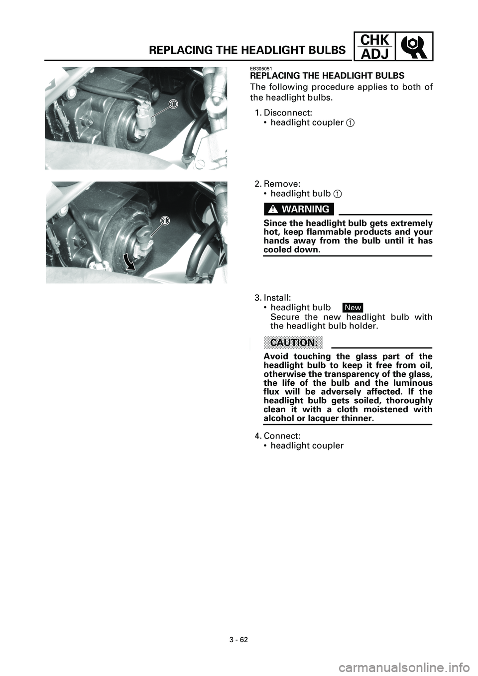
1. Disconnect:
• headlight coupler 1
1�
1�
2. Remove:
• headlight bulb 1
WARNINGWARNING
Since the headlight bulb gets extremely
hot, keep flammable products and your
hands away from the bulb until it has
cooled down.
1�
1�
3. Install:
• headlight bulb
Secure the new headlight bulb with
the headlight bulb holder.
ACHTUNG:CAUTION:
Avoid touching the glass part of the
headlight bulb to keep it free from oil,
otherwise the transparency of the glass,
the life of the bulb and the luminous
flux will be adversely affected. If the
headlight bulb gets soiled, thoroughly
clean it with a cloth moistened with
alcohol or lacquer thinner.
4. Connect:
• headlight coupler
New
Page 163 of 381
4 - 31
ENG
VALVES AND VALVE SPRINGS
4. Install:
• valve cotters
1
NOTE:
Install the valve cotters by compressing
the valve spring with the valve spring
compressor
2
and attachment
3
.
5. To secure the valve cotters
1
onto the
valve stem, lightly tap the valve tip with
a soft-face hammer.
ACHTUNG:CAUTION:
Hitting the valve tip with excessive
force could damage the valve.
Valve spring compressor
90890-04019
Attachment
(for the intake valve spring)
9080-04114
(for the exhaust valve spring)
90890-04108
6. Lubricate:
• valve pad
(with the recommended lubricant)
Recommended lubricant
Molybdenum disulfide oil
7. Install:
• valve pad
• valve lifter
NOTE:
• The valve lifter must move smoothly
when rotated with a finger.
• Each valve lifter and valve pad must be
reinstalled in its original position.
Page 253 of 381
7 - 3
CHAS
FRONT WHEEL AND BRAKE DISCS
EB700102
REMOVING THE FRONT WHEEL
1. Stand the motorcycle on a level surface.
WARNINGWARNING
Securely support the motorcycle so that
there is no danger of it falling over.
NOTE:
Place the motorcycle on a suitable stand
so that the front wheel is elevated.
2. Remove:
• left brake caliper
• right brake caliper
NOTE:
Do not squeeze the brake lever when
removing the brake calipers.
3. Elevate:
• front wheel
NOTE:
Place the motorcycle on a suitable stand
so that the front wheel is elevated.
EB700400
CHECKING THE FRONT WHEEL
1. Check:
• wheel axle
Roll the wheel axle on a flat surface.
Bends
®
Replace.
WARNINGWARNING
Do not attempt to straighten a bent
wheel axle.
2. Check:
• tire
• front wheel
Damage/wear
®
Replace.
Refer to “CHECKING THE TIRES” and
“CHECKING THE WHEELS” in chapter 3.
Page 262 of 381
7 - 12
CHAS
REAR WHEEL, BRAKE DISC, AND REAR WHEEL
SPROCKET
EB701100
REMOVING THE REAR WHEEL
1. Stand the motorcycle on a level surface.
WARNINGWARNING
Securely support the motorcycle so that
there is no danger of it falling over.
NOTE:
Place the motorcycle on a suitable stand
so that the rear wheel is elevated.
2. Remove:
• brake caliper
NOTE:
Do not depress the brake pedal when
removing the brake caliper.
3. Remove:
• wheel axle nut
• washer
• wheel axle
• rear wheel
NOTE:
Push the rear wheel forward and
remove the drive chain from the rear
wheel sprocket.
EB701400
CHECKING THE REAR WHEEL
1. Check:
• wheel axle
• rear wheel
• wheel bearings
• oil seals
• brake disc
Refer to “FRONT WHEEL”.
2. Check:
• tire
• rear wheel
Damage/wear ® Replace.
Refer to “CHECKING THE TIRES” and
“CHECKING THE WHEELS” in chapter 3.
Page 276 of 381

7 - 26
CHAS
EB702317
DISASSEMBLING THE FRONT BRAKE
CALIPERS
The following procedure applies to both of
the brake calipers.
NOTE:
Before disassembling either brake cali-
per, drain the brake fluid from the entire
brake system.
1. Remove:
• union bolt 1
• copper washers 2
• brake hose
NOTE:
Put the end of the brake hose into a con-
tainer and pump out the brake fluid
carefully.
2. Remove:
• brake caliper pistons 1
• brake caliper piston seals 2
t t t t t t t t t t t t t t t t t t t t t t t t t t t
a. Secure the right side brake caliper
pistons with a piece of wood a.
b. Blow compressed air into the brake
hose joint opening b to force out the
left side pistons from the brake cali-
per.
WARNINGWARNING
• Never try to pry out the brake caliper
pistons.
• Do not loosen the bolts 3.
c. Remove the brake caliper piston
seals.
d. Repeat the previous steps to force out
the right side pistons from the brake
caliper.
s s s s s s s s s s s s s s s s s s s s s s s s s s s
FRONT AND REAR BRAKES
Page 277 of 381
7 - 27
CHAS
EB702322
DISASSEMBLING THE REAR BRAKE
CALIPER
NOTE:
Before disassembling the brake caliper,
drain the brake fluid from the entire
brake system.
1. Remove:
• union bolt 1
• copper washers 2
• brake hose
NOTE:
Put the end of the brake hose into a con-
tainer and pump out the brake fluid
carefully.
2. Remove:
• brake caliper pistons 1
• brake caliper piston seals 2
t t t t t t t t t t t t t t t t t t t t t t t t t t t
a. Secure the right side brake caliper
piston with a piece of wood a.
b. Blow compressed air into the brake
hose joint opening b to force out the
left side piston from the brake caliper.
WARNINGWARNING
• Never try to pry out the brake caliper
pistons.
• Do not loosen the bolt 3.
c. Remove the brake caliper piston
seals.
d. Repeat the previous steps to force out
the right side piston from the brake
caliper.
s s s s s s s s s s s s s s s s s s s s s s s s s s s
FRONT AND REAR BRAKES
Page 308 of 381

7 - 58
CHAS
EB703100
REMOVING THE FRONT FORK LEGS
The following procedure applies to both of
the front fork legs.
1. Stand the motorcycle on a level surface.
WARNINGWARNING
Securely support the motorcycle so that
there is no danger of it falling over.
NOTE:
Place the motorcycle on a suitable stand
so that the front wheel is elevated.
2. Adjust:
• spring preload
NOTE:
Turn the adjusting bolt 1 in fully so that
it sits lightly. Refer to “ADJUSTING THE
FRONT FORK LEGS” in chapter 3.
1�
1�
3. Loosen:
• upper bracket pinch bolt 1
• cap bolt 2
(with the front fork cap bolt wrench)
• handlebar pinch bolts
• lower bracket pinch bolts
WARNINGWARNING
Before loosening the upper and lower
bracket pinch bolts and handlebar pinch
bolt, support the front fork leg.
4. Remove:
• front fork leg
Front fork cap bolt wrench:
90890-01472
1�
1�
2�
2�
EB703113
DISASSEMBLING THE FRONT FORK LEGS
The following procedure applies to both of
the front fork legs.
1. Remove:
• cap bolt 1
(from the damper rod assembly)
• straight key
• washer
• damper adjusting rod
4
51
2
3
FRONT FORK
Page 319 of 381

7 - 69
CHAS
EB704101
REMOVING THE HANDLEBARS
1. Stand the motorcycle on a level surface.
WARNINGWARNING
Securely support the motorcycle so that
there is no danger of it falling over.
2. Remove:
• handlebar grip
NOTE:
Blow compressed air between the left
handlebar and the handlebar grip, and
gradually push the grip off the handle-
bar.
EB704401
CHECKING THE HANDLEBARS
1. Check:
• left handlebar
• right handlebar
Bends/cracks/damage ® Replace.
WARNINGWARNING
Do not attempt to straighten bent han-
dlebars as this may dangerously
weaken them.
EB704704
INSTALLING THE HANDLEBARS
1. Install:
• brake master cylinder holder 1
ACHTUNG:CAUTION:
• Install the brake master cylinder
holder with the “UP” mark facing up.
• First, tighten the upper bolt, then the
lower bolt.
NOTE:
• Align the mating surfaces of the brake
master cylinder holder with the punch
mark a in the right handlebar.
• There should be 2 mm of clearance
between the right handlebar switch
and the brake master cylinder holder.
UP UP
UP
a
a
1�
1�
T R..13 Nm (1.3 m · kg, 9.4 ft · lb)
HANDLEBARS