Page 1119 of 4592

CL034±01
± CLUTCHTROUBLESHOOTING
CL±1
1780 Author�: Date�:
TROUBLESHOOTING
PROBLEM SYMPTOMS TABLE
Use the table below to help you find the cause of the problem. The numbers indicate the priority of the likely
cause of the problem. Check each part in order. If necessary, replace these parts.
SymptomSuspect AreaSee page
1. Engine mounting (Loosen)±1. Engine mounting (Loosen)
2. Clutch disc (Runout is excessive)
±
CL±17
2. Clutch disc (Runout is excessive)
3. Clutch disc (Oily)
CL±17
CL±17
Clutch grabs/chatters
3. Clutch disc (Oily)
4. Clutch disc (Worn out)
CL±17
CL±17Clutch grabs/chatters4. Clutch disc (Worn out)
5. Clutch disc torsion rubber (Damaged)
CL±17
CL±175. Clutch disc torsion rubber (Damaged)
6. Clutch disc (Glazed)
CL 17
CL±176. Clutch disc (Glazed)
7. Diaphragm spring (Out of tip alignment)
CL 17
CL±19
1. Clutch line (Air in line)±
Clutch pedal spongy
1. Clutch line (Air in line)
2. Master cylinder cup (Damaged)
±
CL±4
Clutch edal s ongy2. Master cylinder cu (Damaged)
3. Release cylinder cup (Damaged)
CL 4
CL±9
1 Release bearing (Worn dirty or damaged)CL 19Clutch noisy1. Release bearing (Worn, dirty, or damaged)
2Cl hdi i bb (D d)
CL±19
CL 17Clutch noisy2. Clutch disc torsion rubber (Damaged)CL±17
1. Clutch pedal (Freeplay out of adjustment)CL±21. Clutch edal (Free lay out of adjustment)
2. Clutch disc (Oily)
CL±2
CL±17
Cl t h li
2. Clutch disc (Oily)
3. Clutch disc (Worn out)
CL±17
CL±17Clutch slips3. Clutch disc (Worn out)
4. Diaphragm spring (Damaged)
CL 17
CL±174. Dia hragm s ring (Damaged)
5. Pressure plate (Distortion)
CL 17
CL±175. Pressure late (Distortion)
6. Flywheel (Distortion)
CL 17
±
1 Clutchpedal (Freeplay out of adjustment)CL±21. Clutch pedal (Freeplay out of adjustment)
2 Clutch line (Air in line)CL±2
2. Clutch line (Air in line)
3 Master cylinder cup(Damaged)
±
CL 43. Master cylinder cup (Damaged)
4 Release cylinder cup(Damaged)
CL±4
CL 94. Release cylinder cup (Damaged)
5 Clutch disc (out of true)
CL±9
CL 175. Clutch disc (out of true)
6 Cl tch disc (R no t is e cessi e)
CL±17
CL 17
Cl t h d t di
6. Clutch disc (Runout is excessive)
7 Cl t h di (Li i b k )
CL±17
CL 17Clutch does not disengage7. Clutch disc (Lining broken)
8 Cl t h di (Di t b d)
CL±17
CL 178. Clutch disc (Dirty or burned)
Cl h di (Oil )
CL±17
CL9. Clutch disc (Oily)CL±17
10. Clutch disc (Lack of spline grease)CL±19
11. Diaphragm spring (Damaged)CL±17gg(g)
12. Diaphragm spring (Out of tip alignment)CL±19gg( g)
13. Pressure plate (Distortion)CL±17
Page 1135 of 4592
CL03J±01
Q10017
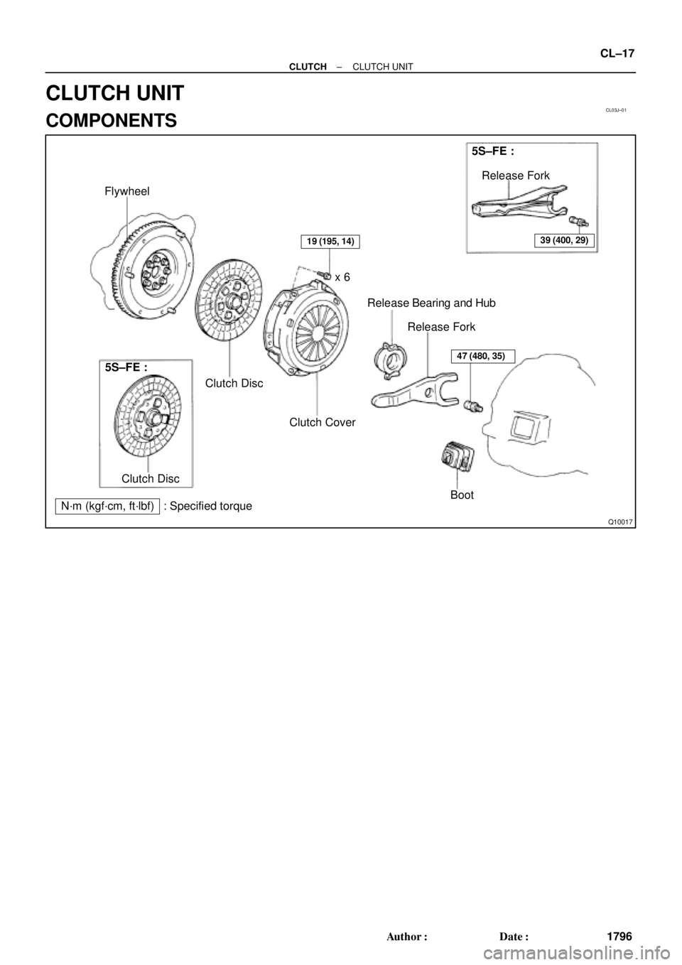
Flywheel
Clutch Disc
19 (195, 14)
47 (480, 35)
Clutch Coverx 6
Release Bearing and Hub
Release Fork5S±FE :
Release Fork
39 (400, 29)
5S±FE :
Clutch Disc
N´m (kgf´cm, ft´lbf) : Specified torqueBoot
± CLUTCHCLUTCH UNIT
CL±17
1796 Author�: Date�:
CLUTCH UNIT
COMPONENTS
Page 1136 of 4592
CL03K±01
Q10161Matchmarks
Z19000
1MZ±FE:
5S±FE: CL±18
± CLUTCHCLUTCH UNIT
1797 Author�: Date�:
REMOVAL
1. REMOVE TRANSAXLE FROM ENGINE
(See page E153 MX±4, S51 MX±4)
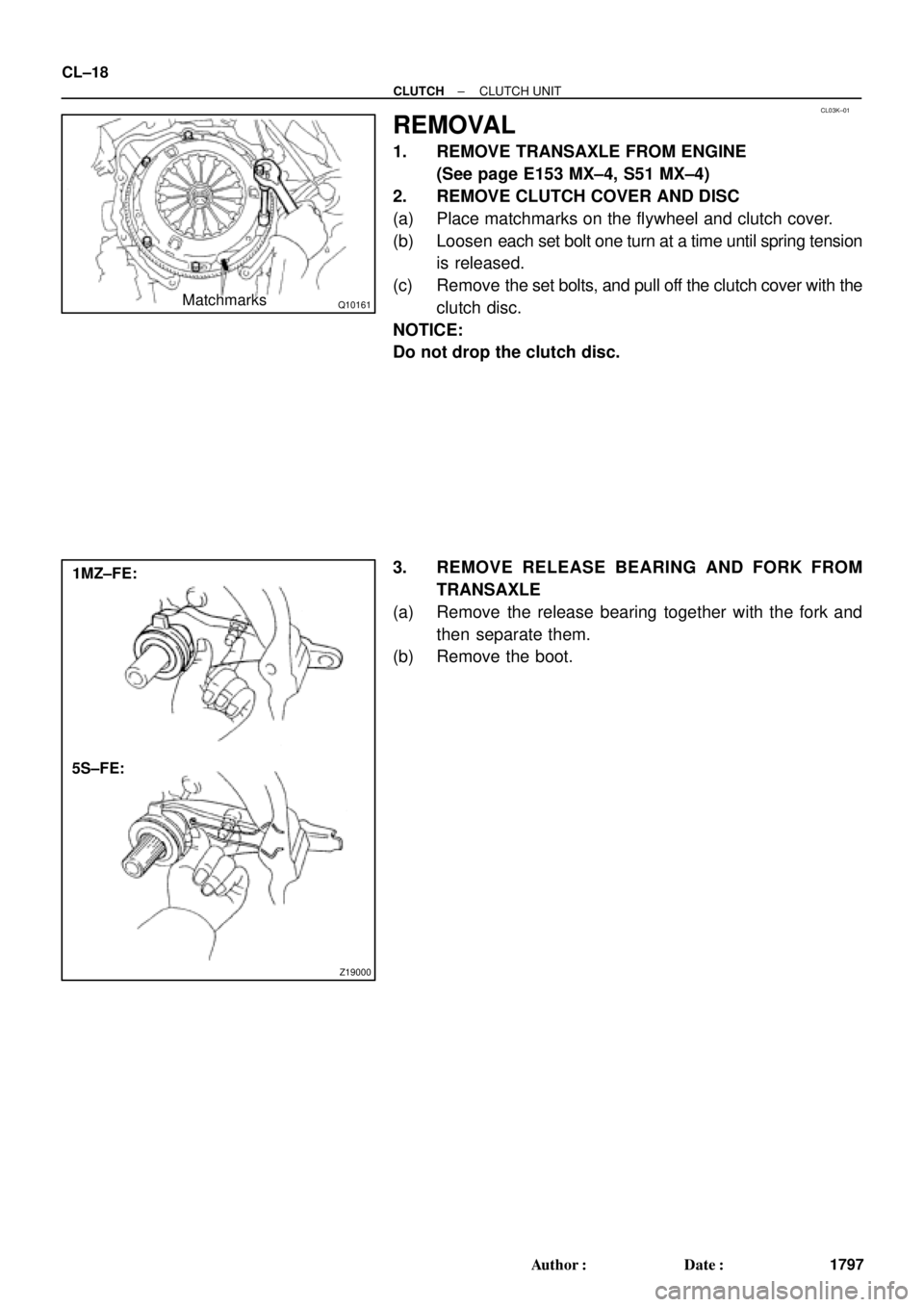
2. REMOVE CLUTCH COVER AND DISC
(a) Place matchmarks on the flywheel and clutch cover.
(b) Loosen each set bolt one turn at a time until spring tension
is released.
(c) Remove the set bolts, and pull off the clutch cover with the
clutch disc.
NOTICE:
Do not drop the clutch disc.
3. REMOVE RELEASE BEARING AND FORK FROM
TRANSAXLE
(a) Remove the release bearing together with the fork and
then separate them.
(b) Remove the boot.
Page 1137 of 4592
CL03L±01
Q10090
1MZ±FE:
5S±FE:
CL0373
CL0372
Z09915
AB
± CLUTCHCLUTCH UNIT
CL±19
1798 Author�: Date�:
INSPECTION
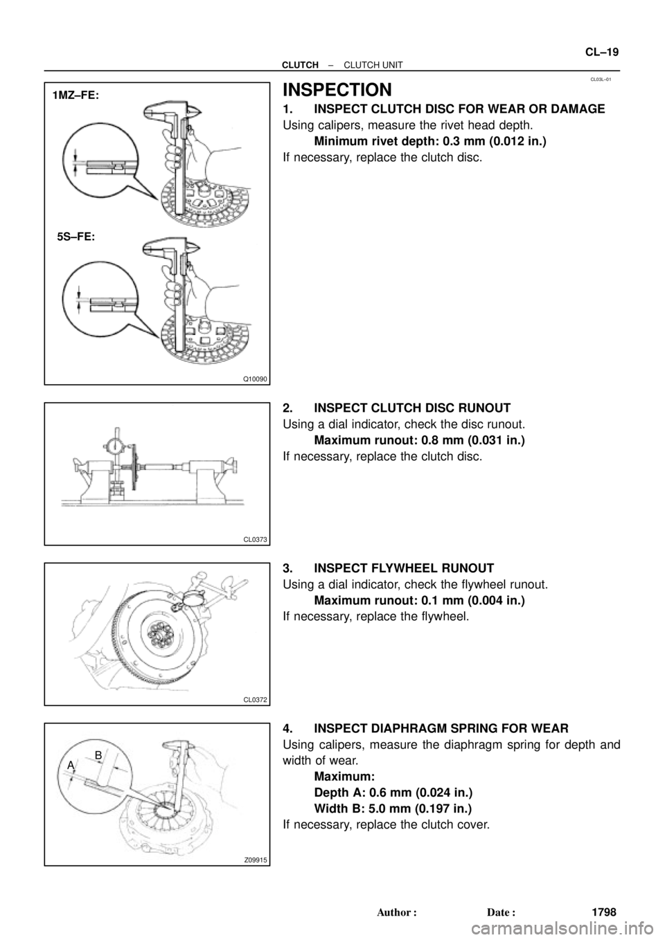
1. INSPECT CLUTCH DISC FOR WEAR OR DAMAGE
Using calipers, measure the rivet head depth.
Minimum rivet depth: 0.3 mm (0.012 in.)
If necessary, replace the clutch disc.
2. INSPECT CLUTCH DISC RUNOUT
Using a dial indicator, check the disc runout.
Maximum runout: 0.8 mm (0.031 in.)
If necessary, replace the clutch disc.
3. INSPECT FLYWHEEL RUNOUT
Using a dial indicator, check the flywheel runout.
Maximum runout: 0.1 mm (0.004 in.)
If necessary, replace the flywheel.
4. INSPECT DIAPHRAGM SPRING FOR WEAR
Using calipers, measure the diaphragm spring for depth and
width of wear.
Maximum:
Depth A: 0.6 mm (0.024 in.)
Width B: 5.0 mm (0.197 in.)
If necessary, replace the clutch cover.
Page 1139 of 4592
CL03M±02
Q10089
1MZ±FE:
5S±FE:SST
Flywheel
Side
SST
Q10084
SST
1
Matchmarks
4
2
6
35
Q10072
SST
± CLUTCHCLUTCH UNIT
CL±21
1800 Author�: Date�:
INSTALLATION
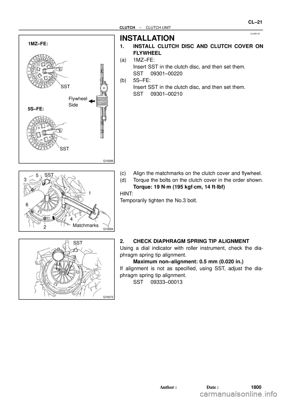
1. INSTALL CLUTCH DISC AND CLUTCH COVER ON
FLYWHEEL
(a) 1MZ±FE:
Insert SST in the clutch disc, and then set them.
SST 09301±00220
(b) 5S±FE:
Insert SST in the clutch disc, and then set them.
SST 09301±00210
(c) Align the matchmarks on the clutch cover and flywheel.
(d) Torque the bolts on the clutch cover in the order shown.
Torque: 19 N´m (195 kgf´cm, 14 ft´lbf)
HINT:
Temporarily tighten the No.3 bolt.
2. CHECK DIAPHRAGM SPRING TIP ALIGNMENT
Using a dial indicator with roller instrument, check the dia-
phragm spring tip alignment.
Maximum non±alignment: 0.5 mm (0.020 in.)
If alignment is not as specified, using SST, adjust the dia-
phragm spring tip alignment.
SST 09333±00013
Page 2618 of 4592
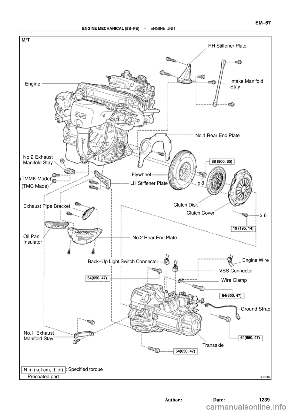
S05316
M/T
Engine
No.2 Exhaust
Manifold Stay
(TMMK Made)
(TMC Made)
Exhaust Pipe Bracket
Oil Pan
Insulator
No.1 Exhaust
Manifold Stay
Back±Up Light Switch ConnectorNo.2 Rear End Plate Flywheel
LH Stiffener Plate
Clutch Disk
Clutch Cover
Engine Wire
VSS Connector
Wire Clamp
Ground Strap
Transaxle No.1 Rear End PlateIntake Manifold
Stay RH Stiffener Plate
N´m (kgf´cm, ft´lbf)
� Precoated partx 8
88 (900, 65)
19 (195, 14)
64(650, 47)
64(650, 47)
64(650, 47)64(650, 47)
�
: Specified torquex 6
± ENGINE MECHANICAL (5S±FE)ENGINE UNIT
EM±67
1239 Author�: Date�:
Page 2625 of 4592
S05531
Wire
Bracket
Ground
Strap
S05314
M/T EM±74
± ENGINE MECHANICAL (5S±FE)ENGINE UNIT
1246 Author�: Date�:
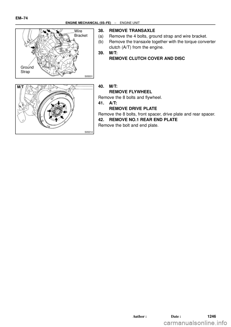
38. REMOVE TRANSAXLE
(a) Remove the 4 bolts, ground strap and wire bracket.
(b) Remove the transaxle together with the torque converter
clutch (A/T) from the engine.
39. M/T:
REMOVE CLUTCH COVER AND DISC
40. M/T:
REMOVE FLYWHEEL
Remove the 8 bolts and flywheel.
41. A/T:
REMOVE DRIVE PLATE
Remove the 8 bolts, front spacer, drive plate and rear spacer.
42. REMOVE NO.1 REAR END PLATE
Remove the bolt and end plate.
Page 2626 of 4592
EM08G±04
EM7333
Z18989
M/T
1
3
5
8
2 4 67
S05531
Wire
Bracket
Ground
Strap
± ENGINE MECHANICAL (5S±FE)ENGINE UNIT
EM±75
1247 Author�: Date�:
INSTALLATION
1. INSTALL NO.1 REAR END PLATE
Install the end plate with the bolt.
Torque: 9.3 N´m (95 kgf´cm, 82 in.´lbf)
2. M/T:
INSTALL FLYWHEEL
(a) Apply adhesive to 2 or 3 threads of the bolt end.
Adhesive:
Part No. 08833±00070, THREE BOND 1324 or equiva-
lent
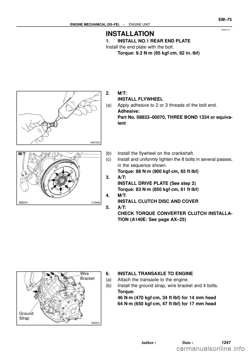
(b) Install the flywheel on the crankshaft.
(c) Install and uniformly tighten the 8 bolts in several passes,
in the sequence shown.
Torque: 88 N´m (900 kgf´cm, 65 ft´lbf)
3. A/T:
INSTALL DRIVE PLATE (See step 2)
Torque: 83 N´m (850 kgf´cm, 61 ft´lbf)
4. M/T:
INSTALL CLUTCH DISC AND COVER
5. A/T:
CHECK TORQUE CONVERTER CLUTCH INSTALLA-
TION (A140E: See page AX±25)
6. INSTALL TRANSAXLE TO ENGINE
(a) Attach the transaxle to the engine.
(b) Install the ground strap, wire bracket and 4 bolts.
Torque:
46 N´m (470 kgf´cm, 34 ft´lbf) for 14 mm head
64 N´m (650 kgf´cm, 47 ft´lbf) for 17 mm head