Page 22 of 349

B07465
New
Previous
– INTRODUCTIONFOR ALL OF VEHICLES
IN–17
5. FOR VEHICLES EQUIPPED WITH POWER WINDOW CONTROL SYSTEM
When the battery is disconnected or the power to the window regulator motor is cut, the power window con-
trol system does not operate. It is necessary to initialize the system in the following procedures. Otherwise
window cannot be operated normally.
(1) Close window to the highest position.
(2) Keep holding the switch for 5 seconds.
(3) Check that automatic operation works. If not, repeat the above procedures.
6. FOR VEHICLES EQUIPPED WITH SLIDING ROOF SYSTEM
Sliding roof stop position might be required to be initialized when battery failures (such as battery disconnec-
tion, connector disconnection and the voltage drop) are detected while the system is in operation. This also
occurs when rotating the motor with the battery disconnected. Sliding roof initialization can be done by the
following procedures.
(1) Operate the roof up to the maximum tilt position.
(2) Release the switch, and push it again in the same direction. (After 10 seconds have elapsed,
initialization begins.)
(3) The roof starts automatic operation if holding the switch, completes full one cycle (tilt down, slide
open, slide close and tilt up) of travel. Do not release the switch until the roof stops.
(4) Check that the roof stops at the correct position.
7. FOR VEHICLES EQUIPPED WITH BRAKE PIPE FIT-
TING OF NEW STANDARD
A flare shape of a new standard is used for the brake pipe fitting
from this changed models.
NOTICE:
�When ordering or replacing the parts, please be sure
to check and use the fitting of the same flare type.
�Do not over–tighten them more than the standard
torque.
Torque: 15 N·m (155 kgf·cm, 11 ft·lbf)
Page 238 of 349
RS0IR–01
H11612
Roof Headlining
Front Pillar GarnishCenter Pillar Upper Garnish
Center Pillar Lower Garnish Front Seat Outer Belt Assist Grip
Front Door Operating Trim
Front Door Scuff Plate
Rear Door Scuff Plate Rear Door Operating Trim
Map Light Sun Visor
Pillar Garnish Cover
H11611
Sedan Model Liftback Model Wagon Model
Roof Side
Inner Garnish
Side Seatback
Rear Seat CushionDeck Trim
Side Board
Rear Floor
Carpet Deck Side Trim
Cover and Panel
Tonneau
Cover
Rear Floor
Finish Plate Rear Seat
Outer Belt
Roof Side
Inner Garnish
Side Seatback
Roof Side
Inner Garnish
Rear Seatback
Assembly
Rear Side
Seatback
Room
Partition
Net
N·m (kgf·cm, ft·lbf): Specified torque
42 (430, 31)
21 (214, 15)
21 (214, 15)
21 (214, 15)
RS–20
– SUPPLEMENTAL RESTRAINT SYSTEMCURTAIN SHIELD AIRBAG ASSEMBLY
CURTAIN SHIELD AIRBAG ASSEMBLY
COMPONENTS
Page 241 of 349

(2)(3)(4)(5)
H11614
Clear Plastic Bag
– SUPPLEMENTAL RESTRAINT SYSTEMCURTAIN SHIELD AIRBAG ASSEMBLY
RS–23
REMOVAL
NOTICE:
�If the wiring")
RS0IS–01
H11626
2 Clips
Pillar Garnish
Cover
H11613
(1)
(2)(3)(4)(5)
H11614
Clear Plastic Bag
– SUPPLEMENTAL RESTRAINT SYSTEMCURTAIN SHIELD AIRBAG ASSEMBLY
RS–23
REMOVAL
NOTICE:
�If the wiring connector of the SRS is disconnected
and the ignition switch is at ON or ACC position, DTCs
will be recorded.
�Never use the airbag parts from another vehicle.
When replacing parts, replace them with new parts.
1. REMOVE FRONT PILLAR GARNISH
(a) Using a screw driver, raise the pillar garnish cover.
(b) Remove the bolt, pillar garnish cover, and front pillar gar-
nish.
2. REMOVE ROOF HEADLINING
�Sedan model (See page BO–23)
�Liftback model (See page BO–28)
�Wagon model (See page BO–33)
3. REMOVE CURTAIN SHIELD AIRBAG
(IN CASE WITHOUT REMOVING INFLATER)
(a) In the order shown in the illustration, remove the bolts and
grommets, then remove the deployment section of the
curtain shield airbag.
(b) Put the removed airbag in the clear plastic bag and put it
on the instrument panel.
NOTICE:
Clear plastic bag is not reuse.
CAUTION:
Never diassemble the curtain shield airbag.
Page 249 of 349

RS0IV–01
– SUPPLEMENTAL RESTRAINT SYSTEMCURTAIN SHIELD AIRBAG ASSEMBLY
RS–31
REPLACEMENT
REPLACEMENT REQUIREMENTS
In the following cases, replace the side airbag assembly.
CaseReplacing part
If the curtain shield airbag has been deployed.Curtain shield airbag assembly
If the curtain shield airbag has been found to be faulty in troubleshooting.Curtain shield airbag assembly
If the curtain shield airbag assembly has been found to be faulty during
checking items.
(See page RS–11)
Curtain shield airbag assembly
If the front pillar garnish and roof headlining has been found to be faulty dur-
ing checking items.
(See page RS–11)Front pillar garnish
Roof headlining
If the instrument panel reinforcement has been found to be faulty during
checking items.
(See page RS–11)
Instrument panel reinforcement
If the curtain shield airbag assembly has been dropped.Curtain shield airbag assembly
CAUTION:
For removal and installation of the side airbag assembly, see page RS–23 and RS–32. Be sure to fol-
low the correct procedure.
Page 250 of 349
(7)
(4)
(6)
(1)(2)(3)
H11613
(1)(2)(3)(4)
(5)
RS–32
– SUPPLEMENTAL RESTRAINT SYSTEMCURTAIN SHIELD AIRBAG ASSEMBLY
INSTALLATION
NOTICE:
�Never use airbag parts from another ve")
RS0IW–01
H11615
(5)(7)
(4)
(6)
(1)(2)(3)
H11613
(1)(2)(3)(4)
(5)
RS–32
– SUPPLEMENTAL RESTRAINT SYSTEMCURTAIN SHIELD AIRBAG ASSEMBLY
INSTALLATION
NOTICE:
�Never use airbag parts from another vehicle. When
replacing parts, replace them with new parts.
�Make sure that the curtain shield airbag assembly is
installed with the specified torque.
�If the curtain shield airbag assembly has been
dropped, or there are cracks, dents or other defects
in the case or connector, replace the curtain shield
airbag assembly with a new one.
�When installing the curtain shield airbag assembly,
take care it is not pinched between other parts.
1. INSTALL CURTAIN SHIELD AIRBAG ASSEMBLY
(a) Connect the connector of the curtain shield airbag sub
wire harness then lock it.
(b) In order shown in the illustration, install the curtain shield
airbag with the bolts and grommets.
Torque:
Nuts: 9.8 N·m (100 kgf·cm, 87 in.·lbf)
Bolts: 5 N·m (51 kgf·cm, 44 in.·lbf)
CAUTION:
Pay attention for not causing twisting.
(c) Install the instrument panel assembly. (See page
BO–19)
2. INSTALL CURTAIN SHIELD AIRBAG
(IN CASE WITHOUT INSTALLING INFLATER)
In order shown in the illustration, install the deployment section
of the curtain shield airbag with the bolts and grommet.
Torque: 5 N·m (51 kgf·cm, 44 in.·lbf)
CAUTION:
Pay attention for not causing twisting.
3. INSTALL ROOF HEADLINING
�Sedan model (See page BO–25)
�Liftback model (See page BO–30)
�Wagon model (See page BO–36)
Page 270 of 349
BODY
CLIP BO–1. . . . . . . . . . . . . . . . . . . . . . . . . . . . . . . . . . . .
WINDSHIELD BO–3. . . . . . . . . . . . . . . . . . . . . . . . . . .
SLIDING ROOF BO–11. . . . . . . . . . . . . . . . . . . . . . . . . .
INSTRUMENT PANEL BO–13. . . . . . . . . . . . . . . . . . . .
ROOF HEADLINING (Sedan) BO–22. . . . . . . . . . . . . .
ROOF HEADLINING (Liftback) BO–27. . . . . . . . . . . . .
ROOF HEADLINING (Wagon) BO–32. . . . . . . . . . . . .
REFER TO AVENSIS/CORONA REPAIR MANUAL FOR
CHASSIS AND BODY (Pub. No. RM599E)
NOTE: The above pages contain only the points which differ
from the above listed manual.
Page 274 of 349
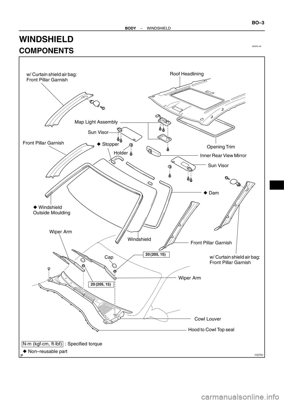
BO0IO–04
I12751
Roof Headlining
Sun Visor Opening Trim
Holder Front Pillar Garnish
� Windshield
Outside Moulding
Front Pillar Garnish Windshield Wiper Arm
N·m (kgf·cm, ft·lbf) : Specified torque
� Non–reusable partWiper Arm
Sun Visor
20 (205, 15)
20 (205, 15)
� Dam Inner Rear View Mirror
Cowl Louver Map Light Assembly
Cap
Hood to Cowl Top seal � Stopper
w/ Curtain shield air bag:
Front Pillar Garnish
w/ Curtain shield air bag:
Front Pillar Garnish
– BODYWINDSHIELD
BO–3
WINDSHIELD
COMPONENTS
Page 280 of 349
 Use a scraper to remove any excessive or protruding
adhesive.
(d) Hold the windshield glass in pl")
BO3986
BO3671AdhesiveAdhesive
H03503
H11626
Pillar Garnish
Cover
2 Clips
– BODYWINDSHIELD
BO–9
(c) Use a scraper to remove any excessive or protruding
adhesive.
(d) Hold the windshield glass in place securely with protec-
tive tape or equivalent until the adhesive hardenes.
NOTICE:
Take care not to drive the vehicle during the time described
in the table below.
TemperatureMinimum time prior to driving the vehicle
35�C (95�F)1.5 hours
20�C (68�F)5 hours
5�C (41�F)24 hours
11. INSPECT FOR LEAKAGE AND REPAIR
(a) Do a leak test after the hardening time has elapsed.
(b) Seal any leakage with sealant.
Part No. 08833–00030 or equivalent
12. APPLY ADHESIVE AT MOULDING INSTALLATION
AREA
Coat the glass with adhesive at the moulding installation area.
Part No. 08833–00030 or equivalent
13. INSTALL WINDSHIELD MOULDING
Place the moulding onto the body and tap it by hand.
14. INSTALL THESE PARTS:
(a) Install the front part of roof headlining.
(b) Install the inner rear view mirror
(c) w/ Curtain Shield Air Bag:
(1) Remove the protection cover.
(2) Install the 2 bolts.
Torque: 5 N·m (51 kgf·cm, 44 in.·lbf)
(3) Install the front pillar garnish.
(4) Install the pillar garnish cover and bolt.
NOTICE:
Be sure to tighten the bolt.
(5) Fell the pillar garnish cover.
(d) Install the front pillar garnishes.