Page 149 of 349
MANUAL TRANSAXLE ASSEMBLY
(j) Using a torque wrench, measure the preload.
Preload (at starting):
New bearing
0.8 – 1.6 N·m (8 – 16 kgf·cm, 6.9 – 13.9")
Z12593
MX–22
– MANUAL TRANSAXLE (E251)MANUAL TRANSAXLE ASSEMBLY
(j) Using a torque wrench, measure the preload.
Preload (at starting):
New bearing
0.8 – 1.6 N·m (8 – 16 kgf·cm, 6.9 – 13.9 in.·lbf)
Reused bearing
0.5 – 1.0 N·m (5 – 10 kgf·cm, 4.3 – 8.7 in.·lbf)
If the preload is not within the specification, select an appropri-
ate adjusting shim.
The preload will change about 0.4 – 0.5 N·m (4 – 5 kgf·cm, 3.5
– 4.3 in.·lbf) for every 0.05 mm change in adjusting shim thick-
ness.
MarkThickness mm (in.)MarkThickness mm (in.)
01.30 (0.0512)D1.95 (0.0768)
11.35 (0.0531)E2.00 (0.0787)
21.40 (0.0551)F2.05 (0.0807)
31.45 (0.0571)G2.10 (0.0827)
41.50 (0.0591)H2.15 (0.0846)
51.55 (0.0610)J2.20 (0.0866)
61.60 (0.0630)K2.25 (0.0886)
71.65 (0.0650)L2.30 (0.0906)
81.70 (0.0669)M2.35 (0.0925)
91.75 (0.0689)N2.40 (0.0945)
A1.80 (0.0709)P2.45 (0.0965)
B1.85 (0.0728)Q2.50 (0.0984)
C1.90 (0.0748)––
(k) Remove the lock nut.
(l) Remove these parts. Removal is in the reverse order of
installation.
�Rear bearing retainer
�Shim
�Transmission case
�Output shaft assembly
�Output shaft rear bearing outer race
Page 153 of 349
INPUT SHAFT
INSPECTION
1. INSPECT 3RD GEAR SYNCHRONIZER RING
(a) Check for wear or damage.
(b) Check the braking effect of the")
MX02A–03
MT0780
MT0786
WM0064
WM0065
MX–26
– MANUAL TRANSAXLE (E251)INPUT SHAFT
INSPECTION
1. INSPECT 3RD GEAR SYNCHRONIZER RING
(a) Check for wear or damage.
(b) Check the braking effect of the synchronizer ring. Turn the
synchronizer ring in one direction while pushing it to the
gear cone. Check that the ring locks.
If it does not lock, replace the synchronizer ring.
(c) Using a feeler gauge, measure the clearance between
the synchronizer ring back and gear spline end.
Minimum clearance: 0.7 mm (0.028 in.)
If the clearance is less than the minimum, replace the synchro-
nizer ring.
2. INSPECT 4TH GEAR SYNCHRONIZER RING
(a) Check for wear or damage.
(b) Check the braking effect of the synchronizer ring. Turn the
synchronizer ring in one direction while pushing it to the
gear cone. Check that the ring locks.
If the braking effect is insufficient, apply a small amount of the
fine lapping compound between the synchronizer ring and gear
cone. Lightly rub the synchronizer ring and gear cone together.
NOTICE:
Ensure the fine lapping compound is completely washed
off after rubbing.
(c) Check again the braking effect of the synchronizer ring.
(d) Using a feeler gauge, measure the clearance between
the synchronizer ring back and spline end.
Minimum clearance: 0.8 mm (0.031 in.)
If the clearance is less than the minimum, replace the synchro-
nizer ring, and apply a small amount of the fine lapping com-
pound on gear cone.
NOTICE:
Ensure the fine lapping compound is completely washed
off after rubbing.
Page 160 of 349
OUTPUT SHAFT
MX–33
INSPECTION
1. INSPECT 1ST GEAR SYNCHRONIZER RING
(a) Check for wear or damage.
(b) Check the braking effect of th")
WM0064
MX02E–03
WM0065
MT0780
MT0787
– MANUAL TRANSAXLE (E251)OUTPUT SHAFT
MX–33
INSPECTION
1. INSPECT 1ST GEAR SYNCHRONIZER RING
(a) Check for wear or damage.
(b) Check the braking effect of the synchronizer ring. Turn the
synchronizer ring in one direction while pushing it to the
gear cone. Check that the ring locks.
If the braking effect is insufficient, apply a small amount of the
fine lapping compound between the synchronizer ring and gear
cone. Lightly rub the synchronizer ring and gear cone together.
NOTICE:
Ensure the fine lapping compound is completely washed
off after rubbing.
(c) Check again the braking effect of the synchronizer ring.
(d) Using a feeler gauge, measure the clearance between
the synchronizer ring back and gear spline end.
Minimum clearance: 0.8 mm (0.031 in.)
If the clearance is less than the minimum, replace the synchro-
nizer ring, and apply a small amount of the fine lapping com-
pound on gear cone.
NOTICE:
Ensure the fine lapping compound is completely washed
off after rubbing.
2. INSPECT 2ND GEAR SYNCHRONIZER RING
(a) Check for wear or damage.
(b) Check the braking effect of the synchronizer ring.
Turn the synchronizer ring in one direction while pushing
it to the gear cone. Check that the ring locks.
If it does not lock, replace the synchronizer ring.
(c) Using a feeler gauge, measure the clearance between
the synchronizer ring back and gear spline end.
Minimum clearance: 0.7 mm (0.028 in.)
If the clearance is less than the minimum, replace the synchro-
nizer ring.
Page 167 of 349
MX02I–03
Q06217
Shift Interlock Plate
Transmission Oil Baffle Shift Interlock Plate
No.1 Compression SpringControl Shaft Cover
Oil Seal
Snap Ring
No.1 Select Spring Seat
Slotted Spring Pin
No.1 Shift Inner Lever
Shift and Select Lever Shaft Snap Ring
Non–reusable partNo.2 Select Spring SeatNo.2 Compression SpringNo.2 Shift Inner LeverSlotted Spring Pin
Apply MP grease �
Dust Boot
� MX–40
– MANUAL TRANSAXLE (E251)SHIFT AND SELECT LEVER SHAFT
SHIFT AND SELECT LEVER SHAFT
COMPONENTS
Page 174 of 349
DIFFERENTIAL CASE
MX–47
12. ADJUST DIFFERENTIAL CASE SIDE BEARING PRE-
LOAD
(a) Install a new lock nut to the output shaft.
(b) Turn the output shaft right a")
Q00036
Z00309
– MANUAL TRANSAXLE (E251)DIFFERENTIAL CASE
MX–47
12. ADJUST DIFFERENTIAL CASE SIDE BEARING PRE-
LOAD
(a) Install a new lock nut to the output shaft.
(b) Turn the output shaft right and left 2 or 3 times to allow the
bearings to settle.
(c) Using a torque wrench, measure the preload.
Preload (at starting):
New bearing (Output shaft preload plus)
0.2 – 0.3 N·m (1.8 – 3.5 kgf·cm, 1.6 – 3.0 in.·lbf)
Reused bearing (Output shaft preload plus)
0.1 – 0.2 N·m (1.1 – 2.2 kgf·cm, 1.0 – 1.9 in.·lbf)
If the preload is not within the specification, select an appropri-
ate adjusting shim.
HINT:
The total preload will change by about 0.1 – 0.2 N·m (1 – 2
kgf·cm, 0.9 – 1.7 in.·lbf) with each 0.05 mm change in adjusting
shim thickness.
MarkThickness mm (in.)MarkThickness mm (in.)
02.00 (0.0787)92.45 (0.0965)
12.05 (0.0807)A2.50 (0.0984)
22.10 (0.0827)B2.55 (0.1004)
32.15 (0.0846)C2.60 (0.1024)
42.20 (0.0866)D2.65 (0.1043)
52.25 (0.0886)E2.70 (0.1063)
62.30 (0.0906)F2.75 (0.1083)
72.35 (0.0925)G2.80 (0.1102)
82.40 (0.0945)H2.85 (0.1122)
13. REMOVE REAR BEARING RETAINER
Using a torx wrench (T45), remove the 7 torx screws and rear
bearing retainer.
14. REMOVE SHIM
15. REMOVE TRANSMISSION CASE
(a) Remove the 17 bolts.
(b) Using a plastic hammer, tap the transmission case.
16. REMOVE OUTPUT SHAFT ASSEMBLY
17. REMOVE DIFFERENTIAL CASE ASSEMBLY
Page 178 of 349
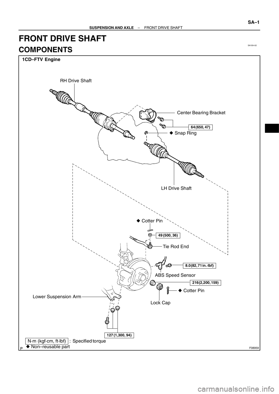
SA109–02
F08959
1CD–FTV Engine
Tie Rod End
ABS Speed Sensor � Cotter Pin
Lock Cap
� Non–reusable part
N·m (kgf·cm, ft·lbf) : Specified torqueLH Drive Shaft� Snap Ring
� Cotter Pin
Center Bearing Bracket
64 (650, 47)
49 (500, 36)
8.0 (82, 71 in.·lbf)
216 (2,200, 159)
RH Drive Shaft
127 (1,300, 94)
Lower Suspension Arm
– SUSPENSION AND AXLEFRONT DRIVE SHAFT
SA–1
FRONT DRIVE SHAFT
COMPONENTS
Page 180 of 349

SA10A–02
FA1535
SST
F02688
F02721
F02724
– SUSPENSION AND AXLEFRONT DRIVE SHAFT
SA–3
REMOVAL
NOTICE:
�The hub bearing could be damaged if it is subjected
to the vehicle weight, such as when moving the ve-
hicle with the drive shaft removed.
Therefore, if it is absolutely necessary to place the ve-
hicle weight on the hub bearing, first support it with
the SST.
SST 09608–16042 (09608–02021, 09608–02041)
�w/ ABS:
After disconnecting the drive shaft from the axle hub,
work carefully so as not to damage the ABS speed
sensor rotor serration on the drive shaft.
1. REMOVE FRONT WHEEL
2. DRAIN OUT GEAR OIL
3. w/ ABS:
REMOVE BOLT AND ABS SPEED SENSOR
4. REMOVE DRIVE SHAFT LOCK NUT
(a) Remove the cotter pin and lock cap.
(b) While applying the brakes, remove the nut.
5. DISCONNECT TIE ROD END FROM STEERING
KNUCKLE (See Pub. No. RM599E on page SA–11)
6. DISCONNECT LOWER BALL JOINT FROM LOWER
SUSPENSION ARM (See Pub. No. RM599E on page
SA–11)
7. DISCONNECT DRIVE SHAFT FROM AXLE HUB
(a) Using a plastic hammer, disconnect the drive shaft from
the axle hub.
NOTICE:
Cover the drive shaft boot and ABS speed sensor rotor with
cloth to protect it from being damaged.
(b) Push the front axle hub toward the outside of the vehicle
to separate the drive shaft from the axle hub.
8. REMOVE DRIVE SHAFTS
(a) RH drive shaft:
Remove the 2 bolts and pull out the drive shaft together
with the center bearing bracket.
Page 187 of 349
 Install a new snap ring to the inboard joint shaft.
(b) Coat the gear o")
SA02Z–03
SA–10
– SUSPENSION AND AXLEFRONT DRIVE SHAFT
INSTALLATION
1. LH drive shaft:
INSTALL DRIVE SHAFT TO TRANSAXLE
(a) Install a new snap ring to the inboard joint shaft.
(b) Coat the gear oil to the inboard joint shaft and differential case sliding surface.
(c) Set the snap ring with opening side facing downward.
(d) Using a brass bar and hammer, install the drive shaft.
NOTICE:
Be careful not to damage the dust cover of the drive shaft and oil seal lip of the transaxle.
HINT:
Whether the inboard joint shaft is in contact with the pinion shaft or not can be known from the sound or feel-
ing when driving it in.
(e) Check that there is 2 – 3 mm (0.08 – 0.12 in.) of play in the axial direction.
(f) Check that the drive shaft cannot be removed by hand.
2. RH drive shaft:
INSTALL DRIVE SHAFT TO TRANSAXLE
(a) Coat the gear oil to the inboard joint shaft and differential case sliding surface.
(b) Install the drive shaft with the center bearing bracket.
NOTICE:
Be careful not to damage the dust cover of the drive shaft and oil seal lip of the transaxle.
(c) Install the 2 bolts.
Torque: 64 N·m (650 kgf·cm, 47 ft·lbf)
3. CONNECT DRIVE SHAFT TO AXLE HUB
NOTICE:
Be careful not to damage the boot and ABS speed sensor rotor.
4. CONNECT LOWER SUSPENSION ARM TO LOWER BALL JOINT
Torque: 127 N·m (1,300 kgf·cm, 94 ft·lbf)
5. CONNECT TIE ROD END TO STEERING KNUCKLE
(a) Connect the tie rod end to the steering knuckle.
(b) Install the nut and a new cotter pin.
If the holes for the cotter pin are not aligned, tighten the nut further up to 60�.
Torque: 49 N·m (500 kgf·cm, 36 ft·lbf)
6. INSTALL DRIVE SHAFT LOCK NUT
(a) While applying brakes, install the nut.
Torque: 216 N·m (2,200 kgf·cm, 159 ft·lbf)
(b) Install the lock cap and a new cotter pin.
If the holes for the cotter pin are not aligned, tighten the nut further up to 60�.
7. w/ABS:
INSTALL ABS SPEED SENSOR AND BOLT
Torque: 8.0 N·m (82 kgf·cm, 71 in.·lbf)
8. FILL AND CHECK GEAR OIL (See page MX–4)
9. INSTALL FRONT WHEEL
Torque: 103 N·m (1,050 kgf·cm, 76 ft·lbf)
10. CHECK FRONT WHEEL ALIGNMENT (See Pub. No. RM599E on page SA–4)
11. CHECK ABS SPEED SENSOR SIGNAL (See Pub. No. RM599E on page DI–115)