������F08950
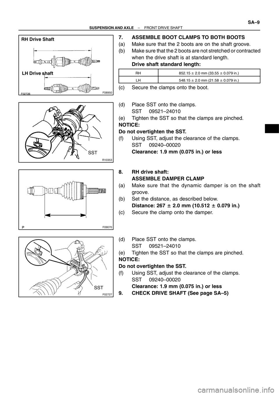
RH Drive Shaft
LH Drive shaft
R10353
SST
F09070
F02727
SST
– SUSPENSION AND AXLEFRONT DRIVE SHAFT
SA–9
7. ASSEMBLE BOOT CLAMPS TO BOTH BOOTS
(a) Make sure that the 2 boots are on the shaft groove.
(b) Make sure that the 2 boots are not stretched or contracted
when the drive shaft is at standard length.
Drive shaft standard length:
RH852.15 � 2.0 mm (33.55 � 0.079 in.)
LH548.15 � 2.0 mm (21.58 � 0.079 in.)
(c) Secure the clamps onto the boot.
(d) Place SST onto the clamps.
SST 09521–24010
(e) Tighten the SST so that the clamps are pinched.
NOTICE:
Do not overtighten the SST.
(f) Using SST, adjust the clearance of the clamps.
SST 09240–00020
Clearance: 1.9 mm (0.075 in.) or less
8. RH drive shaft:
ASSEMBLE DAMPER CLAMP
(a) Make sure that the dynamic damper is on the shaft
groove.
(b) Set the distance, as described below.
Distance: 267 � 2.0 mm (10.512 � 0.079 in.)
(c) Secure the clamp onto the damper.
(d) Place SST onto the clamps.
SST 09521–24010
(e) Tighten the SST so that the clamps are pinched.
NOTICE:
Do not overtighten the SST.
(f) Using SST, adjust the clearance of the clamps.
SST 09240–00020
Clearance: 1.9 mm (0.075 in.) or less
9. CHECK DRIVE SHAFT (See page SA–5)
SA02Z–03
SA–10
– SUSPENSION AND AXLEFRONT DRIVE SHAFT
INSTALLATION
1. LH drive shaft:
INSTALL DRIVE SHAFT TO TRANSAXLE
(a) Install a new snap ring to the inboard joint shaft.
(b) Coat the gear oil to the inboard joint shaft and differential case sliding surface.
(c) Set the snap ring with opening side facing downward.
(d) Using a brass bar and hammer, install the drive shaft.
NOTICE:
Be careful not to damage the dust cover of the drive shaft and oil seal lip of the transaxle.
HINT:
Whether the inboard joint shaft is in contact with the pinion shaft or not can be known from the sound or feel-
ing when driving it in.
(e) Check that there is 2 – 3 mm (0.08 – 0.12 in.) of play in the axial direction.
(f) Check that the drive shaft cannot be removed by hand.
2. RH drive shaft:
INSTALL DRIVE SHAFT TO TRANSAXLE
(a) Coat the gear oil to the inboard joint shaft and differential case sliding surface.
(b) Install the drive shaft with the center bearing bracket.
NOTICE:
Be careful not to damage the dust cover of the drive shaft and oil seal lip of the transaxle.
(c) Install the 2 bolts.
Torque: 64 N·m (650 kgf·cm, 47 ft·lbf)
3. CONNECT DRIVE SHAFT TO AXLE HUB
NOTICE:
Be careful not to damage the boot and ABS speed sensor rotor.
4. CONNECT LOWER SUSPENSION ARM TO LOWER BALL JOINT
Torque: 127 N·m (1,300 kgf·cm, 94 ft·lbf)
5. CONNECT TIE ROD END TO STEERING KNUCKLE
(a) Connect the tie rod end to the steering knuckle.
(b) Install the nut and a new cotter pin.
If the holes for the cotter pin are not aligned, tighten the nut further up to 60�.
Torque: 49 N·m (500 kgf·cm, 36 ft·lbf)
6. INSTALL DRIVE SHAFT LOCK NUT
(a) While applying brakes, install the nut.
Torque: 216 N·m (2,200 kgf·cm, 159 ft·lbf)
(b) Install the lock cap and a new cotter pin.
If the holes for the cotter pin are not aligned, tighten the nut further up to 60�.
7. w/ABS:
INSTALL ABS SPEED SENSOR AND BOLT
Torque: 8.0 N·m (82 kgf·cm, 71 in.·lbf)
8. FILL AND CHECK GEAR OIL (See page MX–4)
9. INSTALL FRONT WHEEL
Torque: 103 N·m (1,050 kgf·cm, 76 ft·lbf)
10. CHECK FRONT WHEEL ALIGNMENT (See Pub. No. RM599E on page SA–4)
11. CHECK ABS SPEED SENSOR SIGNAL (See Pub. No. RM599E on page DI–115)
 Install a new snap ring to the inboard joint shaft.
(b) Coat the gear o")