Page 299 of 656
6A2-12 ENGINE MECHANICAL (H27 ENGINE)
7) Reverse removal procedure to install front propeller shaft if
removed.
When installing propeller shaft, align match mark (1).
Use following specification to torque universal joint flange.
Tightening torque
Universal joint flange bolt (c) :
55 N·m (5.5 kg-m, 40.0 lb-ft)
8) Connect EGR pipe to left (No.1) bank exhaust manifold (1).
9) Install exhaust manifold covers (2).
10) Install oil level gauge guide (3) using new O-ring.
11) Install P/S pump assembly (4) if it was removed. Refer to
“POWER STEERING PUMP” in Section 3B1.
12) Adjust P/S pump drive belt tension, refer to “POWER
STEERING BELT CHECK AND ADJUSTMENT” in Section
3B1.
13) Connect oxygen sensor lead wire couplers.
Be sure to clamp its lead wires.
14) Connect negative (–) cable to battery.
Upon completion of installation, start engine and check that
no exhaust gas leakage exists.
1
4
32
1. HO2S-1 (Green connector)
2. HO2S-2 (Black connector)
Page 300 of 656
ENGINE MECHANICAL (H27 ENGINE) 6A2-13
LH (No.1) Bank 2nd Timing Chain and Chain Tensioner
1. LH bank 2nd timing chain 5. Camshaft sprocket bolt 9. Timing chain tensioner adjuster No. 3 bolt
2. Timing chain tensioner adjuster No.3 6. Timing chain guide No.4 10. Timing chain tensioner adjuster No. 3 nut
3. LH bank intake camshaft sprocket 7. Timing chain guide No.5 11. Timing chain guide No. 4 bolt
4. LH bank exhaust camshaft sprocket 8. Idler sprocket No.2 Tightening Torque
Page 301 of 656
6A2-14 ENGINE MECHANICAL (H27 ENGINE)
Camshaft and Valve Lash Adjuster
1. RH bank 2nd timing chain 6. LH bank intake camshaft 11. Timing chain guide No.5
2. RH bank exhaust camshaft 7. LH bank exhaust camshaft 12. Valve lash adjuster
3. RH bank intake camshaft 8. LH bank intake camshaft holder 13. Camshaft housing bolt
4. RH bank exhaust camshaft holder 9. LH bank exhaust camshaft holder Tightening Torque
5. RH bank intake camshaft holder 10. LH bank camshaft holder Apply engine oil to sliding surface
of each parts.
Page 302 of 656

ENGINE MECHANICAL (H27 ENGINE) 6A2-15
INSPECTION
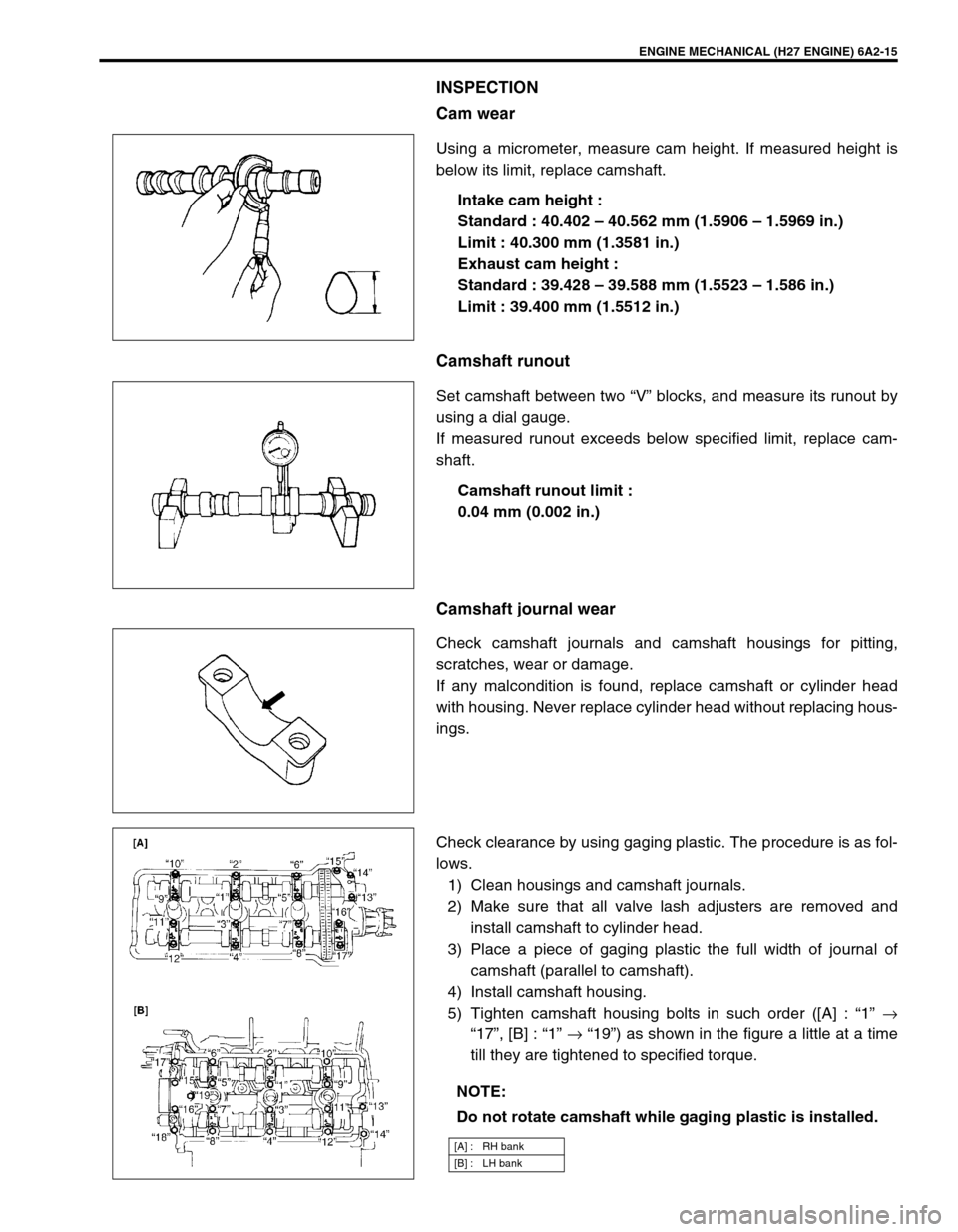
Cam wear
Using a micrometer, measure cam height. If measured height is
below its limit, replace camshaft.
Intake cam height :
Standard : 40.402 – 40.562 mm (1.5906 – 1.5969 in.)
Limit : 40.300 mm (1.3581 in.)
Exhaust cam height :
Standard : 39.428 – 39.588 mm (1.5523 – 1.586 in.)
Limit : 39.400 mm (1.5512 in.)
Camshaft runout
Set camshaft between two “V” blocks, and measure its runout by
using a dial gauge.
If measured runout exceeds below specified limit, replace cam-
shaft.
Camshaft runout limit :
0.04 mm (0.002 in.)
Camshaft journal wear
Check camshaft journals and camshaft housings for pitting,
scratches, wear or damage.
If any malcondition is found, replace camshaft or cylinder head
with housing. Never replace cylinder head without replacing hous-
ings.
Check clearance by using gaging plastic. The procedure is as fol-
lows.
1) Clean housings and camshaft journals.
2) Make sure that all valve lash adjusters are removed and
install camshaft to cylinder head.
3) Place a piece of gaging plastic the full width of journal of
camshaft (parallel to camshaft).
4) Install camshaft housing.
5) Tighten camshaft housing bolts in such order ([A] : “1” →
“17”, [B] : “1” → “19”) as shown in the figure a little at a time
till they are tightened to specified torque.
NOTE:
Do not rotate camshaft while gaging plastic is installed.
[A] : RH bank
[B] : LH bank
Page 304 of 656
ENGINE MECHANICAL (H27 ENGINE) 6A2-17
Valves and Cylinder Heads
1. Cylinder block 6. Exhaust valve 11. Valve stem oil seal 16. Cylinder head bolt
(hex hole bolt)
2. RH bank cylinder head 7. Intake valve 12. Valve spring retainer Tightening Torque
3. LH bank cylinder head 8. Valve spring seat 13. Valve cotter Do not reuse
4. RH bank cylinder head gasket :
Carved lot number on cylinder head
gasket should face up (toward cylinder
head side).9. Outer valve spring :
Be sure to position spring in place with
its bottom end (small-pitch end) facing
the bottom (valve spring seat side).14. Valve guide Apply engine oil to
sliding surface of
each parts.
5. LH bank cylinder head gasket :
Carved lot number on cylinder head
gasket should face up (toward cylinder
head side).10. Inner valve spring :
Be sure to position spring in place with
its bottom end (small-pitch end) facing
the bottom (valve spring seat side).15. Cylinder head bolt
Page 306 of 656

ENGINE MECHANICAL (H27 ENGINE) 6A2-19
5) Install cylinder head to block.
After applying oil to cylinder head bolts, tighten them gradu-
ally as follows.
a) Tighten all bolts to 53 N·m (5.3 kg-m, 38.5 lb-ft) according
to numerical order in the figure.
b) In the same manner as in a), tighten them to 84 N·m (8.4
kg-m, 61.0 lb-ft).
c) Loosen all bolts until tightening torque is reduced to 0 in
reverse order of tightening.
d) In the same manner as in a), tighten them to 53 N·m (5.3
kg-m, 38.5 lb-ft).
e) In the same manner as in a) again, tighten them to speci-
fied torque.
Tightening torque
Cylinder head bolt (a) : 105 N·m (10.5 kg-m, 76.0 lb-ft)
Cylinder head bolt (hex hole bolt) (b) :
11 N·m (1.1 kg-m, 7.5 lb-ft)
6) Install water outlet cap.
7) Check timing mark on crankshaft as shown in the figure.
8) Install valve lash adjuster, camshaft, CMP sensor and RH
bank 2nd timing chain.
Refer to “CAMSHAFT AND VALVE LASH ADJUSTER” and
“RH (NO.2) BANK 2ND TIMING CHAIN AND CHAIN TEN-
SIONER” in this section. For CMP sensor, refer to “CMP
SENSOR” in Section 6F2.
9) Install 1st timing chain.
Refer to “1ST TIMING CHAIN AND CHAIN TENSIONER” in
this section.
10) Install LH bank 2nd timing chain.
Refer to “LH (NO.1) BANK 2ND TIMING CHAIN AND CHAIN
TENSIONER” in this section.
11) Install timing chain cover.
Refer to “TIMING CHAIN COVER” in this section. NOTE:
Don’t forget to install (b) bolts as shown in the figure.
1. Hex hole bolt
2. Crankshaft pulley side
3. Flywheel side
[A] RH bank
[B] LH bank
1. Crank timing pulley key
2. Oil jet
Page 308 of 656
ENGINE MECHANICAL (H27 ENGINE) 6A2-21
Piston, Piston Rings, Connecting Rods and Cylinders
1. Top ring 5. Connecting rod :
Clean bearing installing surface when install.9. Piston pin circlip Tightening Torque
2. 2nd ring 6. Connecting rod bearing cap :
Clean bearing installing surface when install.10. Cylinder block Do not reuse
3. Oil ring 7. Connecting rod bearing :
Clean outer surface when install.11. Bearing cap nut Apply engine oil to sliding
surface of each parts.
4. Piston 8. Piston pin
Page 315 of 656

6A2-28 ENGINE MECHANICAL (H27 ENGINE)
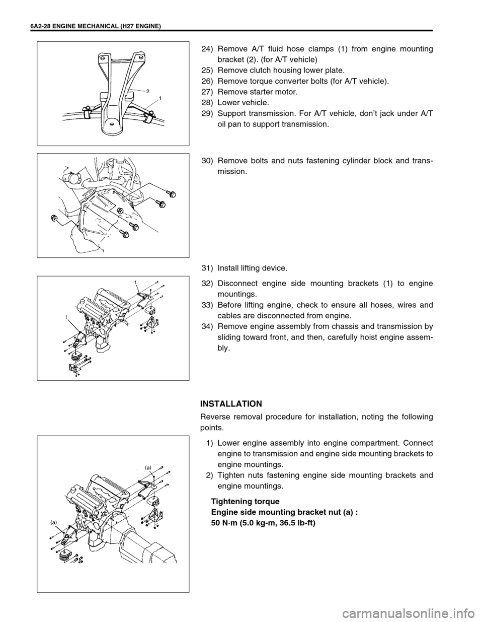
24) Remove A/T fluid hose clamps (1) from engine mounting
bracket (2). (for A/T vehicle)
25) Remove clutch housing lower plate.
26) Remove torque converter bolts (for A/T vehicle).
27) Remove starter motor.
28) Lower vehicle.
29) Support transmission. For A/T vehicle, don’t jack under A/T
oil pan to support transmission.
30) Remove bolts and nuts fastening cylinder block and trans-
mission.
31) Install lifting device.
32) Disconnect engine side mounting brackets (1) to engine
mountings.
33) Before lifting engine, check to ensure all hoses, wires and
cables are disconnected from engine.
34) Remove engine assembly from chassis and transmission by
sliding toward front, and then, carefully hoist engine assem-
bly.
INSTALLATION
Reverse removal procedure for installation, noting the following
points.
1) Lower engine assembly into engine compartment. Connect
engine to transmission and engine side mounting brackets to
engine mountings.
2) Tighten nuts fastening engine side mounting brackets and
engine mountings.
Tightening torque
Engine side mounting bracket nut (a) :
50 N·m (5.0 kg-m, 36.5 lb-ft)