1999 SUZUKI GRAND VITARA torque
[x] Cancel search: torquePage 119 of 656

5C-2 PARKING AND REAR BRAKE
General Description
Drum Brake Assembly
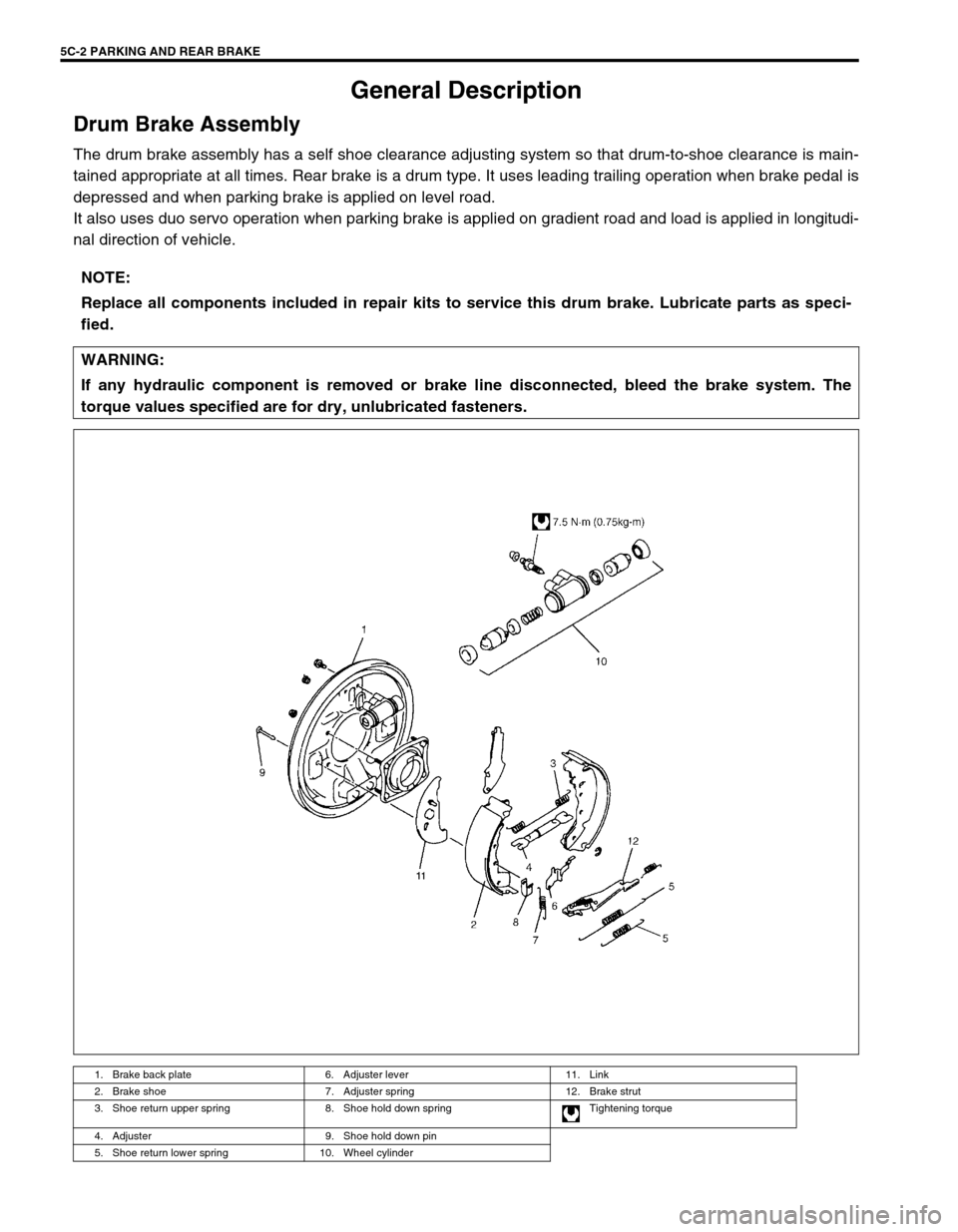
The drum brake assembly has a self shoe clearance adjusting system so that drum-to-shoe clearance is main-
tained appropriate at all times. Rear brake is a drum type. It uses leading trailing operation when brake pedal is
depressed and when parking brake is applied on level road.
It also uses duo servo operation when parking brake is applied on gradient road and load is applied in longitudi-
nal direction of vehicle.
NOTE:
Replace all components included in repair kits to service this drum brake. Lubricate parts as speci-
fied.
WARNING:
If any hydraulic component is removed or brake line disconnected, bleed the brake system. The
torque values specified are for dry, unlubricated fasteners.
1. Brake back plate 6. Adjuster lever 11. Link
2. Brake shoe 7. Adjuster spring 12. Brake strut
3. Shoe return upper spring 8. Shoe hold down spring Tightening torque
4. Adjuster 9. Shoe hold down pin
5. Shoe return lower spring 10. Wheel cylinder
Page 120 of 656

PARKING AND REAR BRAKE 5C-3
On-Vehicle Service
Parking Brake CableBrake Drum
INSPECTION
Brake drum
Inspect drum for cleanliness. Check wear of its braking surface by
measuring its inside diameter.
Whenever brake drums are removed, they should be thoroughly
cleaned and inspected for cracks, scores, deep grooves.Brake dram inside diameter “a ”
S ta n dard : 2 54 mm (9.99 in .)
S erv ic e L im it : 2 56 m m ( 10.07 i n.)
1. Parking brake switch 6. Equalizer 11. Color ring 16. Crossmember 21. Parking brake cable nut
2. Parking brake lever 7. Pin 12. Cable 17. Chassis frame Tightening torque
3. Parking brake lever bolt 8. Equalizer 13. Grommet 18. Hanger
4. Floor 9. Adjust rod 14. Bolt 19. Rear axle
5. Locking nut 10. Coupler 15. Clamp (if equipped) 20. G-sensor (if equipped)
Page 122 of 656

PARKING AND REAR BRAKE 5C-5
Wheel Cylinder
INSTALLATION
For the details, refer to the same item of the same section in the
service manual mentioned in the FOREWORD of this manual not-
ing the following points.
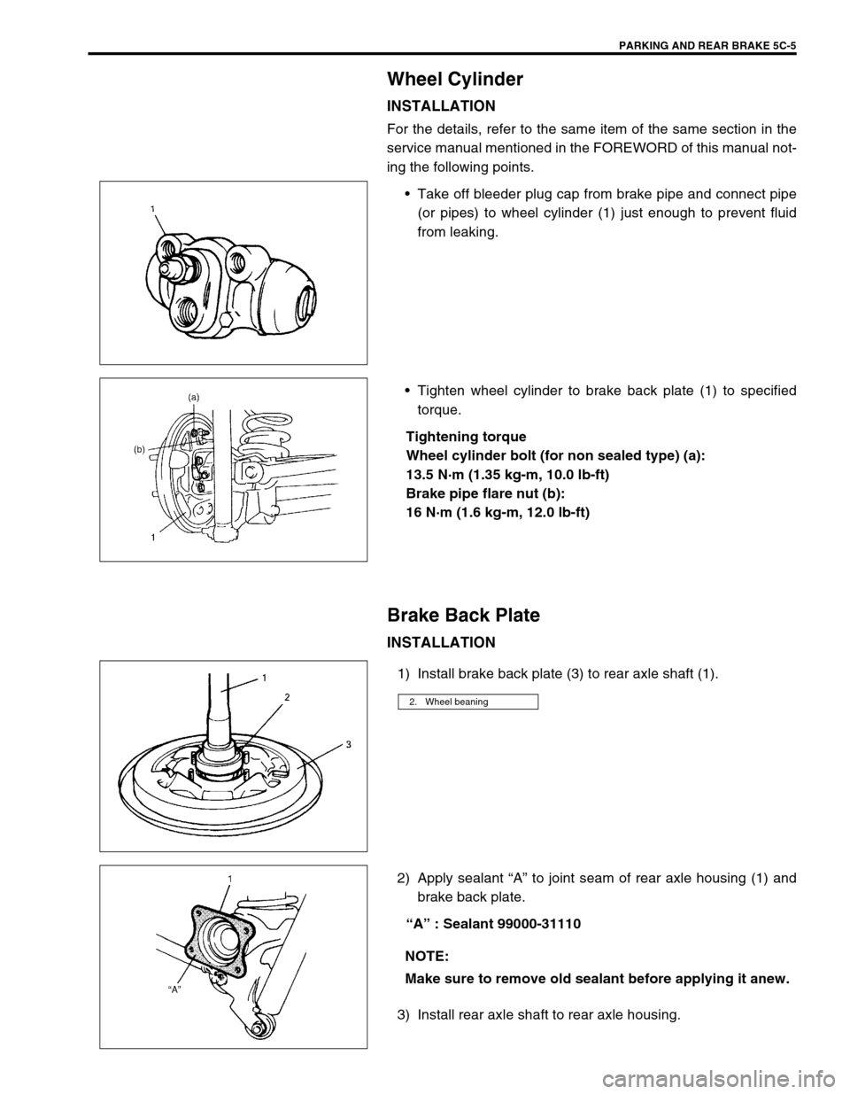
Take off bleeder plug cap from brake pipe and connect pipe
(or pipes) to wheel cylinder (1) just enough to prevent fluid
from leaking.
Tighten wheel cylinder to brake back plate (1) to specified
torque.
Tightening torque
Wheel cylinder bolt (for non sealed type) (a):
13.5 N·m (1.35 kg-m, 10.0 lb-ft)
Brake pipe flare nut (b):
16 N·m (1.6 kg-m, 12.0 lb-ft)
Brake Back Plate
INSTALLATION
1) Install brake back plate (3) to rear axle shaft (1).
2) Apply sealant “A” to joint seam of rear axle housing (1) and
brake back plate.
“A” : Sealant 99000-31110
3) Install rear axle shaft to rear axle housing.
2. Wheel beaning
NOTE:
Make sure to remove old sealant before applying it anew.
Page 123 of 656

5C-6 PARKING AND REAR BRAKE
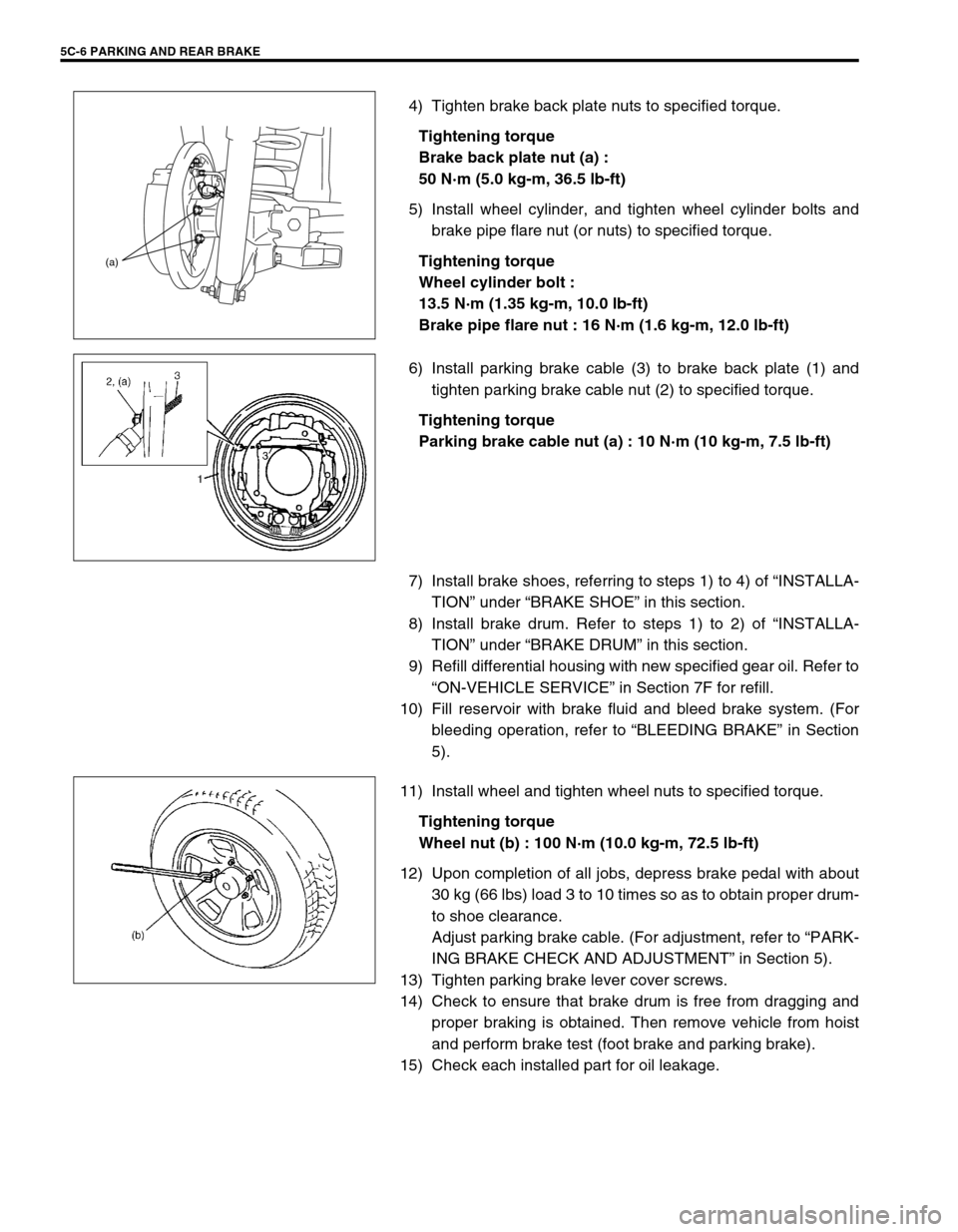
4) Tighten brake back plate nuts to specified torque.
Tightening torque
Brake back plate nut (a) :
50 N·m (5.0 kg-m, 36.5 lb-ft)
5) Install wheel cylinder, and tighten wheel cylinder bolts and
brake pipe flare nut (or nuts) to specified torque.
Tightening torque
Wheel cylinder bolt :
13.5 N·m (1.35 kg-m, 10.0 lb-ft)
Brake pipe flare nut : 16 N·m (1.6 kg-m, 12.0 lb-ft)
6) Install parking brake cable (3) to brake back plate (1) and
tighten parking brake cable nut (2) to specified torque.
Tightening torque
Parking brake cable nut (a) : 10 N·m (10 kg-m, 7.5 lb-ft)
7) Install brake shoes, referring to steps 1) to 4) of “INSTALLA-
TION” under “BRAKE SHOE” in this section.
8) Install brake drum. Refer to steps 1) to 2) of “INSTALLA-
TION” under “BRAKE DRUM” in this section.
9) Refill differential housing with new specified gear oil. Refer to
“ON-VEHICLE SERVICE” in Section 7F for refill.
10) Fill reservoir with brake fluid and bleed brake system. (For
bleeding operation, refer to “BLEEDING BRAKE” in Section
5).
11) Install wheel and tighten wheel nuts to specified torque.
Tightening torque
Wheel nut (b) : 100 N·m (10.0 kg-m, 72.5 lb-ft)
12) Upon completion of all jobs, depress brake pedal with about
30 kg (66 lbs) load 3 to 10 times so as to obtain proper drum-
to shoe clearance.
Adjust parking brake cable. (For adjustment, refer to “PARK-
ING BRAKE CHECK AND ADJUSTMENT” in Section 5).
13) Tighten parking brake lever cover screws.
14) Check to ensure that brake drum is free from dragging and
proper braking is obtained. Then remove vehicle from hoist
and perform brake test (foot brake and parking brake).
15) Check each installed part for oil leakage.
(a)
Page 124 of 656

PARKING AND REAR BRAKE 5C-7
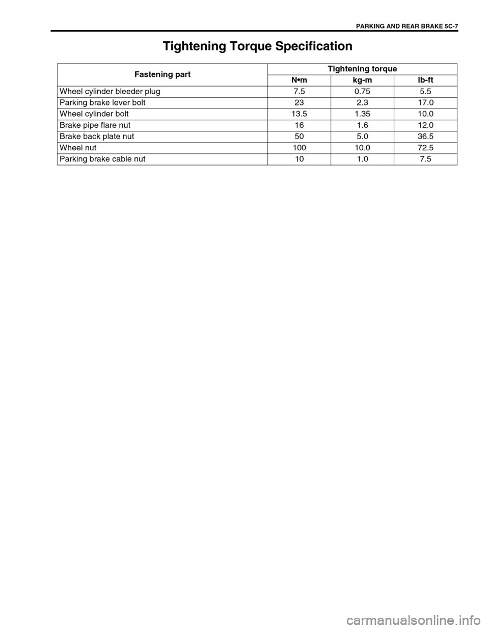
Tightening Torque Specification
Fastening partTightening torque
Nmkg-mlb-ft
Wheel cylinder bleeder plug 7.5 0.75 5.5
Parking brake lever bolt 23 2.3 17.0
Wheel cylinder bolt 13.5 1.35 10.0
Brake pipe flare nut 16 1.6 12.0
Brake back plate nut 50 5.0 36.5
Wheel nut 100 10.0 72.5
Parking brake cable nut 10 1.0 7.5
Page 126 of 656

ANTILOCK BRAKE SYSTEM (ABS) 5E2-1
5E2
SECTION 5E2
ANTILOCK BRAKE SYSTEM (ABS)
CONTENTS
General Description ..................................... 5E2-3
Components/Parts Location ....................... 5E2-3
ABS Hydraulic Unit/control Module
Assembly .................................................... 5E2-4
Self-diagnosis function ........................... 5E2-4
Fail-safe function .................................... 5E2-5
Diagnosis ...................................................... 5E2-5
Precautions in Diagnosing Troubles .......... 5E2-5
ABS Diagnostic Flow Table ........................ 5E2-6
ABS Warning Lamp Check ........................ 5E2-9
EBD Warning Lamp (Brake Warning Lamp)
Check ......................................................... 5E2-9
Diagnostic Trouble Code (DTC) Check
(Using ABS Warning Lamp) ..................... 5E2-10
Diagnostic Trouble Code (DTC) Check
(Using SUZUKI Scan Tool) ...................... 5E2-11
Diagnostic Trouble Code (DTC)
Clearance ................................................. 5E2-11
Diagnostic Trouble Code (DTC) Table ..... 5E2-12
System Circuit .......................................... 5E2-14Table-A ABS Warning Lamp Circuit Check
– Lamp Does Not Come “ON” at Ignition
Switch ON ................................................ 5E2-15
Table-B ABS Warning Lamp Circuit Check
– Lamp Comes “ON” Steady.................... 5E2-16
Table-C ABS Warning Lamp Circuit Check
– The Lamp Flashes Continuously While
Ignition Switch Is ON ................................ 5E2-17
Table-D Code (DTC) Is Not Outputted
Even with Diagnosis Switch Terminal
Connected to Ground............................... 5E2-18
Table-E EBD Warning Lamp (Brake
Warning Lamp) Check – Lamp Comes
“ON” Steady ............................................. 5E2-19
DTC C1015 (DTC 15) – G Sensor Circuit
and 4WD Lamp Circuit ............................. 5E2-20
DTC C1021 (DTC 21), DTC C1022
(DTC 22) – Right-Front Wheel Speed
Sensor Circuit or Sensor Ring ................. 5E2-22
DTC C1025 (DTC 25), DTC C1026
(DTC 26) – Left-Front Wheel Speed WARNING:
For vehicles equipped with Supplemental Restraint (Air Bag) System:
Service on and around the air bag system components or wiring must be performed only by an
authorized SUZUKI dealer. Refer to “Air Bag System Components and Wiring Location View” under
“General Description” in air bag system section in order to confirm whether you are performing ser-
vice on or near the air bag system components or wiring. Please observe all WARNINGS and “Ser-
vice Precautions” under “On-Vehicle Service” in air bag system section before performing service
on or around the air bag system components or wiring. Failure to follow WARNINGS could result in
unintentional activation of the system or could render the system inoperative. Either of these two
conditions may result in severe injury.
Technical service work must be started at least 90 seconds after the ignition switch is turned to the
“LOCK” position and the negative cable is disconnected from the battery. Otherwise, the system
may be activated by reserve energy in the Sensing and Diagnostic Module (SDM).
NOTE:
For the descriptions (items) not found in this section, refer to Section 5E1 of the Service Manual
mentioned in the FOREWORD of this manual.
All brake fasteners are important attaching parts in that they could affect the performance of vital
parts and systems, and/or could result in major repair expense. They must be replaced with one of
same part number or with an equivalent part if replacement becomes necessary. Do not use a
replacement part of lesser quality or substitute design. Torque values must be used as specified
during reassembly to assure proper retention of all parts. There is to be no welding as it may result
in extensive damage and weakening of the metal.
Page 127 of 656

5E2-2 ANTILOCK BRAKE SYSTEM (ABS)
Sensor Circuit or Sensor Ring ................. 5E2-22
DTC C1031 (DTC 31), DTC C1032
(DTC 32) – Right-Rear Wheel Speed
Sensor Circuit or Sensor Ring ................. 5E2-22
DTC C1035 (DTC 35), DTC C1036
(DTC 36) – Left-Rear Wheel Speed
Sensor Circuit or Sensor Ring ................. 5E2-22
DTC C1041 (DTC 41) – Right-Front Inlet
Solenoid Circuit ........................................ 5E2-24
DTC C1045 (DTC 45) – Left-Front Inlet
Solenoid Circuit ........................................ 5E2-24
DTC C1055 (DTC 55) – Rear Inlet
Solenoid Circuit ........................................ 5E2-24
DTC C1042 (DTC 42) – Right-Front
Outlet Solenoid Circuit ............................. 5E2-24
DTC C1046 (DTC 46) – Left-Front Outlet
Solenoid Circuit ........................................ 5E2-24
DTC C1056 (DTC 56) – Rear Outlet
Solenoid Circuit ........................................ 5E2-24
DTC C1057 (DTC 57) – Power Source Circuit....................................................... 5E2-25
DTC C1061 (DTC 61) – ABS Pump Motor
Circuit....................................................... 5E2-26
DTC C1063 (DTC 63) – ABS Fail-Safe
Relay Circuit ............................................ 5E2-27
DTC C1071 (DTC 71) – ABS Control
Module ..................................................... 5E2-28
On-Vehicle Service .................................... 5E2-29
Precautions .............................................. 5E2-29
ABS Hydraulic Unit Operation Check
(Using SUZUKI Scan Tool) ...................... 5E2-29
ABS Hydraulic Unit Operation Check
(Not Using Suzuki Scan Tool).................. 5E2-29
ABS Hydraulic Unit/Control Module
Assembly ................................................. 5E2-31
Rear Sensor Rotor (Retainer Ring) ......... 5E2-33
Tightening Torque Specification.............. 5E2-34
Special Tool ............................................... 5E2-34
Page 148 of 656

ANTILOCK BRAKE SYSTEM (ABS) 5E2-23
INSPECTION
Step Action Yes No
1 1) Disconnect applicable ABS wheel speed sensor coupler
with ignition switch OFF.
2) Measure resistance between terminals of ABS wheel
speed sensor. Refer to “FRONT WHEEL SPEED SEN-
SOR” and/or “REAR WHEEL SPEED SENSOR” in this
section.
Is measured resistance value as specified?Go to Step 2. Replace ABS wheel
speed sensor
assembly.
2 1) Turn ignition switch OFF.
2) Disconnect ABS hydraulic unit/control module connec-
tor.
3) Check for proper connection to ABS control module at
each sensor terminal.
4) If OK, then turn ignition switch ON and measure voltage
between sensor terminal of module connector and body
ground.
Is it 0V?Go to Step 3. ABS wheel speed
sensor circuit
shorted to power.
3 1) Turn ignition switch OFF.
2) Connect ABS wheel speed sensor coupler.
3) Measure resistance between the following points.
Both ABS hydraulic unit/control module connector termi-
nals of the corresponding sensor.
This check result should be the same as above Step 1.
Either terminal of wheel speed sensor coupler and body
ground.
This check result should be no continuity.
Are both check results OK?Go to Step 4. Circuit open or
shorted to ground.
4 1) Remove applicable ABS wheel speed sensor.
2) Check sensor for damage or foreign material attached.
Is it in good condition?Go to Step 5. Clean, repair or
replace.
5 Check front and/or rear sensor ring for the following
(remove rear drum as necessary) :
Rotor serration (teeth) neither missing nor damaged.
No foreign material being attached.
Rotor not being eccentric.
Wheel bearing free from excessive play.
Are they in good condition?Go to Step 6. Clean, repair or
replace.
6 1) Install ABS wheel speed sensor to knuckle.
2) Tighten sensor bolt to specified torque and check that
there is no clearance between sensor and knuckle.
Is it OK?Go to Step 7. Replace ABS wheel
speed sensor.
7 Referring to “Reference” of “FRONT WHEEL SPEED SEN-
SOR” and/or “Reference” of “REAR WHEEL SPEED SEN-
SOR” in this section, check output voltage or waveform.
Is specified voltage and/or waveform obtained?Substitute a known-
good ABS hydrau-
lic unit/control mod-
ule assembly and
recheck.Replace sensor and
recheck.