Page 157 of 656
5E2-32 ANTILOCK BRAKE SYSTEM (ABS)
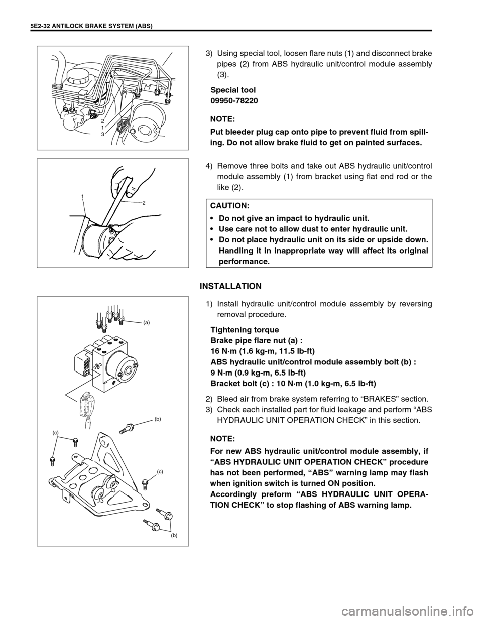
3) Using special tool, loosen flare nuts (1) and disconnect brake
pipes (2) from ABS hydraulic unit/control module assembly
(3).
Special tool
09950-78220
4) Remove three bolts and take out ABS hydraulic unit/control
module assembly (1) from bracket using flat end rod or the
like (2).
INSTALLATION
1) Install hydraulic unit/control module assembly by reversing
removal procedure.
Tightening torque
Brake pipe flare nut (a) :
16 N·m (1.6 kg-m, 11.5 lb-ft)
ABS hydraulic unit/control module assembly bolt (b) :
9 N·m (0.9 kg-m, 6.5 lb-ft)
Bracket bolt (c) : 10 N·m (1.0 kg-m, 6.5 lb-ft)
2) Bleed air from brake system referring to “BRAKES” section.
3) Check each installed part for fluid leakage and perform “ABS
HYDRAULIC UNIT OPERATION CHECK” in this section. NOTE:
Put bleeder plug cap onto pipe to prevent fluid from spill-
ing. Do not allow brake fluid to get on painted surfaces.
2
1
3
CAUTION:
Do not give an impact to hydraulic unit.
Use care not to allow dust to enter hydraulic unit.
Do not place hydraulic unit on its side or upside down.
Handling it in inappropriate way will affect its original
performance.
NOTE:
For new ABS hydraulic unit/control module assembly, if
“ABS HYDRAULIC UNIT OPERATION CHECK” procedure
has not been performed, “ABS” warning lamp may flash
when ignition switch is turned ON position.
Accordingly preform “ABS HYDRAULIC UNIT OPERA-
TION CHECK” to stop flashing of ABS warning lamp.
(b) (b) (a)
(c) (c)
Page 159 of 656
5E2-34 ANTILOCK BRAKE SYSTEM (ABS)
Tightening Torque Specification
Special Tool
Fastening partTightening torque
Nm kg-m lb-ft
Brake pipe flare nut : (a) 16 1.6 11.5
ABS hydraulic unit bolt : (b) 9 0.9 6.5
ABS hydraulic unit bracket bolt : (c) 10 1.0 7.5
Wheel speed sensor bolt (Front) : (d) 23 2.3 17.0
Wheel speed sensor bolt (Rear) : (e) 21 2.1 15.5
Parking lever assembly mounting bolt : (f) 23 2.3 17.0
(b) (b) (a)
(c) (c)
09950-78220 09931-76011 09931-76030
Flare nut wrench (10 mm) Tech 1A kit (SUZUKI scan
tool)
(See NOTE A.)Mass storage cartridge for
Tech 1A16/14 pin DLC cable for
Tech 1A
Page 165 of 656
6-1-4 ENGINE GENERAL INFORMATION AND DIAGNOSIS (H27 ENGINE)
When disconnecting couplers, don’t pull wire harness but
make sure to hold coupler itself. With lock type coupler, be
sure to unlock before disconnection. Attempt to disconnect
coupler without unlocking may result in damage to coupler.
When connecting lock type coupler, insert it till clicking
sound is heard and connect it securely.
Precaution on Fuel System Service
Work must be done with no smoking, in a well-ventilated area and away from any open flames.
As fuel feed line (between fuel pump and fuel pressure regulator) is still under high fuel pressure even after
engine was stopped, loosening or disconnecting fuel feed line directly may cause dangerous spout of fuel to
occur where loosened or disconnected. Before loosening or disconnecting fuel feed line, make sure to
release fuel pressure according to “FUEL PRESSURE RELIEF PROCEDURE” in this section.
A small amount of fuel may be released after the fuel line is disconnected.
In order to reduce the chance of personal injury, cover the fitting to be disconnected with a shop cloth. Put
that cloth in an approved container when disconnection is completed.
Never run engine with fuel pump relay disconnected when engine and exhaust system are hot.
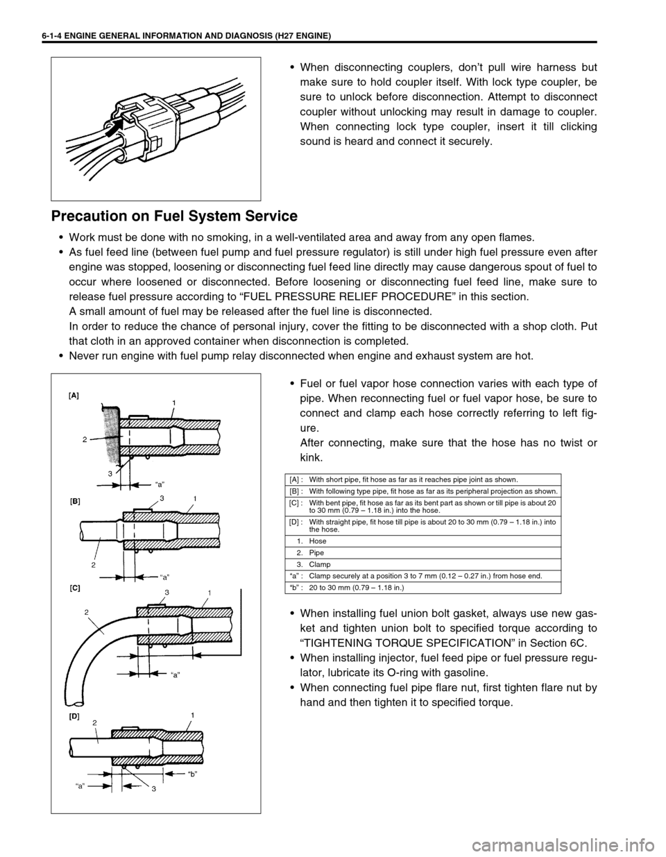
Fuel or fuel vapor hose connection varies with each type of
pipe. When reconnecting fuel or fuel vapor hose, be sure to
connect and clamp each hose correctly referring to left fig-
ure.
After connecting, make sure that the hose has no twist or
kink.
When installing fuel union bolt gasket, always use new gas-
ket and tighten union bolt to specified torque according to
“TIGHTENING TORQUE SPECIFICATION” in Section 6C.
When installing injector, fuel feed pipe or fuel pressure regu-
lator, lubricate its O-ring with gasoline.
When connecting fuel pipe flare nut, first tighten flare nut by
hand and then tighten it to specified torque.
[A] : With short pipe, fit hose as far as it reaches pipe joint as shown.
[B] : With following type pipe, fit hose as far as its peripheral projection as shown.
[C] : With bent pipe, fit hose as far as its bent part as shown or till pipe is about 20
to 30 mm (0.79 – 1.18 in.) into the hose.
[D] : With straight pipe, fit hose till pipe is about 20 to 30 mm (0.79 – 1.18 in.) into
the hose.
1. Hose
2. Pipe
3. Clamp
“a” : Clamp securely at a position 3 to 7 mm (0.12 – 0.27 in.) from hose end.
“b” : 20 to 30 mm (0.79 – 1.18 in.)
Page 187 of 656
6-1-26 ENGINE GENERAL INFORMATION AND DIAGNOSIS (H27 ENGINE)
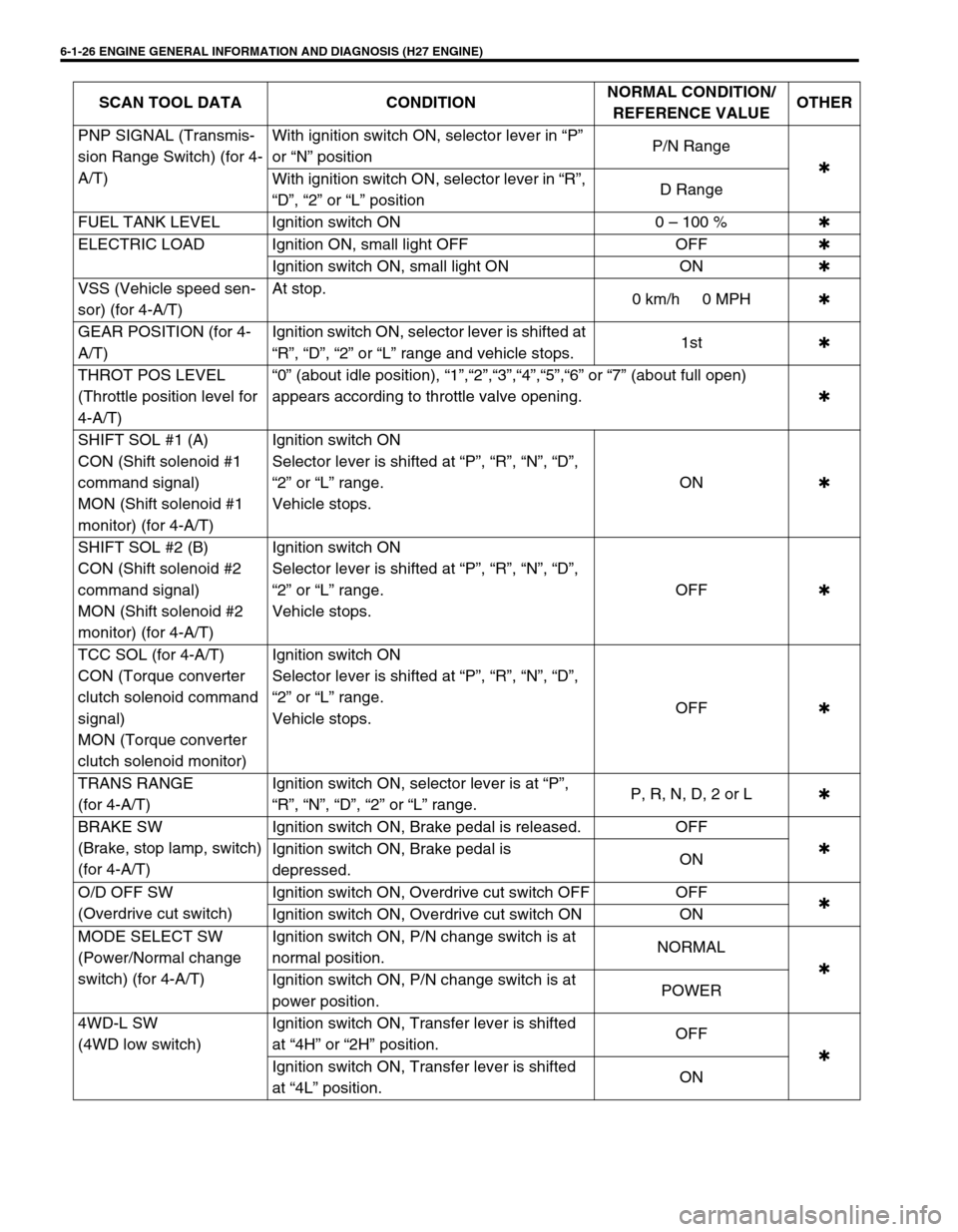
PNP SIGNAL (Transmis-
sion Range Switch) (for 4-
A/T)With ignition switch ON, selector lever in “P”
or “N” positionP/N Range
✱
With ignition switch ON, selector lever in “R”,
“D”, “2” or “L” positionD Range
FUEL TANK LEVEL Ignition switch ON 0 – 100 %✱
ELECTRIC LOAD Ignition ON, small light OFF OFF✱
Ignition switch ON, small light ON ON✱
VSS (Vehicle speed sen-
sor) (for 4-A/T)At stop.
0 km/h 0 MPH✱
GEAR POSITION (for 4-
A/T)Ignition switch ON, selector lever is shifted at
“R”, “D”, “2” or “L” range and vehicle stops.1st✱
THROT POS LEVEL
(Throttle position level for
4-A/T)“0” (about idle position), “1”,“2”,“3”,“4”,“5”,“6” or “7” (about full open)
appears according to throttle valve opening.✱
SHIFT SOL #1 (A)
CON (Shift solenoid #1
command signal)
MON (Shift solenoid #1
monitor) (for 4-A/T)Ignition switch ON
Selector lever is shifted at “P”, “R”, “N”, “D”,
“2” or “L” range.
Vehicle stops.ON✱
SHIFT SOL #2 (B)
CON (Shift solenoid #2
command signal)
MON (Shift solenoid #2
monitor) (for 4-A/T)Ignition switch ON
Selector lever is shifted at “P”, “R”, “N”, “D”,
“2” or “L” range.
Vehicle stops.OFF✱
TCC SOL (for 4-A/T)
CON (Torque converter
clutch solenoid command
signal)
MON (Torque converter
clutch solenoid monitor)Ignition switch ON
Selector lever is shifted at “P”, “R”, “N”, “D”,
“2” or “L” range.
Vehicle stops.OFF✱
TRANS RANGE
(for 4-A/T)Ignition switch ON, selector lever is at “P”,
“R”, “N”, “D”, “2” or “L” range.P, R, N, D, 2 or L✱
BRAKE SW
(Brake, stop lamp, switch)
(for 4-A/T)Ignition switch ON, Brake pedal is released. OFF
✱
Ignition switch ON, Brake pedal is
depressed.ON
O/D OFF SW
(Overdrive cut switch)Ignition switch ON, Overdrive cut switch OFF OFF
✱
Ignition switch ON, Overdrive cut switch ON ON
MODE SELECT SW
(Power/Normal change
switch) (for 4-A/T)Ignition switch ON, P/N change switch is at
normal position.NORMAL
✱
Ignition switch ON, P/N change switch is at
power position.POWER
4WD-L SW
(4WD low switch)Ignition switch ON, Transfer lever is shifted
at “4H” or “2H” position.OFF
✱
Ignition switch ON, Transfer lever is shifted
at “4L” position.ON SCAN TOOL DATA CONDITIONNORMAL CONDITION/
REFERENCE VALUEOTHER
Page 191 of 656
6-1-30 ENGINE GENERAL INFORMATION AND DIAGNOSIS (H27 ENGINE)
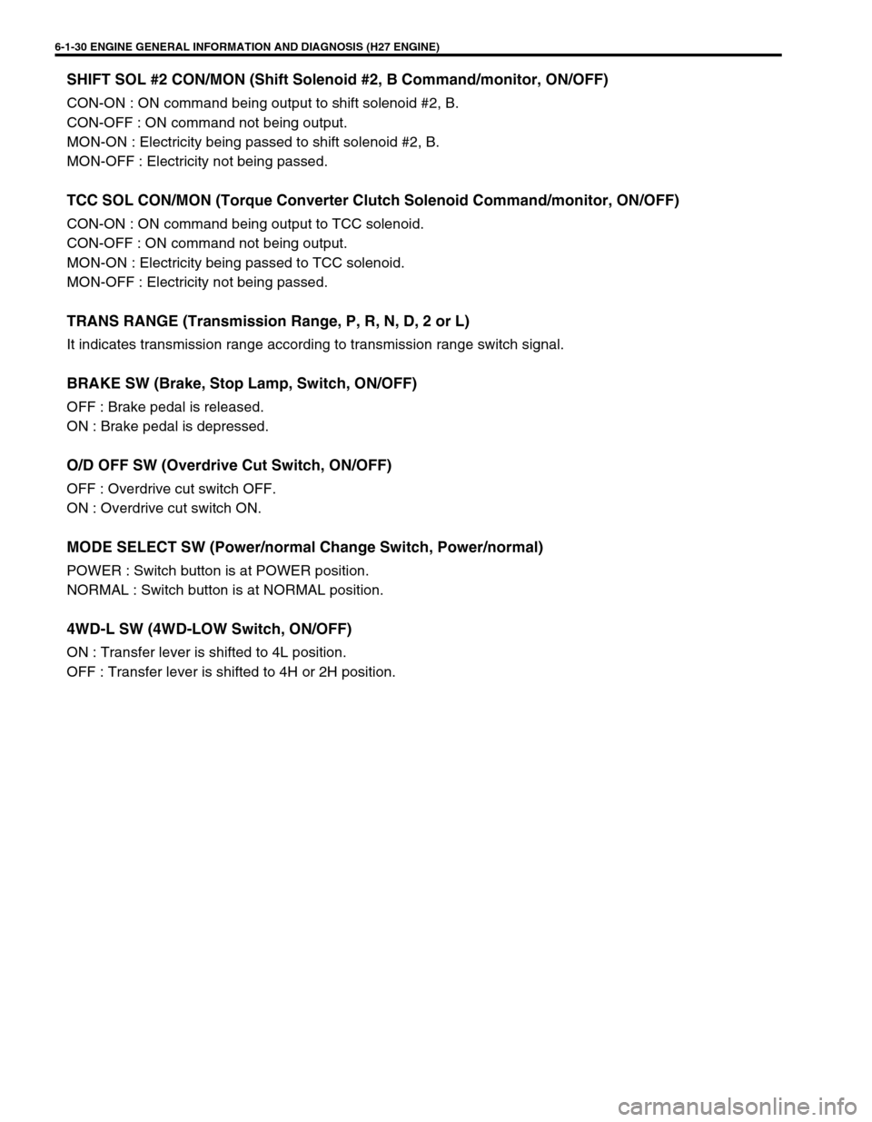
SHIFT SOL #2 CON/MON (Shift Solenoid #2, B Command/monitor, ON/OFF)
CON-ON : ON command being output to shift solenoid #2, B.
CON-OFF : ON command not being output.
MON-ON : Electricity being passed to shift solenoid #2, B.
MON-OFF : Electricity not being passed.
TCC SOL CON/MON (Torque Converter Clutch Solenoid Command/monitor, ON/OFF)
CON-ON : ON command being output to TCC solenoid.
CON-OFF : ON command not being output.
MON-ON : Electricity being passed to TCC solenoid.
MON-OFF : Electricity not being passed.
TRANS RANGE (Transmission Range, P, R, N, D, 2 or L)
It indicates transmission range according to transmission range switch signal.
BRAKE SW (Brake, Stop Lamp, Switch, ON/OFF)
OFF : Brake pedal is released.
ON : Brake pedal is depressed.
O/D OFF SW (Overdrive Cut Switch, ON/OFF)
OFF : Overdrive cut switch OFF.
ON : Overdrive cut switch ON.
MODE SELECT SW (Power/normal Change Switch, Power/normal)
POWER : Switch button is at POWER position.
NORMAL : Switch button is at NORMAL position.
4WD-L SW (4WD-LOW Switch, ON/OFF)
ON : Transfer lever is shifted to 4L position.
OFF : Transfer lever is shifted to 4H or 2H position.
Page 289 of 656
6A2-2 ENGINE MECHANICAL (H27 ENGINE)
On-Vehicle Service
Throttle Body and Intake Manifold
1. Air cleaner box 6. Intake manifold 11. Gasket 16. Throttle body bolt
2. Intake air hose 7. Intake manifold gasket 12. IAT sensor Tightening Torque
3. Intake air pipe 8. Throttle body assembly 13. MAF sensor Do not reuse
4. Surge tank pipe 9. Throttle body gasket 14. MAP sensor
5. Gasket 10. Intake collector 15. Throttle body nut
Page 293 of 656
6A2-6 ENGINE MECHANICAL (H27 ENGINE)
INSTALLATION
1) Install new intake manifold gaskets (1) to cylinder heads.
2) Install intake manifold (1).
Tighten bolts and nuts to specified torque.
Tightening torque
Intake manifold bolt and nut (a) :
23 N·m (2.3 kg-m, 16.5 lb-ft)
3) Install throttle body (2) to intake collector (1) with new throttle
body gasket.
Tighten bolts and nuts to specified torque.
Tightening torque
Throttle body bolt and nut (b) :
23 N·m (2.3 kg-m, 16.5 lb-ft)
4) Install EGR valve (1), EVAP canister purge valve (2), mani-
fold absolute pressure (MAP) sensor and each hoses to
intake collector and throttle body if removed.
Use new gasket, when installing IAC valve and EGR valve.
5) Install throttle body and intake collector assembly to intake
manifold with new intake collector gaskets.
1
(a)
(a)(a)
(a)
2 1
(b)
(b)
3. EVAP canister purge valve hose
2
1
3
Page 298 of 656
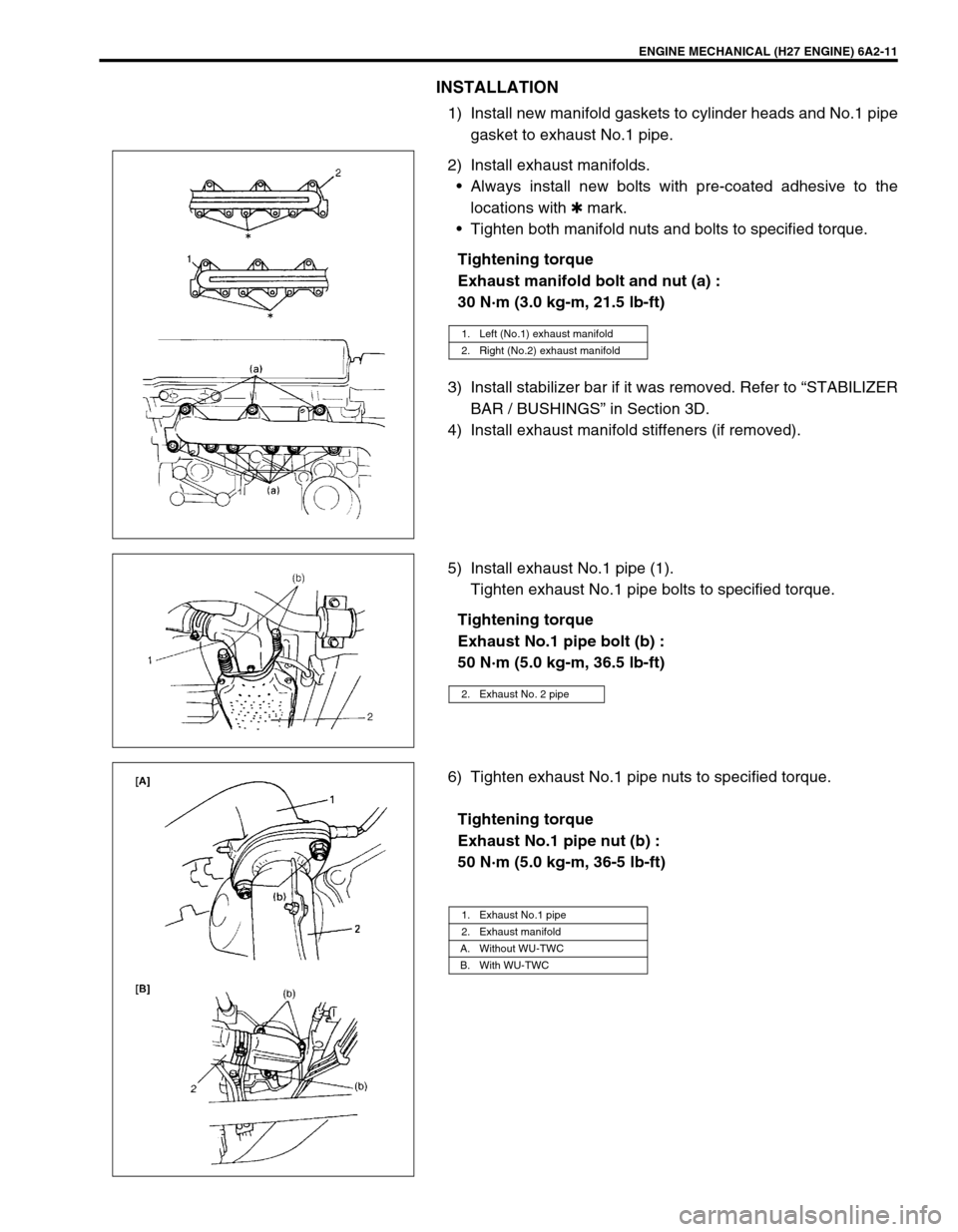
ENGINE MECHANICAL (H27 ENGINE) 6A2-11
INSTALLATION
1) Install new manifold gaskets to cylinder heads and No.1 pipe
gasket to exhaust No.1 pipe.
2) Install exhaust manifolds.
•Always install new bolts with pre-coated adhesive to the
locations with ✱ mark.
•Tighten both manifold nuts and bolts to specified torque.
Tightening torque
Exhaust manifold bolt and nut (a) :
30 N·m (3.0 kg-m, 21.5 lb-ft)
3) Install stabilizer bar if it was removed. Refer to “STABILIZER
BAR / BUSHINGS” in Section 3D.
4) Install exhaust manifold stiffeners (if removed).
5) Install exhaust No.1 pipe (1).
Tighten exhaust No.1 pipe bolts to specified torque.
Tightening torque
Exhaust No.1 pipe bolt (b) :
50 N·m (5.0 kg-m, 36.5 lb-ft)
6) Tighten exhaust No.1 pipe nuts to specified torque.
Tightening torque
Exhaust No.1 pipe nut (b) :
50 N·m (5.0 kg-m, 36-5 lb-ft)
1. Left (No.1) exhaust manifold
2. Right (No.2) exhaust manifold
2. Exhaust No. 2 pipe
1. Exhaust No.1 pipe
2. Exhaust manifold
A. Without WU-TWC
B. With WU-TWC