1999 SUZUKI GRAND VITARA abs
[x] Cancel search: absPage 156 of 656

ANTILOCK BRAKE SYSTEM (ABS) 5E2-31
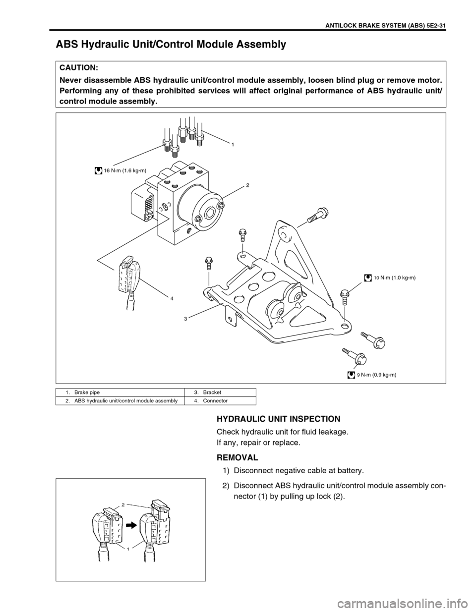
ABS Hydraulic Unit/Control Module Assembly
HYDRAULIC UNIT INSPECTION
Check hydraulic unit for fluid leakage.
If any, repair or replace.
REMOVAL
1) Disconnect negative cable at battery.
2) Disconnect ABS hydraulic unit/control module assembly con-
nector (1) by pulling up lock (2). CAUTION:
Never disassemble ABS hydraulic unit/control module assembly, loosen blind plug or remove motor.
Performing any of these prohibited services will affect original performance of ABS hydraulic unit/
control module assembly.
1. Brake pipe 3. Bracket
2. ABS hydraulic unit/control module assembly 4. Connector
4
32 1
16 N·m (1.6 kg-m)
10 N·m (1.0 kg-m)
9 N·m (0.9 kg-m)
Page 157 of 656

5E2-32 ANTILOCK BRAKE SYSTEM (ABS)
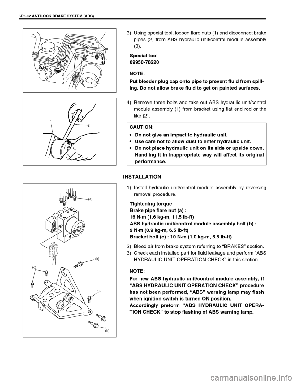
3) Using special tool, loosen flare nuts (1) and disconnect brake
pipes (2) from ABS hydraulic unit/control module assembly
(3).
Special tool
09950-78220
4) Remove three bolts and take out ABS hydraulic unit/control
module assembly (1) from bracket using flat end rod or the
like (2).
INSTALLATION
1) Install hydraulic unit/control module assembly by reversing
removal procedure.
Tightening torque
Brake pipe flare nut (a) :
16 N·m (1.6 kg-m, 11.5 lb-ft)
ABS hydraulic unit/control module assembly bolt (b) :
9 N·m (0.9 kg-m, 6.5 lb-ft)
Bracket bolt (c) : 10 N·m (1.0 kg-m, 6.5 lb-ft)
2) Bleed air from brake system referring to “BRAKES” section.
3) Check each installed part for fluid leakage and perform “ABS
HYDRAULIC UNIT OPERATION CHECK” in this section. NOTE:
Put bleeder plug cap onto pipe to prevent fluid from spill-
ing. Do not allow brake fluid to get on painted surfaces.
2
1
3
CAUTION:
Do not give an impact to hydraulic unit.
Use care not to allow dust to enter hydraulic unit.
Do not place hydraulic unit on its side or upside down.
Handling it in inappropriate way will affect its original
performance.
NOTE:
For new ABS hydraulic unit/control module assembly, if
“ABS HYDRAULIC UNIT OPERATION CHECK” procedure
has not been performed, “ABS” warning lamp may flash
when ignition switch is turned ON position.
Accordingly preform “ABS HYDRAULIC UNIT OPERA-
TION CHECK” to stop flashing of ABS warning lamp.
(b) (b) (a)
(c) (c)
Page 158 of 656

ANTILOCK BRAKE SYSTEM (ABS) 5E2-33
Rear Sensor Rotor (Retainer Ring)
REMOVAL
1) Remove rear axle shaft assembly. Refer to “REAR AXLE
SHAFT” in Section 3E.
2) In order to remove sensor rotor (retainer ring) (2) from shaft
(1), grind with a grinder one part “A” of the sensor rotor
(retainer ring) as shown till it becomes thin.
3) Break with a chisel (1) the thin ground sensor rotor (retainer
ring) (2), and it can be removed.
INSTALLATION
1) Press-fit sensor rotor (retainer ring) (1) as shown in the fig-
ure.
2) Install rear axle shaft assembly. Refer to “REAR AXLE
SHAFT” in Section 3E. CAUTION:
Cover vinyl sheet (3) or the like over wheel bearing so
that fine grains from grinding will not enter there.
Be careful not to go so far as to grind the retainer ring.
Page 159 of 656

5E2-34 ANTILOCK BRAKE SYSTEM (ABS)
Tightening Torque Specification
Special Tool
Fastening partTightening torque
Nm kg-m lb-ft
Brake pipe flare nut : (a) 16 1.6 11.5
ABS hydraulic unit bolt : (b) 9 0.9 6.5
ABS hydraulic unit bracket bolt : (c) 10 1.0 7.5
Wheel speed sensor bolt (Front) : (d) 23 2.3 17.0
Wheel speed sensor bolt (Rear) : (e) 21 2.1 15.5
Parking lever assembly mounting bolt : (f) 23 2.3 17.0
(b) (b) (a)
(c) (c)
09950-78220 09931-76011 09931-76030
Flare nut wrench (10 mm) Tech 1A kit (SUZUKI scan
tool)
(See NOTE A.)Mass storage cartridge for
Tech 1A16/14 pin DLC cable for
Tech 1A
Page 160 of 656

ANTILOCK BRAKE SYSTEM (ABS) 5E2-35
Tech 2 kit (SUZUKI scan
tool) (See NOTE B.)
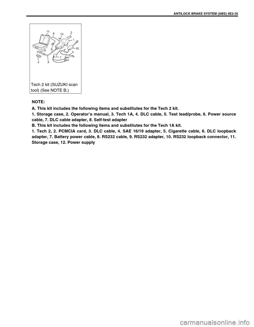
NOTE:
A. This kit includes the following items and substitutes for the Tech 2 kit.
1. Storage case, 2. Operator’s manual, 3. Tech 1A, 4. DLC cable, 5. Test lead/probe, 6. Power source
cable, 7. DLC cable adapter, 8. Self-test adapter
B. This kit includes the following items and substitutes for the Tech 1A kit.
1. Tech 2, 2. PCMCIA card, 3. DLC cable, 4. SAE 16/19 adapter, 5. Cigarette cable, 6. DLC loopback
adapter, 7. Battery power cable, 8. RS232 cable, 9. RS232 adapter, 10. RS232 loopback connector, 11.
Storage case, 12. Power supply
Page 161 of 656

5E2-36 ANTILOCK BRAKE SYSTEM (ABS)
Page 163 of 656

6-1-2 ENGINE GENERAL INFORMATION AND DIAGNOSIS (H27 ENGINE)
Table A-4 Malfunction Indicator Lamp
Check – MIL Does Not Flash or Just
Remains ON Even with Grounding
Diagnosis Switch Terminal (Vehicle with
Monitor Connector) ................................... 6-1-45
Table A-5 ECM (PCM) Power and Ground
Circuit Check – MIL Doesn’t Light at
Ignition Switch ON and Engine Doesn’t
Start Though It Is Cranked Up .................. 6-1-46
DTC P0100 (DTC No.33, 34) Mass Air
Flow Circuit Malfunction ............................ 6-1-48
DTC P0110 (DTC No.23, 25) Intake Air
Temp. (IAT) Circuit Malfunction ................ 6-1-50
DTC P0115 (DTC No.14, 15) Engine
Coolant Temp. Circuit Malfunction ............ 6-1-52
DTC P0120 (DTC No.21, 22) Throttle
Position Circuit Malfunction....................... 6-1-54
DTC P0121 Throttle Position Circuit
Range/Performance Problem ................... 6-1-56
DTC P0130 (DTC No.13) HO2S-1 (Bank 1)
Circuit Malfunction or No Activity
Detected.................................................... 6-1-58
DTC P0133 HO2S-1 (Bank 1) Circuit Slow
Response .................................................. 6-1-60
DTC P0135 HO2S-1 (Bank 1) Heater
Circuit Malfunction .................................... 6-1-61
DTC P0136 HO2S-2 (Bank 1) Circuit
Malfunction................................................ 6-1-63
DTC P0141 HO2S-2 (Bank 1) Heater
Circuit Malfunction .................................... 6-1-65
DTC P0150 (DTC No.26) HO2S-1 (Bank 2)
Circuit Malfunction or No Activity
Detected.................................................... 6-1-67
DTC P0153 HO2S-1 (Bank 2) Circuit Slow
Response .................................................. 6-1-69
DTC P0155 HO2S-1 (Bank 2) Heater
Circuit Malfunction .................................... 6-1-70
DTC P0156 HO2S-2 (Bank 2) Circuit
Malfunction................................................ 6-1-72
DTC P0161 HO2S-2 (Bank 2) Heater
Circuit Malfunction .................................... 6-1-74
DTC P0171/P0172 Fuel System Too
Lean/Rich (Bank 1) ................................... 6-1-76
DTC P0174/P0175 Fuel System Too
Lean/Rich (Bank 2) ................................... 6-1-78
DTC P0300/P0301/P0302/P0303/P0304/
P0305/P0306 Random Misfire/Cylinder 1
Misfire/Cylinder 2 Misfire/Cylinder 3 Misfire/
Cylinder 4 Misfire Detected/Cylinder 5
Misfire Detected/Cylinder 6 Misfire
Detected.................................................... 6-1-80
DTC P0325 (DTC No.43) Knock Sensor Circuit Malfunction ..................................... 6-1-82
DTC P0335 Crankshaft Position Sensor
Circuit Malfunction ..................................... 6-1-84
DTC P0340 (DTC No.42) Camshaft
Position Sensor Circuit Malfunction ........... 6-1-86
DTC P0400 Exhaust Gas Recirculation
Flow Malfunction ........................................ 6-1-89
DTC P0403 (DTC No.51) Exhaust Gas
Recirculation Circuit Malfunction ............... 6-1-92
DTC P0420 Catalyst System Efficiency
Below Threshold (Bank 1) ......................... 6-1-94
DTC P0430 Catalyst System Efficiency
Below Threshold (Bank 2) ......................... 6-1-96
DTC P0443 Evap Control System Purge
Control Valve Circuit Malfunction............... 6-1-98
Evap canister purge system
inspection ............................................. 6-1-100
Vacuum passage inspection ................ 6-1-100
Vacuum hose inspection ...................... 6-1-101
Evap canister purge valve and its
circuit inspection .................................. 6-1-101
Evap canister purge valve inspection .. 6-1-101
DTC P0460 Fuel Level Sensor Circuit
High Input ................................................ 6-1-103
DTC P0500 (DTC No.24) Vehicle Speed
Sensor Malfunction .................................. 6-1-105
DTC P0505 Idle Air Control System
Malfunction .............................................. 6-1-108
DTC P0601 (DTC No.71) Internal Control
Module Memory Check Sum Error .......... 6-1-110
DTC P1408 Manifold Absolute Pressure
Sensor Circuit Malfunction ....................... 6-1-111
DTC P1450/P1451 Barometric Pressure
Sensor Circuit Malfunction/Performance
Problem ................................................... 6-1-113
DTC P1500 Engine Starter Signal Circuit
Malfunction .............................................. 6-1-114
DTC P1510 Ecm Back-Up Power Supply
Malfunction .............................................. 6-1-115
Table B-1 Fuel Pump Circuit Inspection .. 6-1-116
Table B-2 Fuel Injectors and Circuit
Inspection ................................................ 6-1-117
Table B-3 Fuel Pressure Inspection ........ 6-1-119
Table B-4 Idle Air Control System
Inspection ................................................ 6-1-121
Table B-5 A/C Signal Circuits Inspection
(If Equipped) ............................................ 6-1-123
Table B-6 A/C Condenser Fan Motor
Relay Control System Inspection
(If Equipped) ............................................ 6-1-124
Special Tool ............................................... 6-1-125
Page 169 of 656

6-1-8 ENGINE GENERAL INFORMATION AND DIAGNOSIS (H27 ENGINE)
Priority of Freeze Frame Data
ECM (PCM) has 4 frames where the freeze frame data can be stored. The first frame stores the freeze frame
data of the malfunction which was detected first. However, the freeze frame data stored in this frame is updated
according to the priority described below. (If malfunction as described in the upper square “1” below is detected
while the freeze frame data in the lower square “2” has been stored, the freeze frame data “2” will be updated by
the freeze frame data “1”.)
In the 2nd through the 4th frames, the freeze frame data of each malfunction is stored in the order as the mal-
function is detected. These data are not updated regardless of the priority.
Shown in the table below are examples of how freeze frame data are stored when two or more malfunctions are
detected.
Freeze Frame Data Clearance
The freeze frame data is cleared at the same time as clearance of DTC.
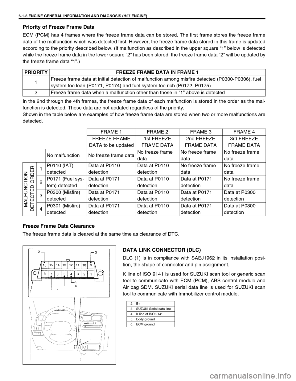
DATA LINK CONNECTOR (DLC)
DLC (1) is in compliance with SAEJ1962 in its installation posi-
tion, the shape of connector and pin assignment.
K line of ISO 9141 is used for SUZUKI scan tool or generic scan
tool to communicate with ECM (PCM), ABS control module and
Air bag SDM. SUZUKI serial data line is used for SUZUKI scan
tool to communicate with Immobilizer control module. PRIORITY FREEZE FRAME DATA IN FRAME 1
1Freeze frame data at initial detection of malfunction among misfire detected (P0300-P0306), fuel
system too lean (P0171, P0174) and fuel system too rich (P0172, P0175)
2 Freeze frame data when a malfunction other than those in “1” above is detected
FRAME 1 FRAME 2 FRAME 3 FRAME 4
FREEZE FRAME
DATA to be updated1st FREEZE
FRAME DATA2nd FREEZE
FRAME DATA3rd FREEZE
FRAME DATA
No malfunction No freeze frame dataNo freeze frame
dataNo freeze frame
dataNo freeze frame
data
MALFUNCTION
DETECTED ORDER
1P0110 (IAT)
detectedData at P0110
detectionData at P0110
detectionNo freeze frame
dataNo freeze frame
data
2P0171 (Fuel sys-
tem) detectedData at P0171
detectionData at P0110
detectionData at P0171
detectionNo freeze frame
data
3P0300 (Misfire)
detectedData at P0171
detectionData at P0110
detectionData at P0171
detectionData at P0300
detection
4P0301 (Misfire)
detectedData at P0171
detectionData at P0110
detectionData at P0171
detectionData at P0300
detection
2. B+
3. SUZUKI Serial data line
4. K line of ISO 9141
5. Body ground
6. ECM ground