1999 SUZUKI GRAND VITARA abs
[x] Cancel search: absPage 514 of 656
![SUZUKI GRAND VITARA 1999 2.G Owners Manual INSTRUMENTATION/DRIVER INFORMATION 8C-3
COMBINATION METER INTERNAL CIRCUITS
COMBINATION METER COUPLERS
[A] : Coupler A [B] : Coupler B [C] : Coupler C
1. To Cruise control module (if equipped) GRY/YE SUZUKI GRAND VITARA 1999 2.G Owners Manual INSTRUMENTATION/DRIVER INFORMATION 8C-3
COMBINATION METER INTERNAL CIRCUITS
COMBINATION METER COUPLERS
[A] : Coupler A [B] : Coupler B [C] : Coupler C
1. To Cruise control module (if equipped) GRY/YE](/manual-img/20/7583/w960_7583-513.png)
INSTRUMENTATION/DRIVER INFORMATION 8C-3
COMBINATION METER INTERNAL CIRCUITS
COMBINATION METER COUPLERS
[A] : Coupler A [B] : Coupler B [C] : Coupler C
1. To Cruise control module (if equipped) GRY/YEL 1. To door switch (drive side) BLK/BLU 1. To ground BLK
2. Blank–2. To transmission range switch
(A/T vehicle only, if equipped) LGRN/BLU 2. To ECM (PCM for A/T vehicle) BRN
3. To ignition switch BLK/WHT 3. To transmission range switch
(A/T vehicle only, if equipped) 2GRN/ORN 3. To ignition switch PPL/RED
4. Blank–4. To transmission range switch
(A/T vehicle only, if equipped) DYEL/GRN 4. To brake fluid level switch RED/BLK
5. To ABS control module (if equipped) BLU/ORN 5. To transmission range switch
(A/T vehicle only, if equipped) NORN/BLU 5. To parking brake switch PPL
6. To PCM (A/T vehicle only) GRY/BLU 6. To transmission range switch
(A/T vehicle only, if equipped) PORN/GRN 6. To seat belt switch GRY/RED
7. To ABS control module (if equipped) BRN 7. To transmission range switch
(A/T vehicle only, if equipped) RRED 7. To generator WHT/RED
8. To VSS BLU/YEL 8. To illumination control module RED/GRN 8. To engine oil pressure switch YEL/BLK
9. To combination switch GRN/RED 9. To PCM (A/T vehicle only) WHT/BLK 9. To combination switch RED/YEL
10. To air bag SDM BLU 10. To ECT sensor YEL/WHT 10. To ignition switch BLU/RED
11. To main fuse WHT/BLU 11. To fuel level gauge BLU/WHT
12. To fuse box WHT 12. To ground BLU/YEL
13. To combination switch RED 13. To combination switch GRN/YEL
14. To immobilizer control module
(if equipped)PPL
15. To ECM (PCM for A/T vehicle) PPL/YEL
16. To ECM (PCM for A/T vehicle) ORN/BLK
P R N D 2 LCRUISEPOWER4WDSPEED
METERTACHO
METERFUEL
METERTEMP.
METER
A-11
A-13 A-8 B-12 B-11 C-8 A-15 A-6 A-1 B-9 A-16 A-14 C-7 C-1 A-10 C-3 C-4 C-5 A-7 A-5 B-8 B-1B-10 C-2 A-12 A-3B-13 B-2 B-3 B-4 B-5 B- B-6 C-9 C-10 A-9ABS circuit EBD circuit Air bag circuit
or ABS or BRAKE
if equipped
or CHECK
ENGINE
NOTE:
Terminal arrangement of coupler viewed from harness side.
Page 548 of 656
BODY SERVICE 9-3
Body Structure
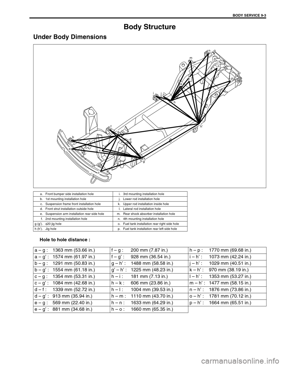
Under Body Dimensions
Hole to hole distance :
a. Front bumper side installation hole i. 3rd mounting installation hole
b. 1st mounting installation hole j. Lower rod installation hole
c. Suspension frame front installation hole k. Upper rod installation inside hole
d. Front strut installation outside hole l. Lateral rod installation hole
e. Suspension arm installation rear side hole m. Rear shock absorber installation hole
f. 2nd mounting installation hole n. 4th mounting installation hole
g (g’).φ
20 jig hole o. Fuel tank installation rear right side hole
h (h’). Jig hole p. Fuel tank installation rear left side hole
b
a
h’
e
f
g
d
g’
c
ij
h
o
p
n
m
l
k
a – g : 1363 mm (53.66 in.) f – g : 200 mm (7.87 in.) h – p : 1770 mm (69.68 in.)
a – g’ : 1574 mm (61.97 in.) f – g’ : 928 mm (36.54 in.) i – h’ : 1073 mm (42.24 in.)
b – g : 1291 mm (50.83 in.) g – h’ : 1488 mm (58.58 in.) j – h’ : 1029 mm (40.51 in.)
b – g’ : 1554 mm (61.18 in.) g’ – h’ : 1225 mm (48.23 in.) k – h’ : 970 mm (38.19 in.)
c – g : 1354 mm (53.31 in.) h – i : 181 mm (7.13 in.) l – h’ : 1353 mm (53.27 in.)
c – g’ : 1084 mm (42.68 in.) h – k : 606 mm (23.86 in.) m – h’ : 1477 mm (58.15 in.)
d – f : 1339 mm (52.72 in.) h – l : 1004 mm (39.53 in.) n – h’ : 1876 mm (73.86 in.)
d – g’ : 913 mm (35.94 in.) h – m : 1110 mm (43.70 in.) o – h’ : 1781 mm (70.12 in.)
e – g : 569 mm (22.40 in.) h – n : 1633 mm (64.29 in.) p – h’ : 1664 mm (65.51 in.)
e – g’ : 881 mm (34.68 in.) h – o : 1660 mm (65.35 in.)
Page 582 of 656

AIR BAG SYSTEM 10B-5
System Wiring Diagram
TERMINAL ARRANGEMENT OF SDM (VIEWED FROM HARNESS SIDE)
CONNECTOR “Q01” (SDM connector)
1
2
35
4 BLK/BLUBLU/BLK BLU/RED
BLK/WHT
BLU BLUGRN/RED
GRN GRNWHT WHT
GRN
YEL/RED
YEL
PNK
WHT
BRN
LT GRN
6
12V
5V 5V PPL/RED
ORN/GRN
ORN/BLU
YEL/GRN
YEL/BLUORN/GRN
ORN/BLU
YEL/GRN
YEL/BLUORN/GRN
ORN/BLU
YEL/GRN
YEL/BLUPPL/RED
87
“G27”
“E12”18 17“Q02”
“Q11” “Q12”9
10PPL
BLK
“Q04”
Q01-2
Q01-4
Q01-20Q01-7
Q01-8 Q01-10
Q01-9
Q01-12
Q01-11
Q01-5
Q01-6
Q01-15
Q01-17L1
L2 IG
SDL
Q01-19
SL+
Q01-18
SL-
Q01-13
SR+
Q01-14
SR-
DNS
GNDLA
PP- PP+DP- DP+P- P+D- D+
“Q07”
“Q06”“Q01”“Q05”
15
161413
12 11
[A]
[B]
[C]
“Q01” “Q12”,“G03”, “G27”,“E12”
“Q01”
BLK/WHT
“Q03”
“G03”
[A]: Shorting bar 6. Connection detection pin 14. Passenger air bag (inflator) module
[B]: Air bag harness 7. To ECM, TCM (if equipped) and ABS control
module (if equipped) 15. Driver seat belt pretensioner (if equipped)
[C]: Connector 8. To data link connector (DLC) 16. Passenger seat belt pretensioner (if equipped)
1. From main fuse 9.“AIR BAG” monitor coupler 17. LH Forward sensor
2. Ignition switch 10. Ground for air bag system 18. RH Forward sensor
3.“IG METER” fuse 11. SDM 19. To seat belt switch
4.“AIR BAG” warning lamp in combination meter 12. Contact coil assembly
5.“AIR BAG” fuse 13. Driver air bag (inflator) module
1. CONNECTOR “Q01” (SDM CONNECTOR)
TERMINAL CIRCUIT TERMINAL CIRCUIT
Q01-1–Q01-11
Driver pretensioner
(if equipped)Low
Q01-2“AIR BAG” warning lamp Q01-12 High
Q01-3–Q01-13
RH Forward sensorHigh
Q01-4 Ignition switch (power source) Q01-14 Low
Q01-5
Passenger pretensioner
(if equipped)High Q01-15 Diagnosis switch
Q01-6 Low Q01-16–
Q01-7 Passenger air bag (inflator)
moduleHigh Q01-17 Ground
Q01-8 Low Q01-18
LH Forward sensorLow
Q01-9 Driver air bag (inflator)
moduleLow Q01-19 High
Q01-10 High Q01-20 Data link connector (DLC)
Page 593 of 656
10B-16 AIR BAG SYSTEM
Table A - “AIR BAG” Warning Lamp Comes ON Steady
Table B - “AIR BAG” Warning Lamp Does Not Come ON
Table C - “AIR BAG” Warning Lamp Flashes
Table D - “AIR BAG” Warning Lamp Cannot Indicate Flashing Pattern of DTC
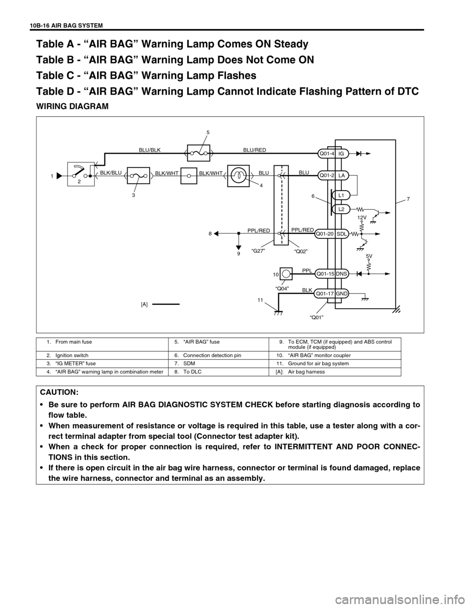
WIRING DIAGRAM
1. From main fuse 5.“AIR BAG” fuse 9. To ECM, TCM (if equipped) and ABS control
module (if equipped)
2. Ignition switch 6. Connection detection pin 10.“AIR BAG” monitor coupler
3.“IG METER” fuse 7. SDM 11. Ground for air bag system
4.“AIR BAG” warning lamp in combination meter 8. To DLC [A]: Air bag harness
1
2
34 BLK/BLUBLU/BLK BLU/RED
BLK/WHT BLK/WHTBLUBLU
6
PPL/REDPPL/RED
8
9
10
11
PPL
BLK
“Q04”
“Q01”
Q01-2
Q01-20
Q01-15
Q01-17L1
L2
SDL
DNS
GNDLA
Q01-4
IG
7
[A]
12V
5V
“G27”“Q02”
5
CAUTION:
Be sure to perform AIR BAG DIAGNOSTIC SYSTEM CHECK before starting diagnosis according to
flow table.
When measurement of resistance or voltage is required in this table, use a tester along with a cor-
rect terminal adapter from special tool (Connector test adapter kit).
When a check for proper connection is required, refer to INTERMITTENT AND POOR CONNEC-
TIONS in this section.
If there is open circuit in the air bag wire harness, connector or terminal is found damaged, replace
the wire harness, connector and terminal as an assembly.
Page 598 of 656
AIR BAG SYSTEM 10B-21
Table E - SDM Cannot Communicate through The Serial Data Circuit
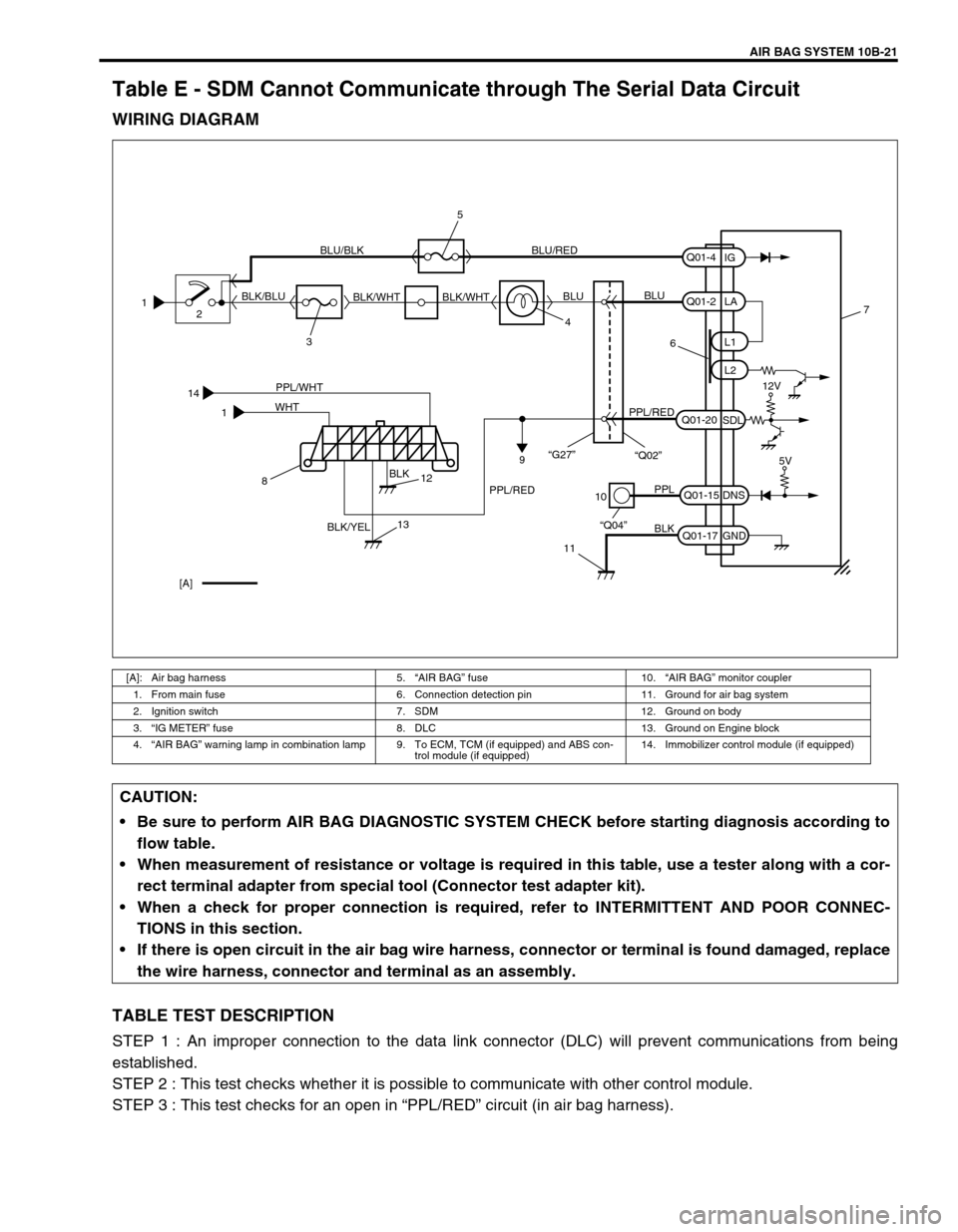
WIRING DIAGRAM
TABLE TEST DESCRIPTION
STEP 1 : An improper connection to the data link connector (DLC) will prevent communications from being
established.
STEP 2 : This test checks whether it is possible to communicate with other control module.
STEP 3 : This test checks for an open in “PPL/RED” circuit (in air bag harness).
[A]: Air bag harness 5.“AIR BAG” fuse 10.“AIR BAG” monitor coupler
1. From main fuse 6. Connection detection pin 11. Ground for air bag system
2. Ignition switch 7. SDM 12. Ground on body
3.“IG METER” fuse 8. DLC 13. Ground on Engine block
4.“AIR BAG” warning lamp in combination lamp 9. To ECM, TCM (if equipped) and ABS con-
trol module (if equipped)14. Immobilizer control module (if equipped)
14
1PPL/WHT
BLK
BLK/YEL WHT
10
11
PPL
BLK
“Q04”Q01-15
Q01-17DNS
GND7
[A]5V
812
13
1
2
34 BLK/BLUBLU/BLK BLU/RED
BLK/WHT BLK/WHTBLUBLU
6
PPL/REDPPL/RED
9
Q01-2
Q01-20L1
L2
SDLLA
Q01-4
IG
12V
“G27”
“Q02”
5
CAUTION:
Be sure to perform AIR BAG DIAGNOSTIC SYSTEM CHECK before starting diagnosis according to
flow table.
When measurement of resistance or voltage is required in this table, use a tester along with a cor-
rect terminal adapter from special tool (Connector test adapter kit).
When a check for proper connection is required, refer to INTERMITTENT AND POOR CONNEC-
TIONS in this section.
If there is open circuit in the air bag wire harness, connector or terminal is found damaged, replace
the wire harness, connector and terminal as an assembly.
Page 599 of 656
10B-22 AIR BAG SYSTEM
DIAGNOSTIC FLOW TABLE
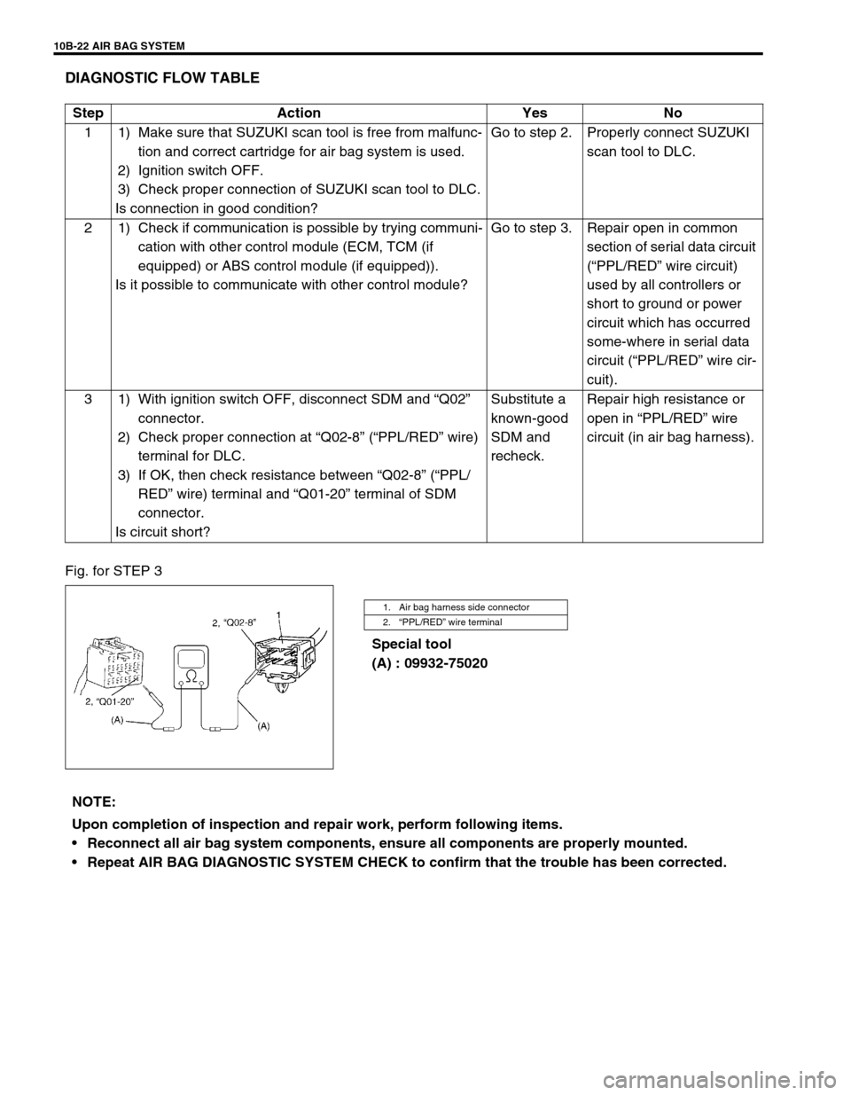
Fig. for STEP 3
Special tool
(A) : 09932-75020 Step Action Yes No
1 1) Make sure that SUZUKI scan tool is free from malfunc-
tion and correct cartridge for air bag system is used.
2) Ignition switch OFF.
3) Check proper connection of SUZUKI scan tool to DLC.
Is connection in good condition?Go to step 2. Properly connect SUZUKI
scan tool to DLC.
2 1) Check if communication is possible by trying communi-
cation with other control module (ECM, TCM (if
equipped) or ABS control module (if equipped)).
Is it possible to communicate with other control module?Go to step 3. Repair open in common
section of serial data circuit
(“PPL/RED” wire circuit)
used by all controllers or
short to ground or power
circuit which has occurred
some-where in serial data
circuit (“PPL/RED” wire cir-
cuit).
3 1) With ignition switch OFF, disconnect SDM and “Q02”
connector.
2) Check proper connection at “Q02-8” (“PPL/RED” wire)
terminal for DLC.
3) If OK, then check resistance between “Q02-8” (“PPL/
RED” wire) terminal and “Q01-20” terminal of SDM
connector.
Is circuit short?Substitute a
known-good
SDM and
recheck.Repair high resistance or
open in “PPL/RED” wire
circuit (in air bag harness).
1. Air bag harness side connector
2.“PPL/RED” wire terminal
NOTE:
Upon completion of inspection and repair work, perform following items.
Reconnect all air bag system components, ensure all components are properly mounted.
Repeat AIR BAG DIAGNOSTIC SYSTEM CHECK to confirm that the trouble has been corrected.
Page 624 of 656
AIR BAG SYSTEM 10B-47
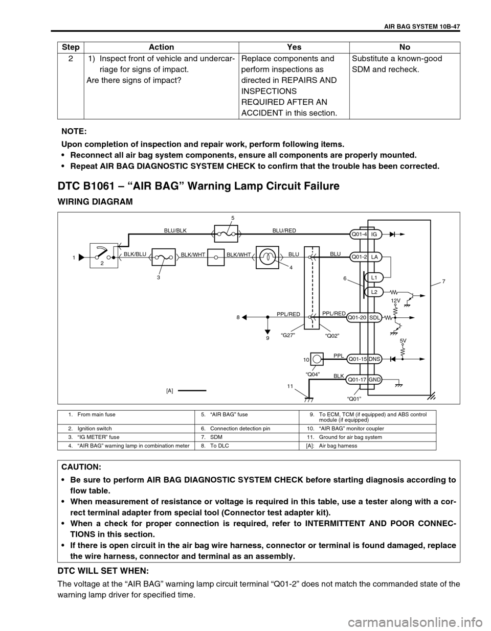
DTC B1061 – “AIR BAG” Warning Lamp Circuit Failure
WIRING DIAGRAM
DTC WILL SET WHEN:
The voltage at the “AIR BAG” warning lamp circuit terminal “Q01-2” does not match the commanded state of the
warning lamp driver for specified time.2 1) Inspect front of vehicle and undercar-
riage for signs of impact.
Are there signs of impact?Replace components and
perform inspections as
directed in REPAIRS AND
INSPECTIONS
REQUIRED AFTER AN
ACCIDENT in this section.Substitute a known-good
SDM and recheck. Step Action Yes No
NOTE:
Upon completion of inspection and repair work, perform following items.
Reconnect all air bag system components, ensure all components are properly mounted.
Repeat AIR BAG DIAGNOSTIC SYSTEM CHECK to confirm that the trouble has been corrected.
1. From main fuse 5.“AIR BAG” fuse 9. To ECM, TCM (if equipped) and ABS control
module (if equipped)
2. Ignition switch 6. Connection detection pin 10.“AIR BAG” monitor coupler
3.“IG METER” fuse 7. SDM 11. Ground for air bag system
4.“AIR BAG” warning lamp in combination meter 8. To DLC [A]: Air bag harness
1
2
34 BLK/BLUBLU/BLK BLU/RED
BLK/WHT BLK/WHTBLUBLU
6
PPL/REDPPL/RED
8
9
10
11
PPL
BLK
“Q04”
“Q01”
Q01-2
Q01-20
Q01-15
Q01-17L1
L2
SDL
DNS
GNDLA
Q01-4
IG
7
[A]
12V
5V
“G27”“Q02”
5
CAUTION:
Be sure to perform AIR BAG DIAGNOSTIC SYSTEM CHECK before starting diagnosis according to
flow table.
When measurement of resistance or voltage is required in this table, use a tester along with a cor-
rect terminal adapter from special tool (Connector test adapter kit).
When a check for proper connection is required, refer to INTERMITTENT AND POOR CONNEC-
TIONS in this section.
If there is open circuit in the air bag wire harness, connector or terminal is found damaged, replace
the wire harness, connector and terminal as an assembly.