Page 81 of 656
3C1-6 AIR BAG STEERING WHEEL AND COLUMN
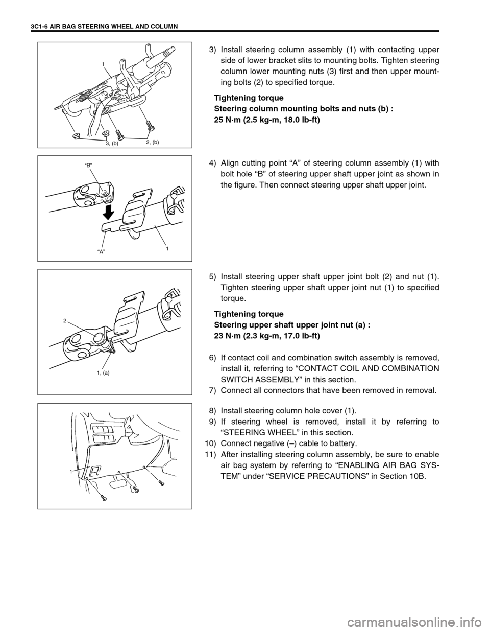
3) Install steering column assembly (1) with contacting upper
side of lower bracket slits to mounting bolts. Tighten steering
column lower mounting nuts (3) first and then upper mount-
ing bolts (2) to specified torque.
Tightening torque
Steering column mounting bolts and nuts (b) :
25 N·m (2.5 kg-m, 18.0 lb-ft)
4) Align cutting point “A” of steering column assembly (1) with
bolt hole “B” of steering upper shaft upper joint as shown in
the figure. Then connect steering upper shaft upper joint.
5) Install steering upper shaft upper joint bolt (2) and nut (1).
Tighten steering upper shaft upper joint nut (1) to specified
torque.
Tightening torque
Steering upper shaft upper joint nut (a) :
23 N·m (2.3 kg-m, 17.0 lb-ft)
6) If contact coil and combination switch assembly is removed,
install it, referring to “CONTACT COIL AND COMBINATION
SWITCH ASSEMBLY” in this section.
7) Connect all connectors that have been removed in removal.
8) Install steering column hole cover (1).
9) If steering wheel is removed, install it by referring to
“STEERING WHEEL” in this section.
10) Connect negative (–) cable to battery.
11) After installing steering column assembly, be sure to enable
air bag system by referring to “ENABLING AIR BAG SYS-
TEM” under “SERVICE PRECAUTIONS” in Section 10B.
1
3, (b)2, (b)
“B”
“A”
1
2
1, (a)
Page 82 of 656
AIR BAG STEERING WHEEL AND COLUMN 3C1-7
Steering Upper Shaft Assembly
REMOVAL
1) Turn steering wheel so that vehicle’s front tires are at
straight-ahead position.
2) Turn ignition switch to “LOCK” position and remove key.
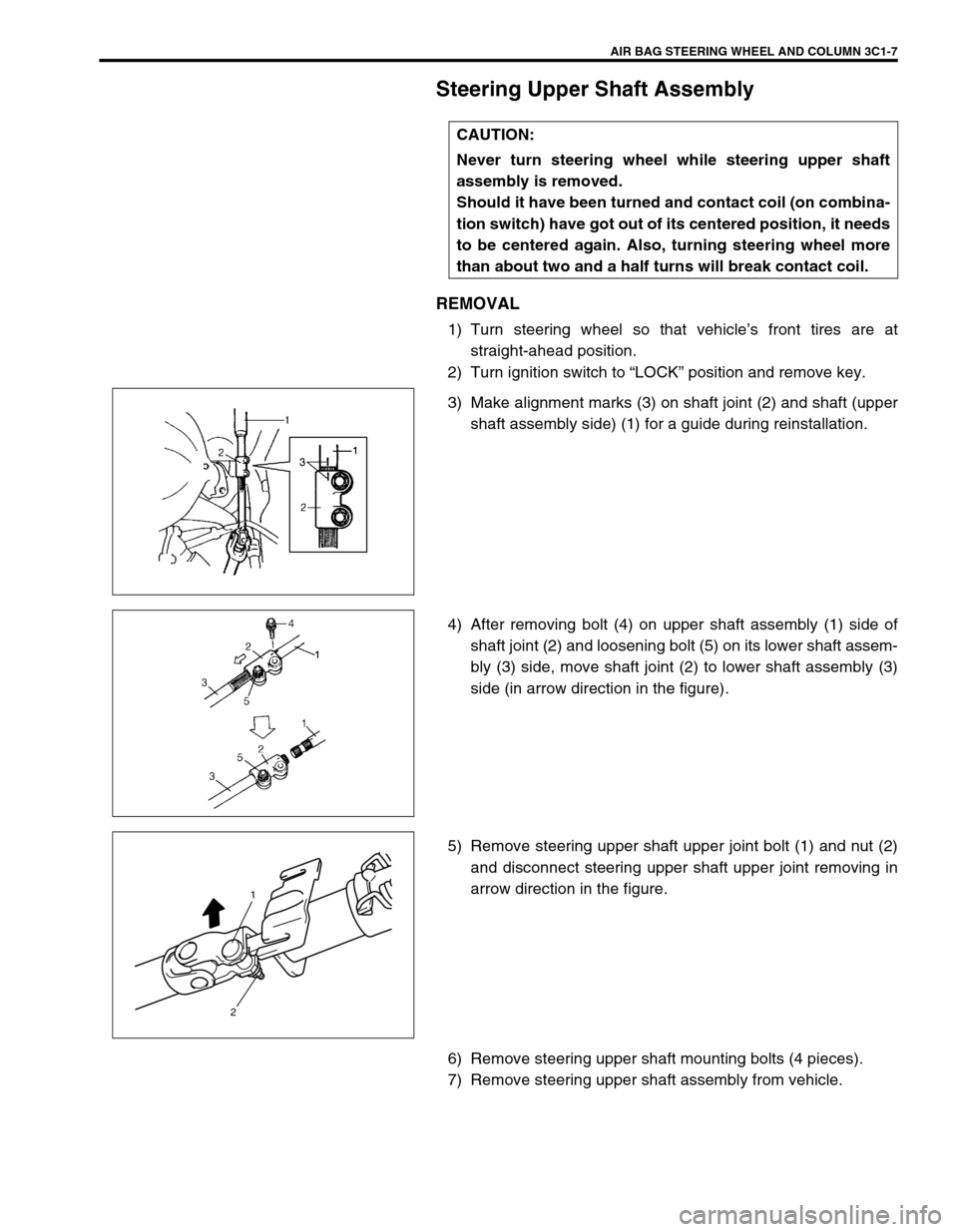
3) Make alignment marks (3) on shaft joint (2) and shaft (upper
shaft assembly side) (1) for a guide during reinstallation.
4) After removing bolt (4) on upper shaft assembly (1) side of
shaft joint (2) and loosening bolt (5) on its lower shaft assem-
bly (3) side, move shaft joint (2) to lower shaft assembly (3)
side (in arrow direction in the figure).
5) Remove steering upper shaft upper joint bolt (1) and nut (2)
and disconnect steering upper shaft upper joint removing in
arrow direction in the figure.
6) Remove steering upper shaft mounting bolts (4 pieces).
7) Remove steering upper shaft assembly from vehicle.CAUTION:
Never turn steering wheel while steering upper shaft
assembly is removed.
Should it have been turned and contact coil (on combina-
tion switch) have got out of its centered position, it needs
to be centered again. Also, turning steering wheel more
than about two and a half turns will break contact coil.
1
2
Page 84 of 656
AIR BAG STEERING WHEEL AND COLUMN 3C1-9
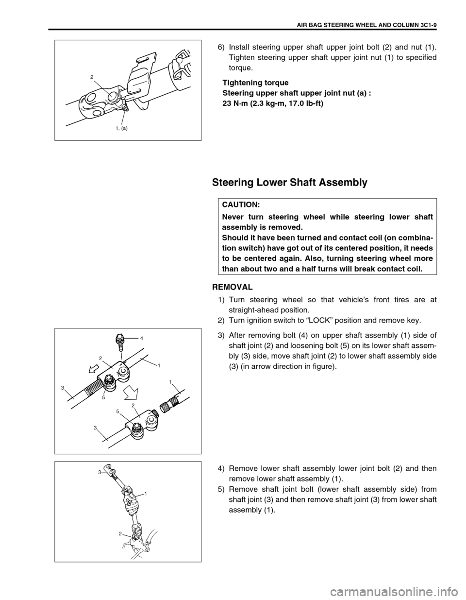
6) Install steering upper shaft upper joint bolt (2) and nut (1).
Tighten steering upper shaft upper joint nut (1) to specified
torque.
Tightening torque
Steering upper shaft upper joint nut (a) :
23 N·m (2.3 kg-m, 17.0 lb-ft)
Steering Lower Shaft Assembly
REMOVAL
1) Turn steering wheel so that vehicle’s front tires are at
straight-ahead position.
2) Turn ignition switch to “LOCK” position and remove key.
3) After removing bolt (4) on upper shaft assembly (1) side of
shaft joint (2) and loosening bolt (5) on its lower shaft assem-
bly (3) side, move shaft joint (2) to lower shaft assembly side
(3) (in arrow direction in figure).
4) Remove lower shaft assembly lower joint bolt (2) and then
remove lower shaft assembly (1).
5) Remove shaft joint bolt (lower shaft assembly side) from
shaft joint (3) and then remove shaft joint (3) from lower shaft
assembly (1).
1, (a) 2
CAUTION:
Never turn steering wheel while steering lower shaft
assembly is removed.
Should it have been turned and contact coil (on combina-
tion switch) have got out of its centered position, it needs
to be centered again. Also, turning steering wheel more
than about two and a half turns will break contact coil.
Page 90 of 656

REAR SUSPENSION 3E-1
3E
SECTION 3E
REAR SUSPENSION
CONTENTS
On-Vehicle Service......................................... 3E-1
Rear Axle Shaft and Wheel Bearing ............ 3E-1
Rear Axle Shaft Inner Oil Seal ..................... 3E-5
Rear Axle Housing ....................................... 3E-5Tightening Torque Specification .................. 3E-6
Required Service Material ............................. 3E-6
Special Tool .................................................... 3E-7
On-Vehicle Service
Rear Axle Shaft and Wheel Bearing
REMOVAL
1) Remove axle shaft from axle housing according to Step1) to
6) in the same section in the service manual mentioned in
the FOREWORD of this manual noting following points. NOTE:
For the descriptions (items) not found in this section, refer to the same section of the Service Man-
ual mentioned in the FOREWORD of this manual.
All suspension fasteners are an important attaching part in that it could affect the performance of
vital parts and systems, and/or could result in major repair expense. They must be replaced with
one of the same part number or with an equivalent part if replacement becomes necessary. Do not
use a replacement part of lesser quality or substitute design. Torque values must be used as speci-
fied during reassembly to assure proper retention of this part.
Never attempt to heat, quench or straighten any suspension part. Replace it with a new part, or
damage to the part may result.
Page 93 of 656
3E-4 REAR SUSPENSION
5) Apply grease “A” to axle shaft inner oil seal lip as shown in
the figure.
“A” : Grease 99000-25010
6) Apply water tight sealant “B” to mating surfaces of brake
back plate and rear axle hub (2).
“B” : Water tight sealant 99000-31110
7) Install rear axle shaft to rear axle housing and tighten bear-
ing retainer nuts to specified torque.
Rear axle shaft length “L”
Left side : 700.5 mm (27.6 in.)
Right side : 769.5 mm (30.3 in.)
Tightening torque
Bearing retainer nut (a) : 50 N·m (5.0 kg-m, 36.5 lb-ft)
8) Tighten wheel speed sensor bolt to specified torque (if
equipped with ABS).
Tightening torque
Wheel speed sensor bolt (b) : 21 N·m (2.1 kg-m, 15.5 lb-ft)
9) Refill rear axle housing with new specified gear oil.
Refer to “MAINTENANCE SERVICE” in Section 7F.
10) Install brake drum. Refer to “BRAKE DRUM” in Section 5C.
1. Axle housing
NOTE:
When installing rear axle shaft, be careful not to cause
damage to oil seal lip in axle housing.
(b)
Page 94 of 656
REAR SUSPENSION 3E-5
Rear Axle Shaft Inner Oil Seal
INSTALLATION
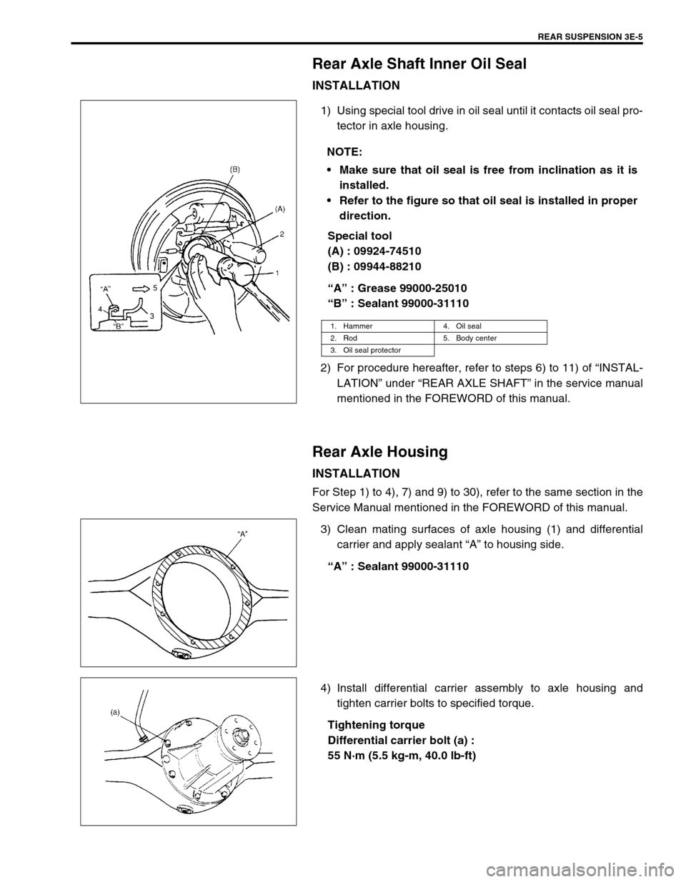
1) Using special tool drive in oil seal until it contacts oil seal pro-
tector in axle housing.
Special tool
(A) : 09924-74510
(B) : 09944-88210
“A” : Grease 99000-25010
“B” : Sealant 99000-31110
2) For procedure hereafter, refer to steps 6) to 11) of “INSTAL-
LATION” under “REAR AXLE SHAFT” in the service manual
mentioned in the FOREWORD of this manual.
Rear Axle Housing
INSTALLATION
For Step 1) to 4), 7) and 9) to 30), refer to the same section in the
Service Manual mentioned in the FOREWORD of this manual.
3) Clean mating surfaces of axle housing (1) and differential
carrier and apply sealant “A” to housing side.
“A” : Sealant 99000-31110
4) Install differential carrier assembly to axle housing and
tighten carrier bolts to specified torque.
Tightening torque
Differential carrier bolt (a) :
55 N·m (5.5 kg-m, 40.0 lb-ft) NOTE:
Make sure that oil seal is free from inclination as it is
installed.
Refer to the figure so that oil seal is installed in proper
direction.
1. Hammer 4. Oil seal
2. Rod 5. Body center
3. Oil seal protector
Page 95 of 656

3E-6 REAR SUSPENSION
5) Apply thread lock cement to thread of propeller shaft flange
bolt if reused. Install propeller shaft to joint flange aligning
match marks and torque flange nuts to specification.
“A” : Cement 99000-32110
Tightening torque
Propeller shaft nut (a) :
60 N·m (6.0 kg-m, 43.5 lb-ft)
Tightening Torque Specification
Required Service Material
Fastening partTightening torque
Nm kg-m lb-ft
Shock absorber nut 29 2.9 21.0
Shock absorber lower nut 85 8.5 61.5
Lower rod bolt and nut 100 10.0 72.5
Upper rod bolt and nut 100 10.0 72.5
Lateral rod bolt 100 10.0 72.5
Differential carrier bolt 55 5.5 40.0
Propeller shaft nut 60 6.0 43.5
Brake pipe flare nut 16 1.6 11.5
Bearing retainer nut 50 5.0 36.5
Differentiation gear oil filler & drain plug (filler plug) 50 5.0 36.5
Differentiation gear oil filler & drain plug (drain plug) 27 2.7 16.0
Wheel nut 100 10.0 72.5
Wheel speed sensor bolt 21 2.1 15.5
MaterialRecommended SUZUKI product
(Part Number)Use
Lithium grease SUZUKI SUPER GREASE A
(99000-25010)Oil seal lip
Brake fluid DOT 3Brake reservoir tank
Sealant SUZUKI BOND NO. 1215
(99000-31110)Joint seam of axle and brake back plate
Joint seam of bearing retainer and brake
back plate
Joint seam of differential carrier and axle
housing
Drain plug
Mating surface of oil seal and axle housing
Gear oil For gear oil information, refer to Section 7FDifferential gear (Rear axle housing)
Thread lock
cementTHREAD LOCK CEMENT SUPER 1322
(99000-32110)Rear propeller shaft flange bolts
Page 96 of 656
REAR SUSPENSION 3E-7
Special Tool
09921-57810 09924-74510 09926-88310 09927-18411
Counter shaft holder Bush remover handle Oil seal installer Universal puller
09942-15510 09943-35512 09944-88210
Sliding hammer Brake drum remover Bearing installer

