1999 SUZUKI GRAND VITARA oil
[x] Cancel search: oilPage 50 of 656
AIR CONDITIONING (OPTIONAL) 1B-25
On-Vehicle Service
Precaution
When servicing air conditioning system, the following rules must be observed.
Piping
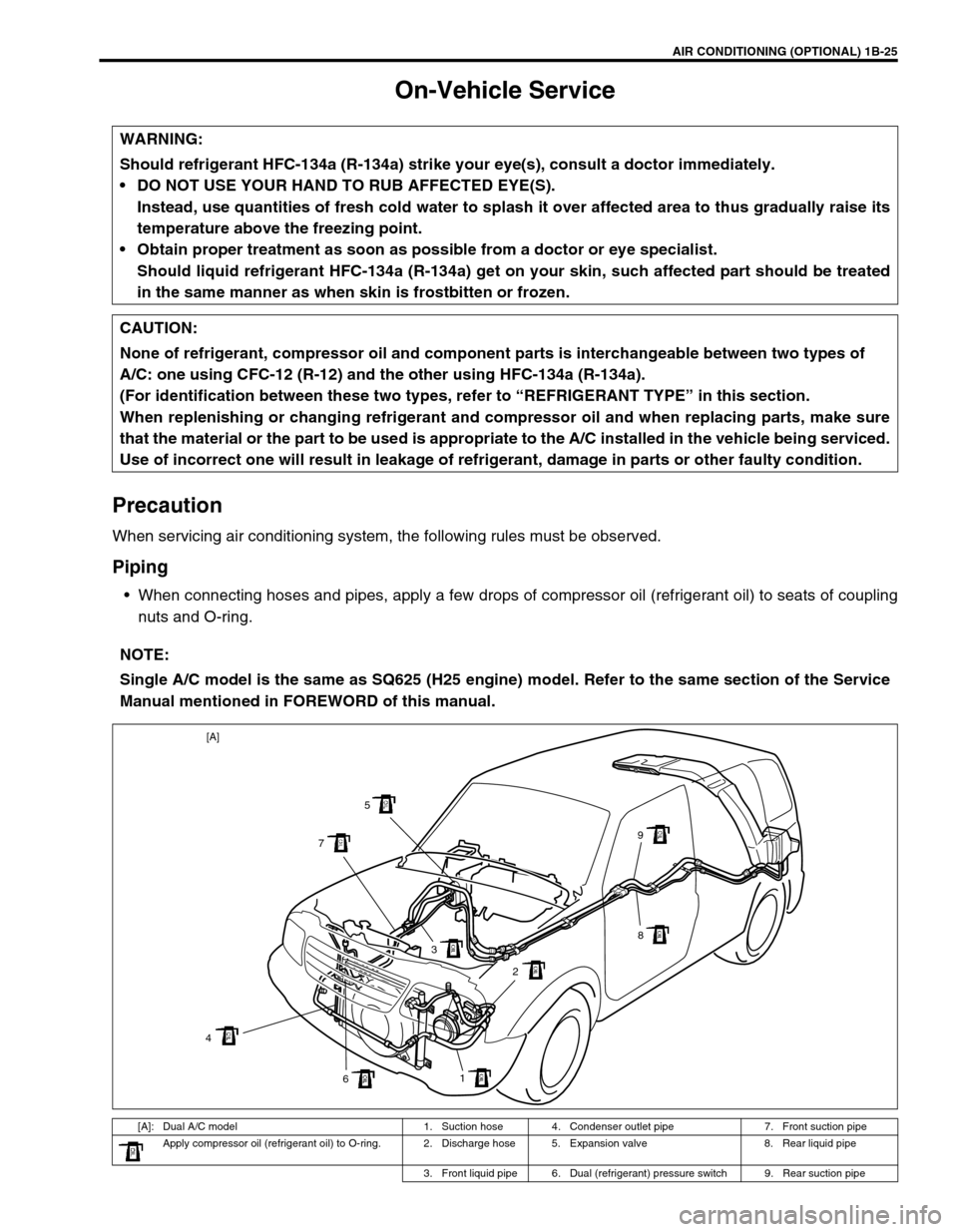
When connecting hoses and pipes, apply a few drops of compressor oil (refrigerant oil) to seats of coupling
nuts and O-ring. WARNING:
Should refrigerant HFC-134a (R-134a) strike your eye(s), consult a doctor immediately.
DO NOT USE YOUR HAND TO RUB AFFECTED EYE(S).
Instead, use quantities of fresh cold water to splash it over affected area to thus gradually raise its
temperature above the freezing point.
Obtain proper treatment as soon as possible from a doctor or eye specialist.
Should liquid refrigerant HFC-134a (R-134a) get on your skin, such affected part should be treated
in the same manner as when skin is frostbitten or frozen.
CAUTION:
None of refrigerant, compressor oil and component parts is interchangeable between two types of
A/C: one using CFC-12 (R-12) and the other using HFC-134a (R-134a).
(For identification between these two types, refer to “REFRIGERANT TYPE” in this section.
When replenishing or changing refrigerant and compressor oil and when replacing parts, make sure
that the material or the part to be used is appropriate to the A/C installed in the vehicle being serviced.
Use of incorrect one will result in leakage of refrigerant, damage in parts or other faulty condition.
NOTE:
Single A/C model is the same as SQ625 (H25 engine) model. Refer to the same section of the Service
Manual mentioned in FOREWORD of this manual.
[A]: Dual A/C model 1. Suction hose 4. Condenser outlet pipe 7. Front suction pipe
Apply compressor oil (refrigerant oil) to O-ring. 2. Discharge hose 5. Expansion valve 8. Rear liquid pipe
3. Front liquid pipe 6. Dual (refrigerant) pressure switch 9. Rear suction pipe
1
6 43 75
9
8
2 [A]
Page 51 of 656
1B-26 AIR CONDITIONING (OPTIONAL)
Never use heat for bending pipes. When bending a pipe, try to make its bending radius as slight as possible.
Keep internal parts of air conditioning free from moisture and dirt. When disconnecting any line from system,
install a blind plug or cap to the fitting immediately.
When tightening or loosening a fitting, use two wrenches, one for turning and the other for support.
Tighten flared nuts to specified torque.
Tightening torque
8 mm (0.31 in.) pipe : 13 N·m (1.3 kg-m, 9.5 lb-ft)
12.7 mm (0.5 in.) pipe : 22 N·m (2.2 kg-m, 16.0 lb-ft)
16 mm (0.63 in.) pipe : 33 N·m (3.3 kg-m, 24.0 lb-ft)
Route drain hose so that drained water does not make any contact to vehicle components.
Handling refrigerant HFC-134a (R-134a)
When handling refrigerant, always wear goggles to protect your eyes.
Avoid you direct contact to liquid refrigerant.
Do not heat refrigerant container higher than 40 °C (104 °F).
Do not discharge refrigerant into atmosphere.
Do not allow liquid refrigerant to touch bright metals. Refrigerant combined with moisture is corrosive and
will tarnish surfaces of bright metals including chrome.
After recovering refrigerant from system, the amount of compressor oil removed must be measured and the
same amount added to the system.
Refrigerant recovery
When discharging refrigerant out of A/C system, always recover it by using refrigerant recovery and recycling
equipment. Discharging refrigerant HFC-134a (R-134a) into atmosphere would cause adverse effect to environ-
ments.
Refrigerant charge
Charge a proper amount of refrigerant to A/C system according to charging procedure described in recovery,
evacuation and charging.NOTE:
When handling recovery and recycling equipment, be sure to follow the instruction manual for the
equipment.
CAUTION:
Do not perform an additional refrigerant charging to A/C system. This cause it to overcharge.
Page 52 of 656

AIR CONDITIONING (OPTIONAL) 1B-27
Replenishing compressor oil
When replacing air conditioning parts with new ones, it is neces-
sary to replenish oil by the amount supposedly remaining in each
part.
WHEN CHANGING GAS ONLY
When it is unavoidable to change gas without replacing any com-
ponent part for engine removal and installation or for some other
reason, replenish 20 cm
3 (20cc) oil. When replenishing gas only,
oil replenishment is not necessary.
WHEN REPLACING COMPRESSOR
Compressor oil is sealed in each new compressor by the amount
required for air conditioner cycle. Therefore, when using a new
compressor for replacement, drain oil from it by the amount calcu-
lated as follows.
“C” = “A” – “B”
“C” : Amount of oil to be drained
“A” : Amount of oil sealed in a new compressor
“B” : Amount of oil remaining in removed compressor
Amount of oil in new compressor :
Dual A/C model 140 cm
3 (140 cc)
Single A/C model 100 cm
3 (100 cc)
WHEN REPLACING OTHER PART
Amount of compressor oil : CAUTION:
Be sure to use HFC-134a (R-134a) compressor oil.
NOTE:
Compressor assembly supplied from factory is filled up
with the following amount of oil.
Replaced part Amount of compressor oil
to be replenished
Evaporator
25 cm
3 (25 cc)
Rear evaporator
(for dual A/C model)25 cm
3 (25 cc)
Condenser
15 cm
3 (15 cc)
Receiver/dryer
20 cm
3 (20 cc)
Hoses
10 cm
3 (10 cc) each
Pipes
10 cm
3 (10 cc) each
1. New compressor
2. Removed compressor
3. Excess oil (A–B)
Page 53 of 656
1B-28 AIR CONDITIONING (OPTIONAL)
Rear A/C Unit (Rear A/C Evaporator)
REMOVAL
1) Disconnect negative (–) cable at battery.
2) Recover refrigerant by using recovery and recycling equip-
ment. Be sure to follow the instruction manual for the equip-
ment.
The amount of compressor oil removed must be measured
and the same amount added to the system.
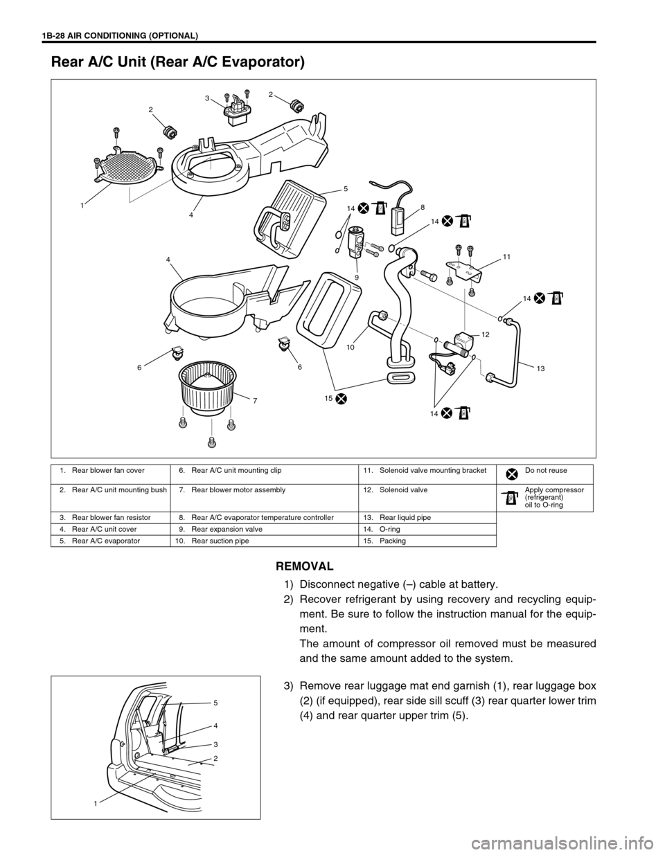
3) Remove rear luggage mat end garnish (1), rear luggage box
(2) (if equipped), rear side sill scuff (3) rear quarter lower trim
(4) and rear quarter upper trim (5).
1. Rear blower fan cover 6. Rear A/C unit mounting clip 11. Solenoid valve mounting bracket Do not reuse
2. Rear A/C unit mounting bush 7. Rear blower motor assembly 12. Solenoid valve Apply compressor
(refrigerant)
oil to O-ring
3. Rear blower fan resistor 8. Rear A/C evaporator temperature controller 13. Rear liquid pipe
4. Rear A/C unit cover 9. Rear expansion valve 14. O-ring
5. Rear A/C evaporator 10. Rear suction pipe 15. Packing
6
7
15
10
14
12
13
14
14
14
11
8
9
4
6
5
41
232
5
4
3
2
1
Page 54 of 656
AIR CONDITIONING (OPTIONAL) 1B-29
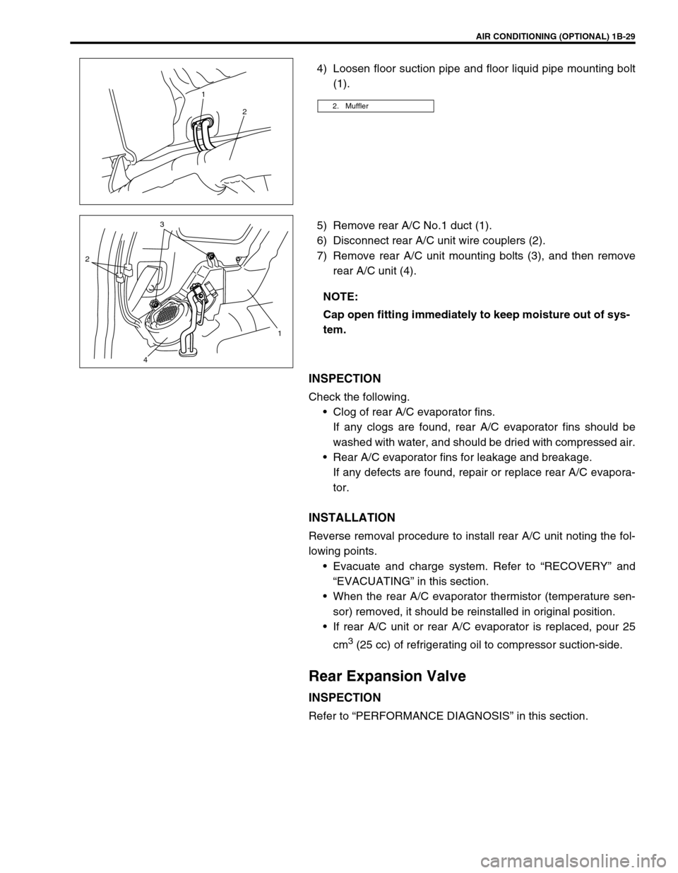
4) Loosen floor suction pipe and floor liquid pipe mounting bolt
(1).
5) Remove rear A/C No.1 duct (1).
6) Disconnect rear A/C unit wire couplers (2).
7) Remove rear A/C unit mounting bolts (3), and then remove
rear A/C unit (4).
INSPECTION
Check the following.
Clog of rear A/C evaporator fins.
If any clogs are found, rear A/C evaporator fins should be
washed with water, and should be dried with compressed air.
Rear A/C evaporator fins for leakage and breakage.
If any defects are found, repair or replace rear A/C evapora-
tor.
INSTALLATION
Reverse removal procedure to install rear A/C unit noting the fol-
lowing points.
Evacuate and charge system. Refer to “RECOVERY” and
“EVACUATING” in this section.
When the rear A/C evaporator thermistor (temperature sen-
sor) removed, it should be reinstalled in original position.
If rear A/C unit or rear A/C evaporator is replaced, pour 25
cm
3 (25 cc) of refrigerating oil to compressor suction-side.
Rear Expansion Valve
INSPECTION
Refer to “PERFORMANCE DIAGNOSIS” in this section.
2. Muffler
1
2
NOTE:
Cap open fitting immediately to keep moisture out of sys-
tem.
23
1
4
Page 56 of 656
AIR CONDITIONING (OPTIONAL) 1B-31
INSPECTION
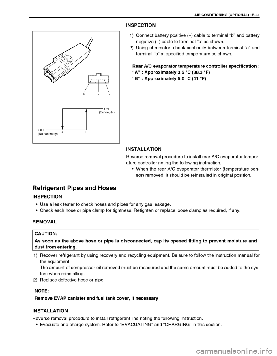
1) Connect battery positive (+) cable to terminal “b” and battery
negative (–) cable to terminal “c” as shown.
2) Using ohmmeter, check continuity between terminal “a” and
terminal “b” at specified temperature as shown.
Rear A/C evaporator temperature controller specification :
“A” : Approximately 3.5 °C (38.3 °F)
“B” : Approximately 5.0 °C (41 °F)
INSTALLATION
Reverse removal procedure to install rear A/C evaporator temper-
ature controller noting the following instruction.
When the rear A/C evaporator thermistor (temperature sen-
sor) removed, it should be reinstalled in original position.
Refrigerant Pipes and Hoses
INSPECTION
Use a leak tester to check hoses and pipes for any gas leakage.
Check each hose or pipe clamp for tightness. Retighten or replace loose clamp as required, if any.
REMOVAL
1) Recover refrigerant by using recovery and recycling equipment. Be sure to follow the instruction manual for
the equipment.
The amount of compressor oil removed must be measured and the same amount must be added to the sys-
tem when reinstalling.
2) Replace defective hose or pipe.
INSTALLATION
Reverse removal procedure to install refrigerant line noting the following instruction.
Evacuate and charge system. Refer to “EVACUATING” and “CHARGING” in this section.
CAUTION:
As soon as the above hose or pipe is disconnected, cap its opened fitting to prevent moisture and
dust from entering.
NOTE:
Remove EVAP canister and fuel tank cover, if necessary
Page 63 of 656
1B-38 AIR CONDITIONING (OPTIONAL)
Compressor Assembly
INSPECTION
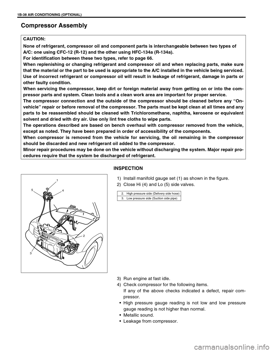
1) Install manifold gauge set (1) as shown in the figure.
2) Close Hi (4) and Lo (5) side valves.
3) Run engine at fast idle.
4) Check compressor for the following items.
If any of the above checks indicated a defect, repair com-
pressor.
High pressure gauge reading is not low and low pressure
gauge reading is not higher than normal.
Metallic sound.
Leakage from compressor. CAUTION:
None of refrigerant, compressor oil and component parts is interchangeable between two types of
A/C: one using CFC-12 (R-12) and the other using HFC-134a (R-134a).
For identification between these two types, refer to page 66.
When replenishing or changing refrigerant and compressor oil and when replacing parts, make sure
that the material or the part to be used is appropriate to the A/C installed in the vehicle being serviced.
Use of incorrect refrigerant or compressor oil will result in leakage of refrigerant, damage in parts or
other faulty condition.
When servicing the compressor, keep dirt or foreign material away from getting on or into the com-
pressor parts and system. Clean tools and a clean work area are important for proper service.
The compressor connection and the outside of the compressor should be cleaned before any “On-
vehicle” repair or before removal of the compressor. The parts must be kept clean at all times and any
parts to be reassembled should be cleaned with Trichloromethane, naphtha, kerosene or equivalent
solvent and dried with dry air. Use only lint free cloths to wipe parts.
The operations described are based on bench overhaul with compressor removed from the vehicle,
except as noted. They have been prepared in order of accessibility of the components.
When compressor is removed from the vehicle for servicing, the oil remaining in the compressor
should be discarded and new refrigerant oil added to the compressor.
Minor repair procedures may be done on the vehicle without discharging the system. Major repair pro-
cedures require that the system be discharged of refrigerant.
2. High pressure side (Delivery side hose)
3. Low pressure side (Suction side pipe)
1
4 5
2
3
Page 64 of 656
AIR CONDITIONING (OPTIONAL) 1B-39
REMOVAL
1) Run engine at idle with A/C ON for 10 minutes.
2) Disconnect negative (–) cable at battery.
3) Recover refrigerant from refrigeration system using recovery
and recycling equipment.
4) Remove P/S pump referring to step 4) to 7) of “REMOVAL”
under “P/S PUMP” in Section 3B1.
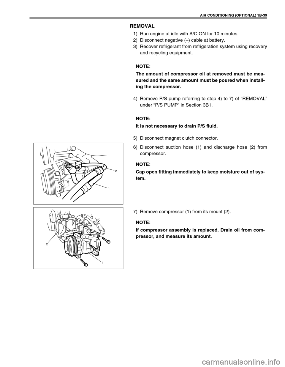
5) Disconnect magnet clutch connector.
6) Disconnect suction hose (1) and discharge hose (2) from
compressor.
7) Remove compressor (1) from its mount (2).NOTE:
The amount of compressor oil at removed must be mea-
sured and the same amount must be poured when install-
ing the compressor.
NOTE:
It is not necessary to drain P/S fluid.
NOTE:
Cap open fitting immediately to keep moisture out of sys-
tem.
2
1
NOTE:
If compressor assembly is replaced. Drain oil from com-
pressor, and measure its amount.
1 2