1999 SUZUKI GRAND VITARA oil
[x] Cancel search: oilPage 100 of 656

FRONT DRIVE SHAFT/SHAFT BEARING, OIL SEAL 4A2-1
4A2
SECTION 4A2
FRONT DRIVE SHAFT/SHAFT BEARING,
OIL SEAL
CONTENTS
On-Vehicle Service....................................... 4A2-2
Drive Shaft ................................................. 4A2-2Required Service Material ........................... 4A2-4
NOTE:
For the descriptions (items) not found in this section, refer to the same section of the Service Manual
mentioned in the FOREWORD of this manual.
Page 101 of 656
4A2-2 FRONT DRIVE SHAFT/SHAFT BEARING, OIL SEAL
On-Vehicle Service
Drive Shaft
ASSEMBLY
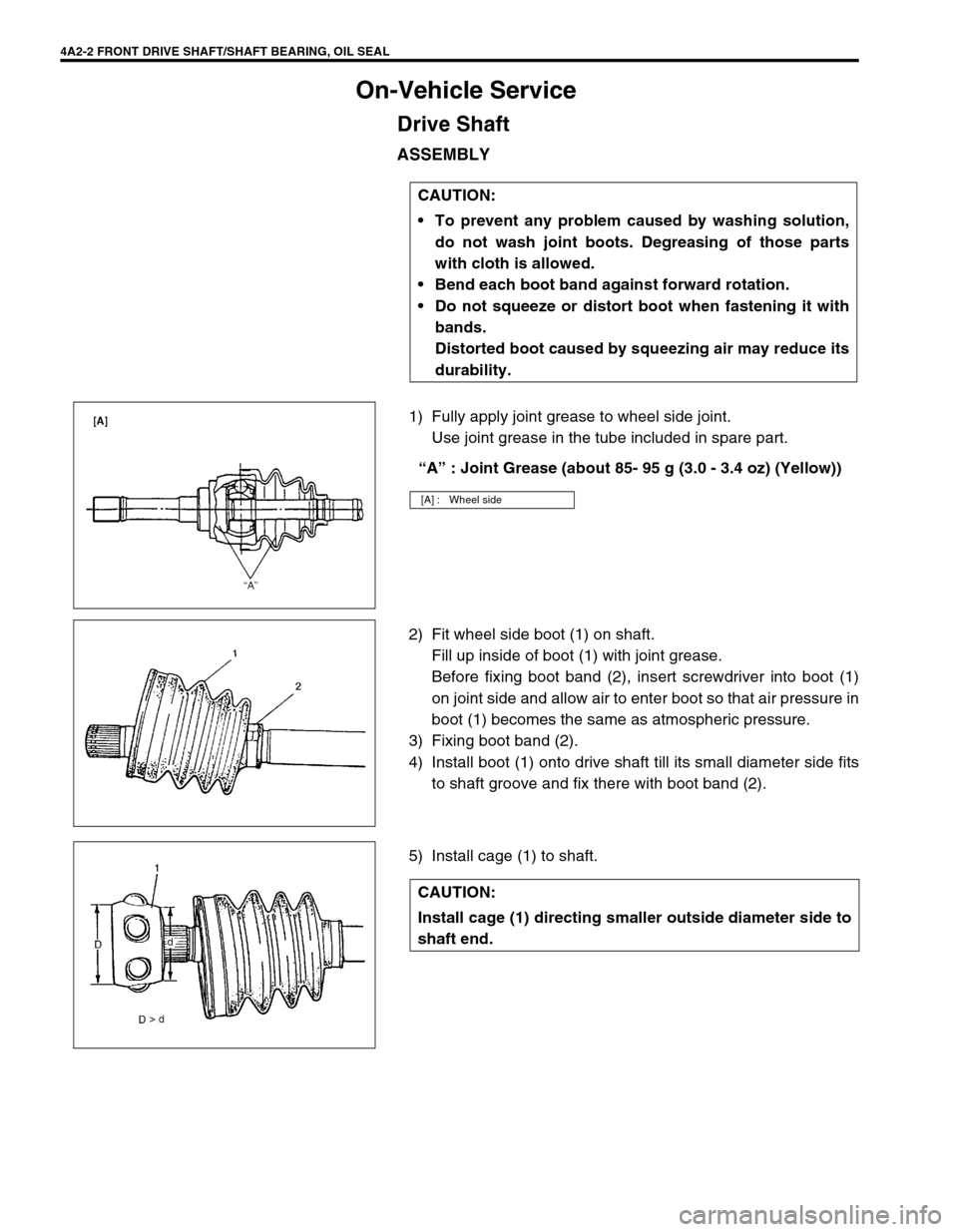
1) Fully apply joint grease to wheel side joint.
Use joint grease in the tube included in spare part.
“A” : Joint Grease (about 85- 95 g (3.0 - 3.4 oz) (Yellow))
2) Fit wheel side boot (1) on shaft.
Fill up inside of boot (1) with joint grease.
Before fixing boot band (2), insert screwdriver into boot (1)
on joint side and allow air to enter boot so that air pressure in
boot (1) becomes the same as atmospheric pressure.
3) Fixing boot band (2).
4) Install boot (1) onto drive shaft till its small diameter side fits
to shaft groove and fix there with boot band (2).
5) Install cage (1) to shaft.CAUTION:
To prevent any problem caused by washing solution,
do not wash joint boots. Degreasing of those parts
with cloth is allowed.
Bend each boot band against forward rotation.
Do not squeeze or distort boot when fastening it with
bands.
Distorted boot caused by squeezing air may reduce its
durability.
[A] : Wheel side
CAUTION:
Install cage (1) directing smaller outside diameter side to
shaft end.
Page 102 of 656
FRONT DRIVE SHAFT/SHAFT BEARING, OIL SEAL 4A2-3
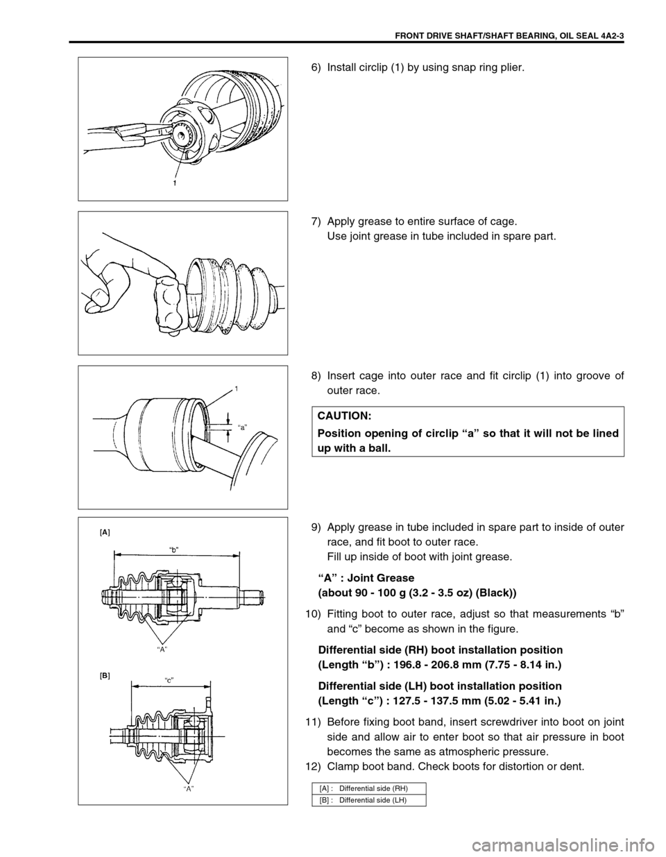
6) Install circlip (1) by using snap ring plier.
7) Apply grease to entire surface of cage.
Use joint grease in tube included in spare part.
8) Insert cage into outer race and fit circlip (1) into groove of
outer race.
9) Apply grease in tube included in spare part to inside of outer
race, and fit boot to outer race.
Fill up inside of boot with joint grease.
“A” : Joint Grease
(about 90 - 100 g (3.2 - 3.5 oz) (Black))
10) Fitting boot to outer race, adjust so that measurements “b”
and “c” become as shown in the figure.
Differential side (RH) boot installation position
(Length “b”) : 196.8 - 206.8 mm (7.75 - 8.14 in.)
Differential side (LH) boot installation position
(Length “c”) : 127.5 - 137.5 mm (5.02 - 5.41 in.)
11) Before fixing boot band, insert screwdriver into boot on joint
side and allow air to enter boot so that air pressure in boot
becomes the same as atmospheric pressure.
12) Clamp boot band. Check boots for distortion or dent.
CAUTION:
Position opening of circlip “a” so that it will not be lined
up with a ball.
[A] : Differential side (RH)
[B] : Differential side (LH)
Page 103 of 656

4A2-4 FRONT DRIVE SHAFT/SHAFT BEARING, OIL SEAL
Required Service Material
MaterialRecommended SUZUKI product
(Part Number)Use
Lithium grease SUZUKI SUPER GREASE A
(99000-25010)Drive shaft oil seal
Wheel spindle part of differential
side drive shaft (RH)
Sealant SEALING COMPOUND 366E
(99000-31090)Axle shaft drive flange
Page 123 of 656
5C-6 PARKING AND REAR BRAKE
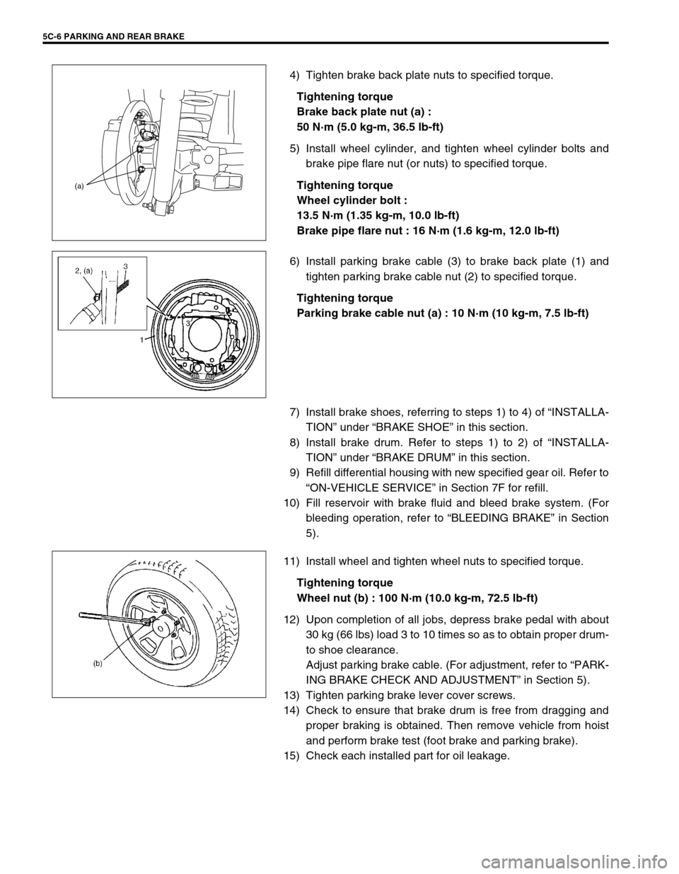
4) Tighten brake back plate nuts to specified torque.
Tightening torque
Brake back plate nut (a) :
50 N·m (5.0 kg-m, 36.5 lb-ft)
5) Install wheel cylinder, and tighten wheel cylinder bolts and
brake pipe flare nut (or nuts) to specified torque.
Tightening torque
Wheel cylinder bolt :
13.5 N·m (1.35 kg-m, 10.0 lb-ft)
Brake pipe flare nut : 16 N·m (1.6 kg-m, 12.0 lb-ft)
6) Install parking brake cable (3) to brake back plate (1) and
tighten parking brake cable nut (2) to specified torque.
Tightening torque
Parking brake cable nut (a) : 10 N·m (10 kg-m, 7.5 lb-ft)
7) Install brake shoes, referring to steps 1) to 4) of “INSTALLA-
TION” under “BRAKE SHOE” in this section.
8) Install brake drum. Refer to steps 1) to 2) of “INSTALLA-
TION” under “BRAKE DRUM” in this section.
9) Refill differential housing with new specified gear oil. Refer to
“ON-VEHICLE SERVICE” in Section 7F for refill.
10) Fill reservoir with brake fluid and bleed brake system. (For
bleeding operation, refer to “BLEEDING BRAKE” in Section
5).
11) Install wheel and tighten wheel nuts to specified torque.
Tightening torque
Wheel nut (b) : 100 N·m (10.0 kg-m, 72.5 lb-ft)
12) Upon completion of all jobs, depress brake pedal with about
30 kg (66 lbs) load 3 to 10 times so as to obtain proper drum-
to shoe clearance.
Adjust parking brake cable. (For adjustment, refer to “PARK-
ING BRAKE CHECK AND ADJUSTMENT” in Section 5).
13) Tighten parking brake lever cover screws.
14) Check to ensure that brake drum is free from dragging and
proper braking is obtained. Then remove vehicle from hoist
and perform brake test (foot brake and parking brake).
15) Check each installed part for oil leakage.
(a)
Page 164 of 656
ENGINE GENERAL INFORMATION AND DIAGNOSIS (H27 ENGINE) 6-1-3
General Information
Statement of Cleanliness and Care
An automobile engine is a combination of many machined, honed, polished and lapped surfaces with tolerances
that are measured in the thousands of an millimeter (ten thousands of inch). Accordingly, when any internal
engine parts are serviced, care and cleanliness are important. Throughout this section, it should be understood
that proper cleaning and protection of machined surfaces and friction areas is part of the repair procedure. This
is considered standard shop practice even if not specifically stated.
A liberal coating of engine oil should be applied to friction areas during assembly to protect and lubricate the
surface on initial operation.
Whenever valve train components, pistons, piston rings, connecting rods, rod bearings and crankshaft jour-
nal bearings are removed for service, they should be retained in order. At the time of installation, they should
be installed in the same locations and with the same mating surfaces as when removed.
Battery cables should be disconnected before any major work is performed on the engine. Failure to discon-
nect cables may result in damage to wire harness or other electrical parts.
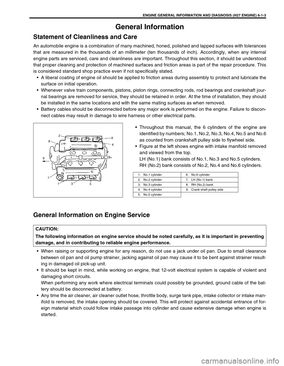
Throughout this manual, the 6 cylinders of the engine are
identified by numbers; No.1, No.2, No.3, No.4, No.5 and No.6
as counted from crankshaft pulley side to flywheel side.
Figure at the left shows engine with intake manifold removed
and viewed from the top.
LH (No.1) bank consists of No.1, No.3 and No.5 cylinders.
RH (No.2) bank consists of No.2, No.4 and No.6 cylinders.
General Information on Engine Service
When raising or supporting engine for any reason, do not use a jack under oil pan. Due to small clearance
between oil pan and oil pump strainer, jacking against oil pan may cause it to be bent against strainer result-
ing in damaged oil pick-up unit.
It should be kept in mind, while working on engine, that 12-volt electrical system is capable of violent and
damaging short circuits.
When performing any work where electrical terminals could possibly be grounded, ground cable of the bat-
tery should be disconnected at battery.
Any time the air cleaner, air cleaner outlet hose, throttle body, surge tank pipe, intake collector or intake man-
ifold is removed, the intake opening should be covered. This will protect against accidental entrance of for-
eign material which could follow intake passage into cylinder and cause extensive damage when engine is
started.
1. No.1 cylinder 6. No.6 cylinder
2. No.2 cylinder 7. LH (No.1) bank
3. No.3 cylinder 8. RH (No.2) bank
4. No.4 cylinder 9. Crank shaft pulley side
5. No.5 cylinder
CAUTION:
The following information on engine service should be noted carefully, as it is important in preventing
damage, and in contributing to reliable engine performance.
Page 174 of 656
ENGINE GENERAL INFORMATION AND DIAGNOSIS (H27 ENGINE) 6-1-13
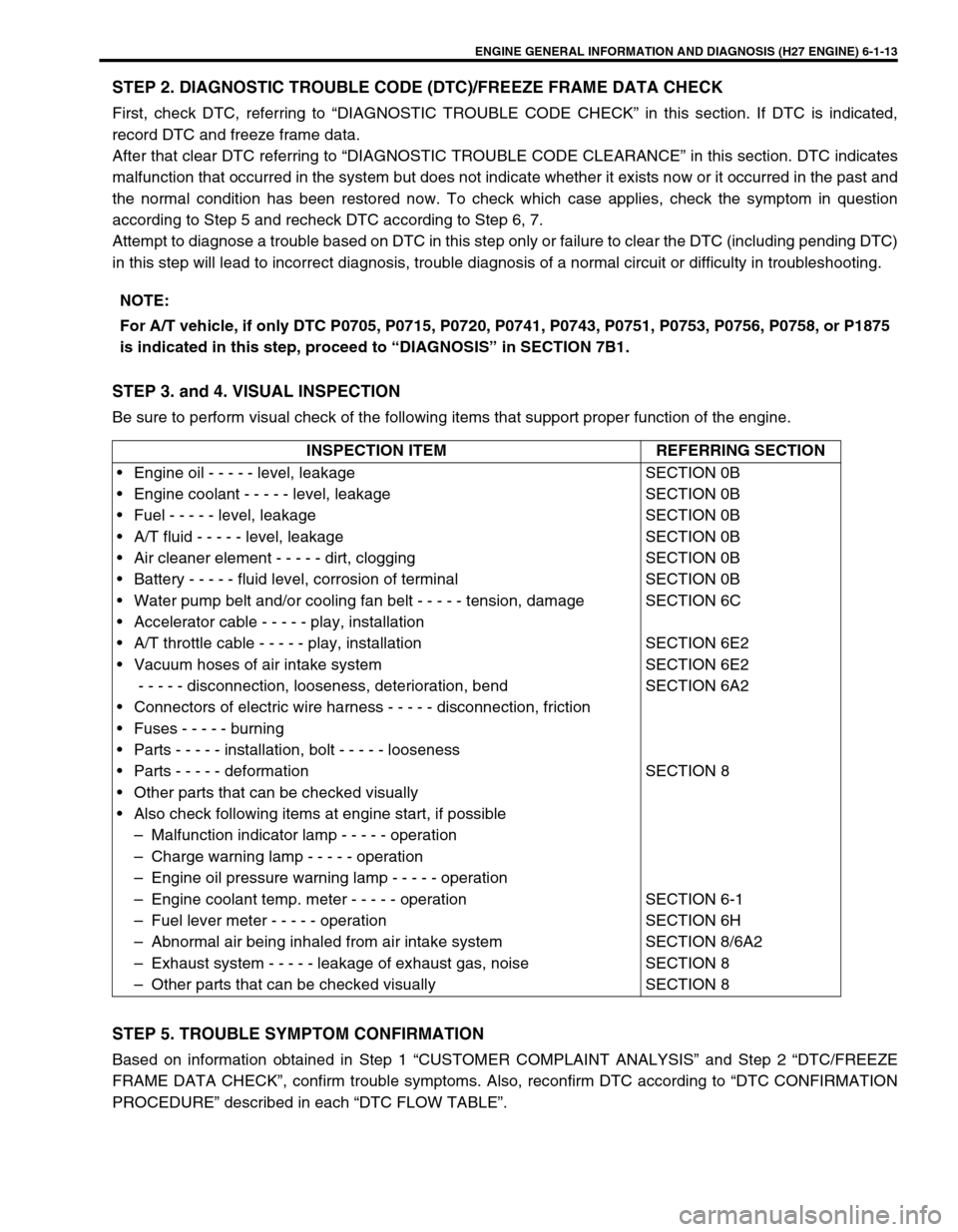
STEP 2. DIAGNOSTIC TROUBLE CODE (DTC)/FREEZE FRAME DATA CHECK
First, check DTC, referring to “DIAGNOSTIC TROUBLE CODE CHECK” in this section. If DTC is indicated,
record DTC and freeze frame data.
After that clear DTC referring to “DIAGNOSTIC TROUBLE CODE CLEARANCE” in this section. DTC indicates
malfunction that occurred in the system but does not indicate whether it exists now or it occurred in the past and
the normal condition has been restored now. To check which case applies, check the symptom in question
according to Step 5 and recheck DTC according to Step 6, 7.
Attempt to diagnose a trouble based on DTC in this step only or failure to clear the DTC (including pending DTC)
in this step will lead to incorrect diagnosis, trouble diagnosis of a normal circuit or difficulty in troubleshooting.
STEP 3. and 4. VISUAL INSPECTION
Be sure to perform visual check of the following items that support proper function of the engine.
STEP 5. TROUBLE SYMPTOM CONFIRMATION
Based on information obtained in Step 1 “CUSTOMER COMPLAINT ANALYSIS” and Step 2 “DTC/FREEZE
FRAME DATA CHECK”, confirm trouble symptoms. Also, reconfirm DTC according to “DTC CONFIRMATION
PROCEDURE” described in each “DTC FLOW TABLE”.NOTE:
For A/T vehicle, if only DTC P0705, P0715, P0720, P0741, P0743, P0751, P0753, P0756, P0758, or P1875
is indicated in this step, proceed to “DIAGNOSIS” in SECTION 7B1.
INSPECTION ITEM REFERRING SECTION
• Engine oil - - - - - level, leakage
• Engine coolant - - - - - level, leakage
• Fuel - - - - - level, leakage
• A/T fluid - - - - - level, leakage
• Air cleaner element - - - - - dirt, clogging
• Battery - - - - - fluid level, corrosion of terminal
• Water pump belt and/or cooling fan belt - - - - - tension, damage
• Accelerator cable - - - - - play, installation
• A/T throttle cable - - - - - play, installation
• Vacuum hoses of air intake system
- - - - - disconnection, looseness, deterioration, bend
• Connectors of electric wire harness - - - - - disconnection, friction
• Fuses - - - - - burning
• Parts - - - - - installation, bolt - - - - - looseness
• Parts - - - - - deformation
• Other parts that can be checked visually
• Also check following items at engine start, if possible
– Malfunction indicator lamp - - - - - operation
– Charge warning lamp - - - - - operation
– Engine oil pressure warning lamp - - - - - operation
– Engine coolant temp. meter - - - - - operation
– Fuel lever meter - - - - - operation
– Abnormal air being inhaled from air intake system
– Exhaust system - - - - - leakage of exhaust gas, noise
– Other parts that can be checked visuallySECTION 0B
SECTION 0B
SECTION 0B
SECTION 0B
SECTION 0B
SECTION 0B
SECTION 6C
SECTION 6E2
SECTION 6E2
SECTION 6A2
SECTION 8
SECTION 6-1
SECTION 6H
SECTION 8/6A2
SECTION 8
SECTION 8
Page 192 of 656

ENGINE GENERAL INFORMATION AND DIAGNOSIS (H27 ENGINE) 6-1-31
Engine Diagnosis Table
Perform troubleshooting referring to following table when ECM (PCM) has detected no DTC and no abnormality
has been found in visual inspection and engine basic inspection previously.
Condition Possible Cause Correction
Hard starting
(Engine cranks OK)Faulty idle air control system “DIAG. FLOW TABLE B-4” in this
section.
Faulty ECT sensor or MAF sensor ECT sensor or MAF sensor in Sec-
tion 6E2.
Faulty ECM (PCM) Inspection of ECM (PCM) and its
circuit in this section.
Low compression Compression check in Section
6A2.
Faulty hydraulic valve lash adjuster Valve lash adjuster in Section 6A2.
Compression leak from valve seat Valves inspection in Section 6A2.
Sticky valve stem Valves inspection in Section 6A2.
Weak or damaged valve springs Valves spring inspection in Section
6A2.
Compression leak at cylinder head gasket Cylinder head inspection in Section
6A2.
Sticking or damaged piston ring Piston ring inspection in Section
6A2.
Worn piston, ring or cylinder Cylinders, pistons and piston rings
inspection in Section 6A2.
Malfunctioning PCV valve PCV system inspection in Section
6E2.
Engine has no power
Engine overheating Refer to “OVERHEATING” in this
table.
Defective spark plug Spark plugs in Section 6F2.
Faulty ignition coil with ignitor Ignition coil in Section 6F2.
Fuel pressure out of specification
(dirty fuel filter, dirty or clogged fuel hose or
pipe, malfunctioning fuel pressure regulator,
malfunctioning fuel pump)“DIAG. FLOW TABLE B-3” in this
section.
Maladjusted TP sensor installation angle TP sensor in Section 6E2.
Faulty EGR system “DTC P0400 DIAG. FLOW TABLE”
in this section.
Faulty injector Fuel injector in Section 6E2.
Faulty TP sensor, ECT sensor or MAF sensor TP sensor, ECT sensor or MAF
sensor in Section 6E2.
Faulty ECM (PCM) Inspection of ECM (PCM) and its
circuit in this section.
Low compression Refer to the same item in “HARD
STARTING” of this table.
Dragging brakes Diagnosis in Section 5.
Slipping clutch Diagnosis in Section 7C1.