Page 89 of 656
3D-2 FRONT SUSPENSION
Tightening Torque Specification
Page 100 of 656
FRONT DRIVE SHAFT/SHAFT BEARING, OIL SEAL 4A2-1
4A2
SECTION 4A2
FRONT DRIVE SHAFT/SHAFT BEARING,
OIL SEAL
CONTENTS
On-Vehicle Service....................................... 4A2-2
Drive Shaft ................................................. 4A2-2Required Service Material ........................... 4A2-4
NOTE:
For the descriptions (items) not found in this section, refer to the same section of the Service Manual
mentioned in the FOREWORD of this manual.
Page 101 of 656
4A2-2 FRONT DRIVE SHAFT/SHAFT BEARING, OIL SEAL
On-Vehicle Service
Drive Shaft
ASSEMBLY
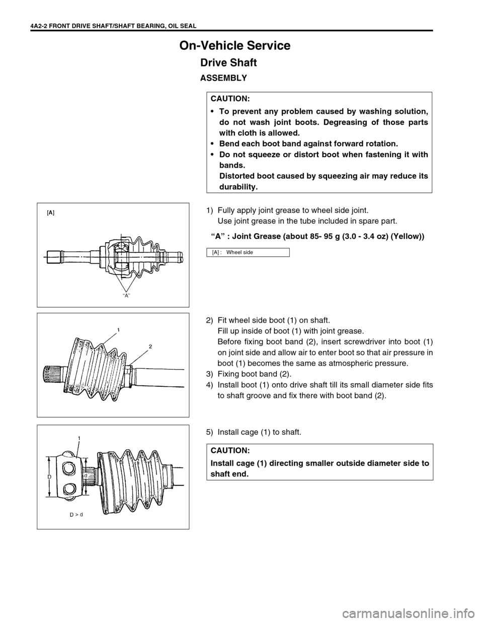
1) Fully apply joint grease to wheel side joint.
Use joint grease in the tube included in spare part.
“A” : Joint Grease (about 85- 95 g (3.0 - 3.4 oz) (Yellow))
2) Fit wheel side boot (1) on shaft.
Fill up inside of boot (1) with joint grease.
Before fixing boot band (2), insert screwdriver into boot (1)
on joint side and allow air to enter boot so that air pressure in
boot (1) becomes the same as atmospheric pressure.
3) Fixing boot band (2).
4) Install boot (1) onto drive shaft till its small diameter side fits
to shaft groove and fix there with boot band (2).
5) Install cage (1) to shaft.CAUTION:
To prevent any problem caused by washing solution,
do not wash joint boots. Degreasing of those parts
with cloth is allowed.
Bend each boot band against forward rotation.
Do not squeeze or distort boot when fastening it with
bands.
Distorted boot caused by squeezing air may reduce its
durability.
[A] : Wheel side
CAUTION:
Install cage (1) directing smaller outside diameter side to
shaft end.
Page 102 of 656
FRONT DRIVE SHAFT/SHAFT BEARING, OIL SEAL 4A2-3
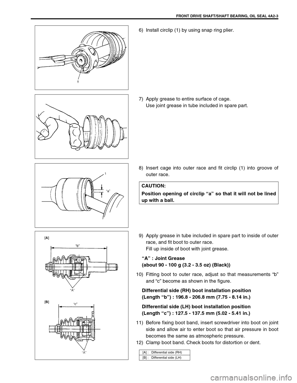
6) Install circlip (1) by using snap ring plier.
7) Apply grease to entire surface of cage.
Use joint grease in tube included in spare part.
8) Insert cage into outer race and fit circlip (1) into groove of
outer race.
9) Apply grease in tube included in spare part to inside of outer
race, and fit boot to outer race.
Fill up inside of boot with joint grease.
“A” : Joint Grease
(about 90 - 100 g (3.2 - 3.5 oz) (Black))
10) Fitting boot to outer race, adjust so that measurements “b”
and “c” become as shown in the figure.
Differential side (RH) boot installation position
(Length “b”) : 196.8 - 206.8 mm (7.75 - 8.14 in.)
Differential side (LH) boot installation position
(Length “c”) : 127.5 - 137.5 mm (5.02 - 5.41 in.)
11) Before fixing boot band, insert screwdriver into boot on joint
side and allow air to enter boot so that air pressure in boot
becomes the same as atmospheric pressure.
12) Clamp boot band. Check boots for distortion or dent.
CAUTION:
Position opening of circlip “a” so that it will not be lined
up with a ball.
[A] : Differential side (RH)
[B] : Differential side (LH)
Page 103 of 656
4A2-4 FRONT DRIVE SHAFT/SHAFT BEARING, OIL SEAL
Required Service Material
MaterialRecommended SUZUKI product
(Part Number)Use
Lithium grease SUZUKI SUPER GREASE A
(99000-25010)Drive shaft oil seal
Wheel spindle part of differential
side drive shaft (RH)
Sealant SEALING COMPOUND 366E
(99000-31090)Axle shaft drive flange
Page 104 of 656

PROPELLER SHAFTS 4B-1
4B
SECTION 4B
PROPELLER SHAFTS
CONTENTS
General Description ....................................... 4B-1
On-Vehicle Service......................................... 4B-2
Propeller Shaft ............................................. 4B-2Tightening Torque Specification .................. 4B-2
Required Service Material ............................. 4B-2
General Description
Two universal non-constant velocity joints which are called cardan joints are provided on front propeller shaft
and one universal non-constant velocity joint, two universal constant velocity joints and a rubber mounting cen-
ter support are provided on rear propeller shaft. On the front end of rear propeller shaft, cardan joint same as
that of front propeller shaft is provided. On the rear end of rear propeller shaft, ball fixed type constant velocity
joint (BJ) is provided. On the middle of rear propeller shaft, double offset type constant velocity joint (DOJ) is
provided just behind the center support.
Most universal joints require no maintenance. They are lubricated for life and can not be lubricated on the vehi-
cle. If a universal joint becomes noisy or worn, it must be replaced.
The propeller shaft is a balanced unit. Handle it carefully so that balance can be maintained.NOTE:
For the descriptions (items) not found in this section, refer to the same section of the Service Manual
mentioned in the FOREWORD of this manual.
1. Front propeller shaft
2. Rear propeller shaft
Page 105 of 656
4B-2 PROPELLER SHAFTS
On-Vehicle Service
Propeller Shaft
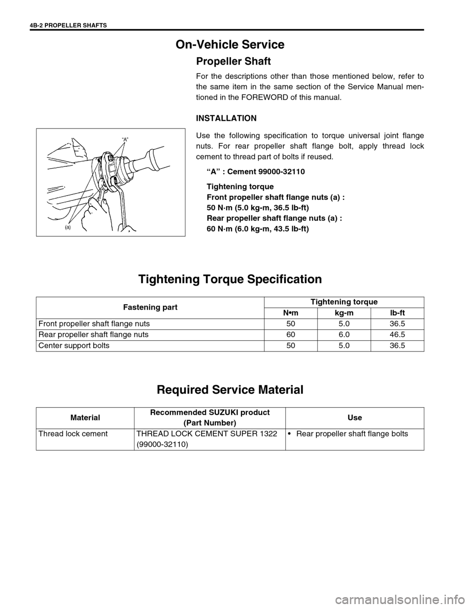
For the descriptions other than those mentioned below, refer to
the same item in the same section of the Service Manual men-
tioned in the FOREWORD of this manual.
INSTALLATION
Use the following specification to torque universal joint flange
nuts. For rear propeller shaft flange bolt, apply thread lock
cement to thread part of bolts if reused.
“A” : Cement 99000-32110
Tightening torque
Front propeller shaft flange nuts (a) :
50 N·m (5.0 kg-m, 36.5 lb-ft)
Rear propeller shaft flange nuts (a) :
60 N·m (6.0 kg-m, 43.5 lb-ft)
Tightening Torque Specification
Required Service Material
Fastening partTightening torque
Nm kg-m lb-ft
Front propeller shaft flange nuts 50 5.0 36.5
Rear propeller shaft flange nuts 60 6.0 46.5
Center support bolts 50 5.0 36.5
MaterialRecommended SUZUKI product
(Part Number)Use
Thread lock cement THREAD LOCK CEMENT SUPER 1322
(99000-32110)Rear propeller shaft flange bolts
Page 108 of 656
BRAKES PIPE/HOSE/MASTER CYLINDER 5A-1
5A
SECTION 5A
BRAKES PIPE/HOSE/MASTER CYLINDER
CONTENTS
General Description ....................................... 5A-2
Master Cylinder Assembly............................ 5A-2
On-Vehicle Service......................................... 5A-3
Front Brake Hose/Pipe ................................. 5A-3
Master Cylinder Reservoir ............................ 5A-6Master Cylinder Assembly ........................... 5A-7
Brake Booster .............................................. 5A-8
Tightening Torque Specification ................ 5A-10
Special Tool .................................................. 5A-10
WARNING:
For vehicles equipped with Supplemental Restraint (Air Bag) System:
Service on and around the air bag system components or wiring must be performed only by an
authorized SUZUKI dealer. Refer to “Air Bag System Components and Wiring Location View” under
“General Description” in air bag system section in order to confirm whether you are performing ser-
vice on or near the air bag system components or wiring. Please observe all WARNINGS and “Ser-
vice Precautions” under “On-Vehicle Service” in air bag system section before performing service
on or around the air bag system components or wiring. Failure to follow WARNINGS could result in
unintentional activation of the system or could render the system inoperative. Either of these two
conditions may result in severe injury.
Technical service work must be started at least 90 seconds after the ignition switch is turned to the
“LOCK” position and the negative cable is disconnected from the battery. Otherwise, the system
may be activated by reserve energy in the Sensing and Diagnostic Module (SDM).
NOTE:
For the descriptions (items) not found in this section, refer to the same section of the Service Man-
ual mentioned in the FOREWORD of this manual.
All brake fasteners are important attaching parts in that they could affect the performance of vital
parts and systems, and/or could result in major repair expense. They must be replaced with one of
same part number or with an equivalent part if replacement becomes necessary. Do not use a
replacement part of lesser quality or substitute design. Torque values must be used as specified
during reassembly to assure proper retention of all parts. There is to be no welding as it may result
in extensive damage and weakening of the metal.