Page 452 of 656

AUTOMATIC TRANSMISSION (4 A/T) 7B1-43
On-Vehicle Service
Maintenance Service
Fluid level
LEVEL CHECK AT NORMAL OPERATING TEMPERATURE
1) Stop vehicle and place it level.
2) Apply parking brake and place chocks against wheels.
3) With selector at P position, start engine.
4) Warm up engine till fluid temperature reaches normal oper-
ating temperature (70 – 80 °C (158 – 176 °F)). As a guide to
check fluid temperature, warm up engine till engine coolant
temperature meter indicated around 1 unit above “C” point.
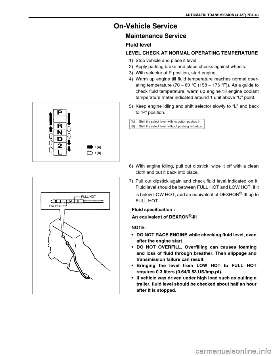
5) Keep engine idling and shift selector slowly to “L” and back
to “P” position.
6) With engine idling, pull out dipstick, wipe it off with a clean
cloth and put it back into place.
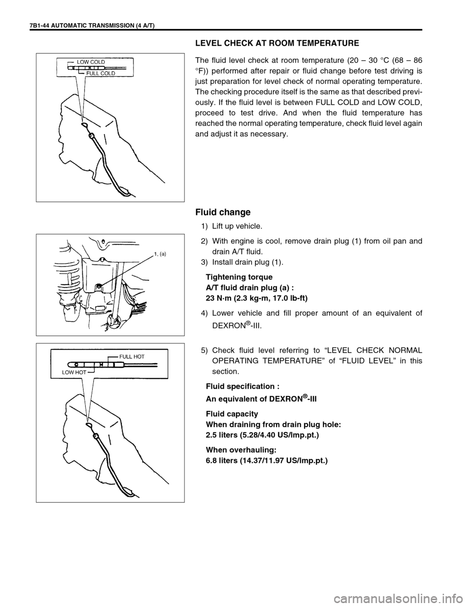
7) Pull out dipstick again and check fluid level indicated on it.
Fluid level should be between FULL HOT and LOW HOT. if it
is below LOW HOT, add an equivalent of DEXRON
®-III up to
FULL HOT.
Fluid specification :
An equivalent of DEXRON
®-III
[A] : Shift the select lever with its button pushed in.
[B] : Shift the select lever without pushing its button.
NOTE:
DO NOT RACE ENGINE while checking fluid level, even
after the engine start.
DO NOT OVERFILL. Overfilling can causes foaming
and loss of fluid through breather. Then slippage and
transmission failure can result.
Bringing the level from LOW HOT to FULL HOT
requires 0.3 liters (0.64/0.53 US/lmp.pt).
If vehicle was driven under high load such as pulling a
trailer, fluid level should be checked about half an hour
after it is stopped.
Page 453 of 656

7B1-44 AUTOMATIC TRANSMISSION (4 A/T)
LEVEL CHECK AT ROOM TEMPERATURE
The fluid level check at room temperature (20 – 30 °C (68 – 86
°F)) performed after repair or fluid change before test driving is
just preparation for level check of normal operating temperature.
The checking procedure itself is the same as that described previ-
ously. If the fluid level is between FULL COLD and LOW COLD,
proceed to test drive. And when the fluid temperature has
reached the normal operating temperature, check fluid level again
and adjust it as necessary.
Fluid change
1) Lift up vehicle.
2) With engine is cool, remove drain plug (1) from oil pan and
drain A/T fluid.
3) Install drain plug (1).
Tightening torque
A/T fluid drain plug (a) :
23 N·m (2.3 kg-m, 17.0 lb-ft)
4) Lower vehicle and fill proper amount of an equivalent of
DEXRON
®-III.
5) Check fluid level referring to “LEVEL CHECK NORMAL
OPERATING TEMPERATURE” of “FLUID LEVEL” in this
section.
Fluid specification :
An equivalent of DEXRON
®-III
Fluid capacity
When draining from drain plug hole:
2.5 liters (5.28/4.40 US/lmp.pt.)
When overhauling:
6.8 liters (14.37/11.97 US/lmp.pt.)
Page 514 of 656
![SUZUKI GRAND VITARA 1999 2.G Owners Manual INSTRUMENTATION/DRIVER INFORMATION 8C-3
COMBINATION METER INTERNAL CIRCUITS
COMBINATION METER COUPLERS
[A] : Coupler A [B] : Coupler B [C] : Coupler C
1. To Cruise control module (if equipped) GRY/YE SUZUKI GRAND VITARA 1999 2.G Owners Manual INSTRUMENTATION/DRIVER INFORMATION 8C-3
COMBINATION METER INTERNAL CIRCUITS
COMBINATION METER COUPLERS
[A] : Coupler A [B] : Coupler B [C] : Coupler C
1. To Cruise control module (if equipped) GRY/YE](/manual-img/20/7583/w960_7583-513.png)
INSTRUMENTATION/DRIVER INFORMATION 8C-3
COMBINATION METER INTERNAL CIRCUITS
COMBINATION METER COUPLERS
[A] : Coupler A [B] : Coupler B [C] : Coupler C
1. To Cruise control module (if equipped) GRY/YEL 1. To door switch (drive side) BLK/BLU 1. To ground BLK
2. Blank–2. To transmission range switch
(A/T vehicle only, if equipped) LGRN/BLU 2. To ECM (PCM for A/T vehicle) BRN
3. To ignition switch BLK/WHT 3. To transmission range switch
(A/T vehicle only, if equipped) 2GRN/ORN 3. To ignition switch PPL/RED
4. Blank–4. To transmission range switch
(A/T vehicle only, if equipped) DYEL/GRN 4. To brake fluid level switch RED/BLK
5. To ABS control module (if equipped) BLU/ORN 5. To transmission range switch
(A/T vehicle only, if equipped) NORN/BLU 5. To parking brake switch PPL
6. To PCM (A/T vehicle only) GRY/BLU 6. To transmission range switch
(A/T vehicle only, if equipped) PORN/GRN 6. To seat belt switch GRY/RED
7. To ABS control module (if equipped) BRN 7. To transmission range switch
(A/T vehicle only, if equipped) RRED 7. To generator WHT/RED
8. To VSS BLU/YEL 8. To illumination control module RED/GRN 8. To engine oil pressure switch YEL/BLK
9. To combination switch GRN/RED 9. To PCM (A/T vehicle only) WHT/BLK 9. To combination switch RED/YEL
10. To air bag SDM BLU 10. To ECT sensor YEL/WHT 10. To ignition switch BLU/RED
11. To main fuse WHT/BLU 11. To fuel level gauge BLU/WHT
12. To fuse box WHT 12. To ground BLU/YEL
13. To combination switch RED 13. To combination switch GRN/YEL
14. To immobilizer control module
(if equipped)PPL
15. To ECM (PCM for A/T vehicle) PPL/YEL
16. To ECM (PCM for A/T vehicle) ORN/BLK
P R N D 2 LCRUISEPOWER4WDSPEED
METERTACHO
METERFUEL
METERTEMP.
METER
A-11
A-13 A-8 B-12 B-11 C-8 A-15 A-6 A-1 B-9 A-16 A-14 C-7 C-1 A-10 C-3 C-4 C-5 A-7 A-5 B-8 B-1B-10 C-2 A-12 A-3B-13 B-2 B-3 B-4 B-5 B- B-6 C-9 C-10 A-9ABS circuit EBD circuit Air bag circuit
or ABS or BRAKE
if equipped
or CHECK
ENGINE
NOTE:
Terminal arrangement of coupler viewed from harness side.