1999 SUZUKI GRAND VITARA fuse
[x] Cancel search: fusePage 8 of 656

GENERAL INFORMATION 0A-3
Servicing and handling
WARNING:
Many of service procedures require disconnection of
“AIR BAG” fuse and all air bag (inflator) module(s) from
initiator circuit to avoid an accidental deployment.
Driver and Passenger Air Bag (Inflator) Modules
For handling and storage of a live air bag (inflator)
module, select a place where the ambient temperature
below 65°C (150°F), without high humidity and away
from electric noise.
When carrying a live air bag (inflator) module, make
sure the bag opening is pointed away from you. In
case of an accidental deployment, the bag will then
deploy with minimal chance of injury. Never carry the
air bag (inflator) module by the wires or connector on
the underside of the module. When placing a live air
bag (inflator) module on a bench or other surface,
always face the bag up, away from the surface. As the
live passenger air bag (inflator) module must be placed
with its bag (trim cover) facing up, place it on the work-
bench with a slit or use the workbench vise to hold it
securely at its lower mounting bracket. This is neces-
sary so that a free space is provided to allow the air
bag to expand in the unlikely event of accidental
deployment. Otherwise, personal injury may result.
Never dispose of live (undeployed) air bag (inflator)
modules (driver and passenger). If disposal is neces-
sary, be sure to deploy them according to deployment
procedures described in SECTION 10B before dis-
posal.
The air bag (inflator) module immediately after deploy-
ment is very hot. Wait for at least half an hour to cool it
off before proceeding the work.
After an air bag (inflator) module has been deployed,
the surface of the air bag may contain a powdery resi-
due. This powder consists primarily of cornstarch
(used to lubricate the bag as it inflates) and by-prod-
ucts of the chemical reaction. As with many service
procedures, gloves and safety glasses should be
worn.
[A] : ALWAYS CARRY AIR BAG (INFLATOR) MODULE WITH TRIM COVER (AIR
BAG OPENING) AWAY FROM BODY.
[B] : ALWAYS PLACE AIR BAG (INFLATOR) MODULE ON WORKBENCH WITH
TRIM COVER (AIR BAG OPENING) UP, AWAY FROM LOOSE OBJECTS.
1. Slit on workbench
2. Lower mounting bracket
3. Workbench vise
Page 31 of 656

1B-6 AIR CONDITIONING (OPTIONAL)
Diagnosis
General
Main A/C system (front A/C system)
Condition Possible Cause Correction
Cool air does not
come out (A/C system
does not operative)No refrigerant Perform recover, evacuation and
charging.
Fuse blown Check “IG METER”, “REAR DEFG”
and “A/C” fuses, and check for
short circuit to ground.
A/C switch faulty Check A/C switch.
Blower motor switch faulty Check blower motor switch.
A/C evaporator temperature sensor (A/C evap-
orator thermistor) faultyCheck A/C evaporator tempera-
ture sensor (A/C evaporator ther-
mistor).
Refrigerant (dual) pressure switch faulty Check refrigerant (dual) pressure
switch.
Wiring or grounding faulty Repair as necessary.
A/C ON permission signal in ECM faulty Check A/C ON permission signal.
A/C controller and its circuit faulty Check A/C controller and its circuit.
Cool air does not
come out (A/C com-
pressor does not
operative (won’t rota-
tive))Magnet clutch faulty Check magnet clutch.
Compressor relay faulty Check compressor thermal switch.
Compressor relay faulty Check compressor relay.
Drive belt loose or broken Adjust or replace drive belt.
Compressor faulty Check compressor.
A/C ON permission signal in ECM faulty Check A/C ON permission signal.
A/C controller faulty Check A/C controller.
Cool air does not
come out (A/C con-
denser cooling fan
motor does not opera-
tive)Condenser cooling fan motor relay faulty Check condenser cooling fan motor
relay.
Wiring or grounding faulty Repair as necessary.
A/C condenser fan motor relay signal in ECM
faultyCheck A/C condenser cooling fan
motor relay signal.
Condenser cooling fan motor faulty Check condenser cooling fan
motor.
Cool air does not
come out (Blower
motor does not opera-
tive)Fuse blown Check “FRONT BLOW” and
“REAR DEFG” fuses, and check for
short circuit to ground.
Blower motor relay faulty Check blower motor relay.
Blower motor resistor faulty Check blower motor resistor.
Blower motor switch faulty Check blower motor switch.
Wiring or grounding faulty Repair as necessary.
Blower motor faulty Check blower motor.
Page 33 of 656

1B-8 AIR CONDITIONING (OPTIONAL)
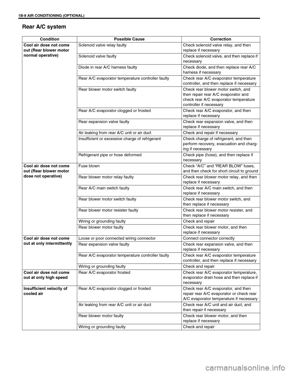
Rear A/C system
Condition Possible Cause Correction
Cool air dose not come
out (Rear blower motor
normal operative)Solenoid valve relay faulty Check solenoid valve relay, and then
replace if necessary
Solenoid valve faulty Check solenoid valve, and then replace if
necessary
Diode in rear A/C harness faulty Check diode, and then replace rear A/C
harness if necessary
Rear A/C evaporator temperature controller faulty Check rear A/C evaporator temperature
controller, and then replace if necessary
Rear blower motor switch faulty Check rear blower motor switch, and
then repair rear A/C evaporator and
check rear A/C evaporator temperature
controller if necessary
Rear A/C evaporator clogged or frosted Check rear A/C evaporator, and then
replace if necessary
Rear expansion valve faulty Check rear expansion valve, and then
replace if necessary
Air leaking from rear A/C unit or air duct Check and repair if necessary
Insufficient or excessive charge of refrigerant Check charge of refrigerant, and then
perform recovery, evacuation and charg-
ing if necessary
Refrigerant pipe or hose deformed Check pipe (hose), and then replace if
necessary
Cool air dose not come
out (Rear blower motor
dose not operative)Fuse blown Check “A/C” and “REAR BLOW” fuses,
and then check for short circuit to ground
Rear blower motor relay faulty Check rear blower motor relay, and then
replace if necessary
Rear A/C main switch faulty Check rear A/C main switch, and then
replace if necessary
Rear blower motor switch faulty Check rear blower motor switch, and
then replace if necessary
Rear blower motor resister faulty Check rear blower motor resister, and
then replace if necessary
Wiring or grounding faulty Check and repair
Rear blower motor faulty Check rear blower motor, and then
replace if necessary
Cool air dose not come
out at only intermittentlyLoose or poor connected wiring connector Connect connector correctly
Rear expansion valve faulty Check rear expansion valve, and then
replace if necessary
Rear A/C evaporator temperature controller faulty Check rear A/C evaporator temperature
controller, and then replace if necessary
Wiring or grounding faulty Check and repair
Cool air dose not come
out at only high speedRear A/C evaporator frosted Check rear A/C evaporator temperature,
evaporator drain hose and then replace if
necessary
Insufficient velocity of
cooled airRear A/C evaporator clogged or frosted Check rear A/C evaporator, and then
repair rear A/C evaporator or check rear
A/C evaporator temperature if necessary
Air leaking from rear A/C unit or air duct Check rear A/C unit and air duct, and
then repair if necessary
Rear blower motor faulty Check rear blower motor, and then
replace if necessary
Wiring or grounding faulty Check and repair
Page 39 of 656

1B-14 AIR CONDITIONING (OPTIONAL)
Wiring Circuit
ACG
LT GRN
PNK
PNK
BLKORN
BLK
YEL/GRNRED/BLKBLK/WHT
BLU/WHTPNK/BLK
PNK/GRN
RED/BLK
WHT/RED
YEL/GRN
YEL/BLU
A/C
RED/BLU
RED/BLU
RED/BLKBLK
BLU/ORN
BLU/WHT
BLU/WHT
PNK
PNK/BLU
BLK
PNK/WHT
YEL/BLK
GRY/WHT
GRN/BLK
BLK/WHT
RED/BLK
YEL/GRN
BLK
BLK
BLK
YEL/BLK
YEL/GRN
YEL/GRNBLU/GRN
BLU/YELBLUBLU/BLK
BLU/BLK
17
21
22 18
16
15
19
2026 25 24 23
14
12
29
3
4
7
33 30
31
32
28
27
1213
10
11
35 349
856
A
1. Front blower motor main relay 10. Compressor relay 19. Battery 28. Solenoid valve relay
2. Front blower motor 11. Compressor 20. Generator 29. Rear blower motor relay
3. Front blower motor resistor 12. Condenser cooling fan motor
relay21. Ignition main fuse 60 A 30. Rear blower motor resistor
4. Front blower motor switch 13. Condenser cooling fan motor 22. Heater/A/C main fuse 60 A 31. Rear blower motor
5. A/C controller 14. Fuse box 23.“IG METER” fuse 20 A 32. Rear blower motor switch
6. ECM (PCM) 15.“A/C” fuse 25 A 24.“REAR DEFG” fuse 25 A 33. Rear A/C main switch
7. Heater mode control switch 16. Ignition switch 25.“REAR BLOW” fuse 20A 34. Rear A/C evaporator temperature con-
troller
8. Dual (refrigerant) pressure switch 17. Main fuse box 26.“FRONT BLOW” fuse 30A 35. Rear A/C evaporator temperature sensor
9. A/C evaporator thermistor
(A/C evaporator temperature sensor)18. Battery main fuse 100 A 27. Solenoid valve [A] : Rear A/C wiring circuit (if equipped)
Page 41 of 656

1B-16 AIR CONDITIONING (OPTIONAL)
SYSTEM CIRCUIT
Terminal arrangement of A/C controller
Terminal arrangement of ECM
A: To “FRONT BLOW” fuse 1. Front blower motor relay 6. Dual (refrigerant) pressure switch 11. Condenser cooling fan motor
B: To “REAR DEFG” fuse 2. Front blower motor 7. A/C thermistor (evaporator temperature sensor) 12. A/C controller
C: To “IG METER” fuse 3. Front blower motor resistor 8. Compressor relay 13. ECM
D: To “A/C” fuse 4. Front blower motor switch 9. Compressor
5. A/C switch 10. Condenser cooling fan motor relay
5V
12V12V
12V5V
12V
5V
AC-A-1
AC-A-7
AC-A-4
AC-B-2
AC-B-1
AC-A-16AC-A-9
AC-A-2 AC-A-13
E61-8
E61-17
E61-22
A
DBBC
1
2
3
4
7 865
1011912
13
12 12
3
45 6 7 8 9 101112131415 16 AC-B
AC-A
87
22 23
34
3565
16 17
25
262
1
8 9
20
212
1
8 9
21
22 1 2 3 4 5 6
9
24 25 26 27 28 29 30 31 32 3310 11
12 13 14 15 16 17 18 19 20 211 2 3 4
7 8 9
10 11 12 13 14 15
18 19 20 21 22 23 243 4 5 6 7
10 11 12 13 14 15 16 17 18 19
22 23 24 25 26
27 283 4 5 6 7
10 11 12 13 14 15 16 19 18 2017
23
24 25 26 27 29 28 30 E61 C51-3 C51-1 C51-2
Page 139 of 656

5E2-14 ANTILOCK BRAKE SYSTEM (ABS)
System Circuit
1. Battery 11. ABS fail-safe transistor (Solenoid valve transistor) 21. To ECM and SDM (if equipped)
2. Main fuses 12. ABS pump motor transistor 22. Stop lamp
3. Ignition switch 13. Pump motor 23. Stop lamp switch
4. Circuit fuses 14. Solenoid valves 24. G sensor (For 4WD vehicle only)
5. Combination meter 15. Diagnosis monitor coupler 25. 4WD lamp (For 4WD vehicle only)
6. ABS warning lamp 16. Right-rear wheel speed sensor 26. ECM (PCM) (For 4WD vehicle only)
7. Brake warning lamp (“EBD” warning lamp) 17. Left-rear wheel speed sensor 27. 4WD switch (For 4WD vehicle only)
8. Warning lamp driver module (for ABS) 18. Right-front wheel speed sensor 28. ECM (PCM)
9. ABS hydraulic unit/control module assembly 19. Left-front wheel speed sensor
10. Terminal arrangement of connector E136 for
ABS hydraulic unit/control module assembly20. Data link connector
TERMINAL CIRCUIT TERMINAL CIRCUIT
E1361 Idle up signal
E13614 ABS warning lamp
2 Stop lamp switch 15 Left-front wheel speed sensor (+)
3 Right-front wheel speed sensor (+) 16 Left-front wheel speed sensor (–)
4 Right-front wheel speed sensor (–) 17 4WD switch
5–18 Ignition switch
6 Right-rear wheel speed sensor (–) 19 Left-rear wheel speed sensor (+)
7 Right-rear wheel speed sensor (+) 20 Left-rear wheel speed sensor (–)
8–21 Data link connector
9–22 Ground (for ABS pump motor)
10 Brake warning lamp (EBD warning lamp) 23 ABS pump motor relay
11 G sensor (For 4WD vehicle only) 24 Ground (for ABS control module)
12 Diagnosis switch terminal 25 ABS fail-safe relay
13 Ground (For G sensor) (For 4WD vehicle only)
Page 140 of 656

ANTILOCK BRAKE SYSTEM (ABS) 5E2-15
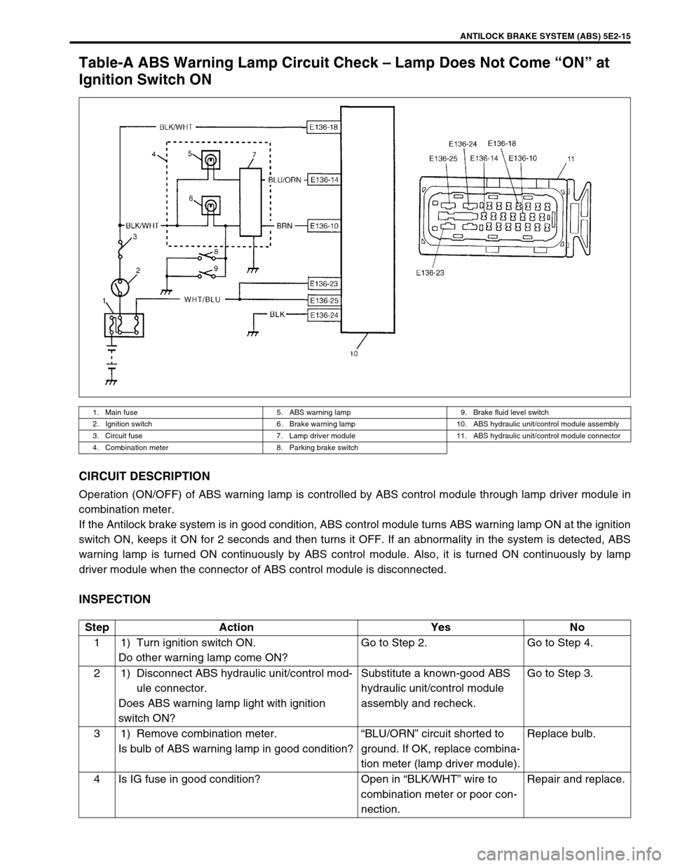
Table-A ABS Warning Lamp Circuit Check – Lamp Does Not Come “ON” at
Ignition Switch ON
CIRCUIT DESCRIPTION
Operation (ON/OFF) of ABS warning lamp is controlled by ABS control module through lamp driver module in
combination meter.
If the Antilock brake system is in good condition, ABS control module turns ABS warning lamp ON at the ignition
switch ON, keeps it ON for 2 seconds and then turns it OFF. If an abnormality in the system is detected, ABS
warning lamp is turned ON continuously by ABS control module. Also, it is turned ON continuously by lamp
driver module when the connector of ABS control module is disconnected.
INSPECTION
1. Main fuse 5. ABS warning lamp 9. Brake fluid level switch
2. Ignition switch 6. Brake warning lamp 10. ABS hydraulic unit/control module assembly
3. Circuit fuse 7. Lamp driver module 11. ABS hydraulic unit/control module connector
4. Combination meter 8. Parking brake switch
Step Action Yes No
1 1) Turn ignition switch ON.
Do other warning lamp come ON?Go to Step 2. Go to Step 4.
2 1) Disconnect ABS hydraulic unit/control mod-
ule connector.
Does ABS warning lamp light with ignition
switch ON?Substitute a known-good ABS
hydraulic unit/control module
assembly and recheck.Go to Step 3.
3 1) Remove combination meter.
Is bulb of ABS warning lamp in good condition?“BLU/ORN” circuit shorted to
ground. If OK, replace combina-
tion meter (lamp driver module).Replace bulb.
4 Is IG fuse in good condition? Open in “BLK/WHT” wire to
combination meter or poor con-
nection.Repair and replace.
Page 150 of 656

ANTILOCK BRAKE SYSTEM (ABS) 5E2-25
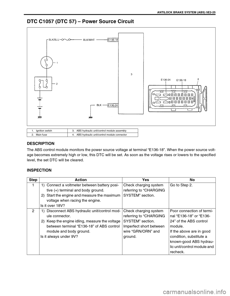
DTC C1057 (DTC 57) – Power Source Circuit
DESCRIPTION
The ABS control module monitors the power source voltage at terminal “E136-18”. When the power source volt-
age becomes extremely high or low, this DTC will be set. As soon as the voltage rises or lowers to the specified
level, the set DTC will be cleared.
INSPECTION
1. Ignition switch 3. ABS hydraulic unit/control module assembly
2. Main fuse 4. ABS hydraulic unit/control module connector
Step Action Yes No
1 1) Connect a voltmeter between battery posi-
tive (+) terminal and body ground.
2) Start the engine and measure the maximum
voltage when racing the engine.
Is it over 18V?Check charging system
referring to “CHARGING
SYSTEM” section.Go to Step 2.
2 1) Disconnect ABS hydraulic unit/control mod-
ule connector.
2) Keep the engine idling, measure the voltage
between terminal “E136-18” of ABS control
module and body ground.
Is it always under 9V?Check charging system
referring to “CHARGING
SYSTEM” section.
Imperfect short between
wire “GRN/ORN” and
ground.Poor connection of termi-
nal “E136-18” or “E136-
24” of the ABS control
module.
If the above are in good
condition, substitute a
known-good ABS hydrau-
lic unit/control module and
recheck.