1999 SUZUKI GRAND VITARA Crankshaft
[x] Cancel search: CrankshaftPage 18 of 656

MAINTENANCE AND LUBRICATION 0B-5
Maintenance Service
Engine and Emission Control
ITEM 1-1
Drive belt inspection and replacement
WATER PUMP AND GENERATOR DRIVE BELT INSPEC-
TION
1) Disconnect negative (–) cable at battery.
2) Inspect belt for cracks, cuts, deformation, wear and cleanli-
ness. If any defect exists, replace.
Check belt for tension.
Water pump and generator belt tension “a”: 9-11 mm
(0.35- 0.43 in.) deflection under 100 N, 10 kg or 22 lb pres-
sure
3) If belt is too tight or too loose, adjust it to specification by
adjusting alternator position.
4) Tighten alternator adjusting bolt and pivot bolts.
5) Connect negative (–) cable to battery.
WATER PUMP AND GENERATOR DRIVE BELT REPLACE-
MENT
Replace belt. Refer to Section 6B for replacement procedure of
pump belt.WARNING:
All inspection and replacement are to be performed with
ENGINE NOT RUNNING.
NOTE:
When replacing belt with a new one, adjust belt tension
to 7 - 9 mm (0.28 - 0.35 in.)
1. Crankshaft pulley
2. Water pump pulley
3. 100 N, 10 kg or 22 lb
Page 19 of 656

0B-6 MAINTENANCE AND LUBRICATION
POWER STEERING PUMP AND/OR A/C COMPRESSOR
DRIVE BELTS (IF EQUIPPED) INSPECTION
1) Disconnect negative (–) cable at battery.
2) Inspect belt for cracks, cuts, deformation, wear and cleanli-
ness. If any defect exists, replace.
Check belt for tension.
If belt tension is out of above specification, adjust it referring
to Section 1B or 3B1.
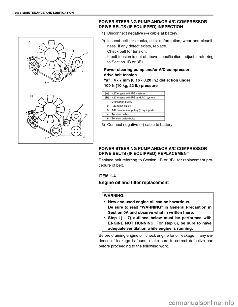
Power steering pump and/or A/C compressor
drive belt tension
“a” : 4 - 7 mm (0.16 - 0.28 in.) deflection under
100 N (10 kg, 22 lb) pressure
3) Connect negative (–) cable to battery.
POWER STEERING PUMP AND/OR A/C COMPRESSOR
DRIVE BELTS (IF EQUIPPED) REPLACEMENT
Replace belt referring to Section 1B or 3B1 for replacement pro-
cedure of belt.
ITEM 1-4
Engine oil and filter replacement
Before draining engine oil, check engine for oil leakage. If any evi-
dence of leakage is found, make sure to correct defective part
before proceeding to the following work.
[A]: H27 engine with P/S system
[B]: H27 engine with P/S and A/C system
1. Crankshaft pulley
2. P/S pump pulley
3. A/C compressor pulley (if equipped)
4. Tension pulley
5. Tension pulley bolts
WARNING:
New and used engine oil can be hazardous.
Be sure to read “WARNING” in General Precaution in
Section 0A and observe what in written there.
Step 1) - 7) outlined below must be performed with
ENGINE NOT RUNNING. For step 8), be sure to have
adequate ventilation while engine is running.
Page 73 of 656

3B1-2 POWER STEERING (P/S) SYSTEM
General Description
Power Steering (P/S) Pump
Power steering (P/S) pump specification :
The specification of this power steering pump is the same as the specification of the same section in the service
manual mentioned in this manual except for data of relieved pressure shown below.
Relieved pressure :
7850 kPa (78.5 kg/cm
2, 1116 psi)
Diagnosis
Power Steering Pump Drive Belt
Belt inspection
Check P/S pump drive belt (1) is free from any damage and prop-
erly fitted in pulley groove.
Belt tension check
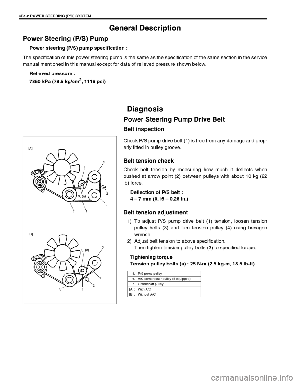
Check belt tension by measuring how much it deflects when
pushed at arrow point (2) between pulleys with about 10 kg (22
lb) force.
Deflection of P/S belt :
4 – 7 mm (0.16 – 0.28 in.)
Belt tension adjustment
1) To adjust P/S pump drive belt (1) tension, loosen tension
pulley bolts (3) and turn tension pulley (4) using hexagon
wrench.
2) Adjust belt tension to above specification.
Then tighten tension pulley bolts (3) to specified torque.
Tightening torque
Tension pulley bolts (a) : 25 N·m (2.5 kg-m, 18.5 lb-ft)
5. P/S pump pulley
6. A/C compressor pulley (if equipped)
7. Crankshaft pulley
[A] : With A/C
[B] : Without A/C
Page 163 of 656

6-1-2 ENGINE GENERAL INFORMATION AND DIAGNOSIS (H27 ENGINE)
Table A-4 Malfunction Indicator Lamp
Check – MIL Does Not Flash or Just
Remains ON Even with Grounding
Diagnosis Switch Terminal (Vehicle with
Monitor Connector) ................................... 6-1-45
Table A-5 ECM (PCM) Power and Ground
Circuit Check – MIL Doesn’t Light at
Ignition Switch ON and Engine Doesn’t
Start Though It Is Cranked Up .................. 6-1-46
DTC P0100 (DTC No.33, 34) Mass Air
Flow Circuit Malfunction ............................ 6-1-48
DTC P0110 (DTC No.23, 25) Intake Air
Temp. (IAT) Circuit Malfunction ................ 6-1-50
DTC P0115 (DTC No.14, 15) Engine
Coolant Temp. Circuit Malfunction ............ 6-1-52
DTC P0120 (DTC No.21, 22) Throttle
Position Circuit Malfunction....................... 6-1-54
DTC P0121 Throttle Position Circuit
Range/Performance Problem ................... 6-1-56
DTC P0130 (DTC No.13) HO2S-1 (Bank 1)
Circuit Malfunction or No Activity
Detected.................................................... 6-1-58
DTC P0133 HO2S-1 (Bank 1) Circuit Slow
Response .................................................. 6-1-60
DTC P0135 HO2S-1 (Bank 1) Heater
Circuit Malfunction .................................... 6-1-61
DTC P0136 HO2S-2 (Bank 1) Circuit
Malfunction................................................ 6-1-63
DTC P0141 HO2S-2 (Bank 1) Heater
Circuit Malfunction .................................... 6-1-65
DTC P0150 (DTC No.26) HO2S-1 (Bank 2)
Circuit Malfunction or No Activity
Detected.................................................... 6-1-67
DTC P0153 HO2S-1 (Bank 2) Circuit Slow
Response .................................................. 6-1-69
DTC P0155 HO2S-1 (Bank 2) Heater
Circuit Malfunction .................................... 6-1-70
DTC P0156 HO2S-2 (Bank 2) Circuit
Malfunction................................................ 6-1-72
DTC P0161 HO2S-2 (Bank 2) Heater
Circuit Malfunction .................................... 6-1-74
DTC P0171/P0172 Fuel System Too
Lean/Rich (Bank 1) ................................... 6-1-76
DTC P0174/P0175 Fuel System Too
Lean/Rich (Bank 2) ................................... 6-1-78
DTC P0300/P0301/P0302/P0303/P0304/
P0305/P0306 Random Misfire/Cylinder 1
Misfire/Cylinder 2 Misfire/Cylinder 3 Misfire/
Cylinder 4 Misfire Detected/Cylinder 5
Misfire Detected/Cylinder 6 Misfire
Detected.................................................... 6-1-80
DTC P0325 (DTC No.43) Knock Sensor Circuit Malfunction ..................................... 6-1-82
DTC P0335 Crankshaft Position Sensor
Circuit Malfunction ..................................... 6-1-84
DTC P0340 (DTC No.42) Camshaft
Position Sensor Circuit Malfunction ........... 6-1-86
DTC P0400 Exhaust Gas Recirculation
Flow Malfunction ........................................ 6-1-89
DTC P0403 (DTC No.51) Exhaust Gas
Recirculation Circuit Malfunction ............... 6-1-92
DTC P0420 Catalyst System Efficiency
Below Threshold (Bank 1) ......................... 6-1-94
DTC P0430 Catalyst System Efficiency
Below Threshold (Bank 2) ......................... 6-1-96
DTC P0443 Evap Control System Purge
Control Valve Circuit Malfunction............... 6-1-98
Evap canister purge system
inspection ............................................. 6-1-100
Vacuum passage inspection ................ 6-1-100
Vacuum hose inspection ...................... 6-1-101
Evap canister purge valve and its
circuit inspection .................................. 6-1-101
Evap canister purge valve inspection .. 6-1-101
DTC P0460 Fuel Level Sensor Circuit
High Input ................................................ 6-1-103
DTC P0500 (DTC No.24) Vehicle Speed
Sensor Malfunction .................................. 6-1-105
DTC P0505 Idle Air Control System
Malfunction .............................................. 6-1-108
DTC P0601 (DTC No.71) Internal Control
Module Memory Check Sum Error .......... 6-1-110
DTC P1408 Manifold Absolute Pressure
Sensor Circuit Malfunction ....................... 6-1-111
DTC P1450/P1451 Barometric Pressure
Sensor Circuit Malfunction/Performance
Problem ................................................... 6-1-113
DTC P1500 Engine Starter Signal Circuit
Malfunction .............................................. 6-1-114
DTC P1510 Ecm Back-Up Power Supply
Malfunction .............................................. 6-1-115
Table B-1 Fuel Pump Circuit Inspection .. 6-1-116
Table B-2 Fuel Injectors and Circuit
Inspection ................................................ 6-1-117
Table B-3 Fuel Pressure Inspection ........ 6-1-119
Table B-4 Idle Air Control System
Inspection ................................................ 6-1-121
Table B-5 A/C Signal Circuits Inspection
(If Equipped) ............................................ 6-1-123
Table B-6 A/C Condenser Fan Motor
Relay Control System Inspection
(If Equipped) ............................................ 6-1-124
Special Tool ............................................... 6-1-125
Page 164 of 656

ENGINE GENERAL INFORMATION AND DIAGNOSIS (H27 ENGINE) 6-1-3
General Information
Statement of Cleanliness and Care
An automobile engine is a combination of many machined, honed, polished and lapped surfaces with tolerances
that are measured in the thousands of an millimeter (ten thousands of inch). Accordingly, when any internal
engine parts are serviced, care and cleanliness are important. Throughout this section, it should be understood
that proper cleaning and protection of machined surfaces and friction areas is part of the repair procedure. This
is considered standard shop practice even if not specifically stated.
A liberal coating of engine oil should be applied to friction areas during assembly to protect and lubricate the
surface on initial operation.
Whenever valve train components, pistons, piston rings, connecting rods, rod bearings and crankshaft jour-
nal bearings are removed for service, they should be retained in order. At the time of installation, they should
be installed in the same locations and with the same mating surfaces as when removed.
Battery cables should be disconnected before any major work is performed on the engine. Failure to discon-
nect cables may result in damage to wire harness or other electrical parts.
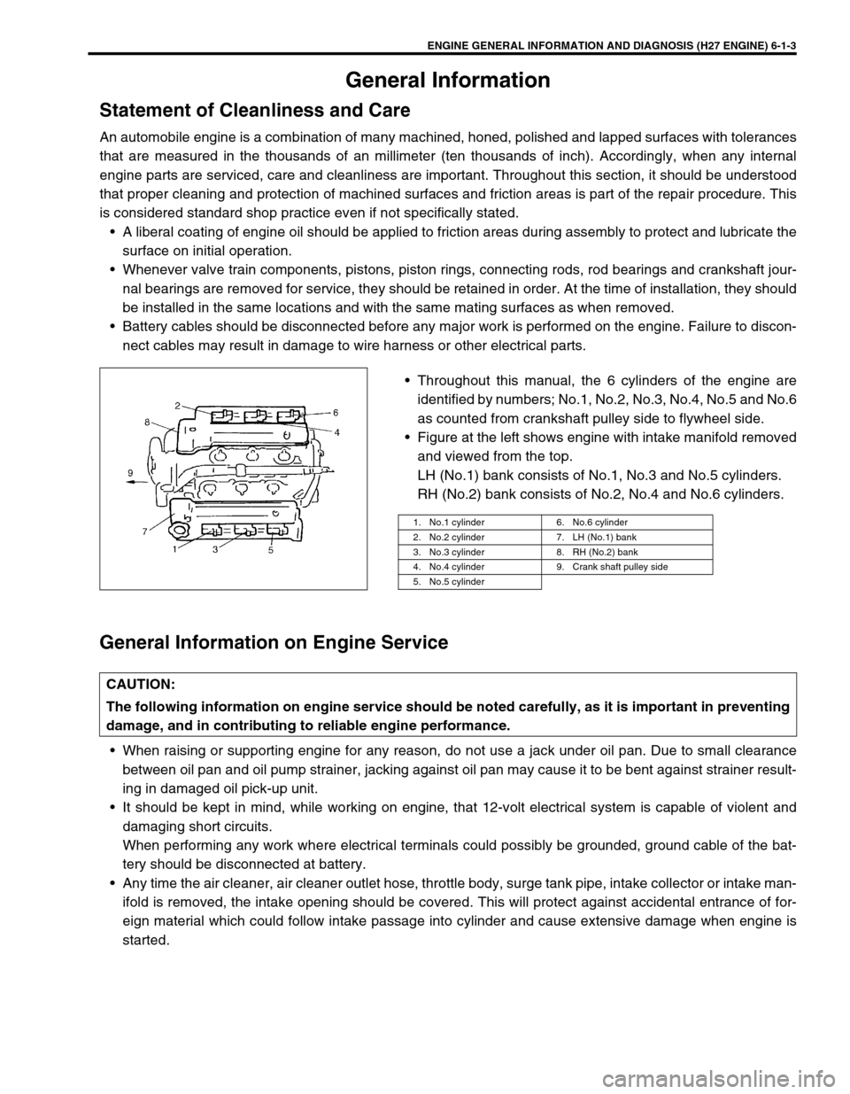
Throughout this manual, the 6 cylinders of the engine are
identified by numbers; No.1, No.2, No.3, No.4, No.5 and No.6
as counted from crankshaft pulley side to flywheel side.
Figure at the left shows engine with intake manifold removed
and viewed from the top.
LH (No.1) bank consists of No.1, No.3 and No.5 cylinders.
RH (No.2) bank consists of No.2, No.4 and No.6 cylinders.
General Information on Engine Service
When raising or supporting engine for any reason, do not use a jack under oil pan. Due to small clearance
between oil pan and oil pump strainer, jacking against oil pan may cause it to be bent against strainer result-
ing in damaged oil pick-up unit.
It should be kept in mind, while working on engine, that 12-volt electrical system is capable of violent and
damaging short circuits.
When performing any work where electrical terminals could possibly be grounded, ground cable of the bat-
tery should be disconnected at battery.
Any time the air cleaner, air cleaner outlet hose, throttle body, surge tank pipe, intake collector or intake man-
ifold is removed, the intake opening should be covered. This will protect against accidental entrance of for-
eign material which could follow intake passage into cylinder and cause extensive damage when engine is
started.
1. No.1 cylinder 6. No.6 cylinder
2. No.2 cylinder 7. LH (No.1) bank
3. No.3 cylinder 8. RH (No.2) bank
4. No.4 cylinder 9. Crank shaft pulley side
5. No.5 cylinder
CAUTION:
The following information on engine service should be noted carefully, as it is important in preventing
damage, and in contributing to reliable engine performance.
Page 181 of 656

6-1-20 ENGINE GENERAL INFORMATION AND DIAGNOSIS (H27 ENGINE)
P0174 Fuel system too lean (Bank 2)Short term fuel trim or total fuel trim
(short and long terms added) is larger
than specification for specified time or
longer. (Fuel trim toward rich side is
large.)2 driving
cyclesNot
applicable
P0175 Fuel system too rich (Bank 2)Short term fuel trim or total fuel trim
(short and long terms added) is
smaller than specification for specified
time or longer. (Fuel trim toward lean
side is large.)2 driving
cyclesNot
applicable
P0300
P0301
P0302
P0303
P0304
P0305
P0306Random misfire detected
Cylinder 1 misfire detected
Cylinder 2 misfire detected
Cylinder 3 misfire detected
Cylinder 4 misfire detected
Cylinder 5 misfire detected
Cylinder 6 misfire detectedMisfire of such level as to cause dam-
age to three way catalystMIL flashing
during mis-
fire detec-
tionNot
applicable
Misfire of such level as to deteriorate
emission but not to cause damage to
three way catalyst2 driving
cyclesNot
applicable
P0325
(No.43)Knock sensor circuit malfunc-
tionSensor output too low
1 driving
cycle1 driving
cycle
Sensor output too high
P0335Crankshaft position sensor cir-
cuit malfunctionNo signal during engine running and
CMP sensor signal inputting1 driving
cycleNot
applicable
P0340
(No.42)Camshaft position sensor cir-
cuit malfunctionNo signal for 3 sec. during engine
cranking, REF signal pattern incor-
rect or POS signal voltage too high or
too low1 driving
cycleNot
applicable
P0400Exhaust gas recirculation flow
malfunction detectedExcessive or insufficient EGR flow.2 driving
cyclesNot
applicable
P0403
(No.51)EGR valve circuit malfunctionEGR valve electrical circuit open or
shot to ground1 driving
cycle1 driving
cycle
P0420Catalyst system efficiency
below threshold (Bank 1)Output waveforms of HO2S-1 and
HO2S-2 are similar.
(Time from output voltage change of
HO2S-1 to that of HO2S-2 is shorter
than specification.)2 driving
cyclesNot
applicable
P0430Catalyst system efficiency
below threshold (Bank 2)Output waveforms of HO2S-1 and
HO2S-2 are similar.
(Time from output voltage change of
HO2S-1 to that of HO2S-2 is shorter
than specification.)2 driving
cyclesNot
applicable
P0443Purge control valve circuit
malfunctionPurge control valve circuit is open or
shorted to ground.2 driving
cyclesNot
applicable
P0500
(No.24)Vehicle speed sensor mal-
functionNo signal while running in “D” range
or during fuel cut at decelerating.2 driving
cycles1 driving
cycle DTC NO. DETECTED ITEMDETECTING CONDITION
(DTC will set when detecting : )MIL
(vehicle
without
monitor
connector)MIL
(vehicle
with
monitor
connector)
Page 196 of 656

ENGINE GENERAL INFORMATION AND DIAGNOSIS (H27 ENGINE) 6-1-35
Engine noise
(Note : Before check-
ing the mechanical
noise, make sure the
followings : Ignition
timing is properly
adjusted, Specified
spark plug is used,
Specified fuel is used.)Faulty hydraulic valve lash adjuster Hydraulic valve lash adjuster in
Section 6A2.
Worn valve stem and guide Valves inspection in Section 6A2.
Weak or broken valve spring Valve springs inspection in Section
6A2.
Warped or bent valve Valves inspection in Section 6A2.
Loose camshaft housing bolts Camshafts in Section 6A2.
Worn piston, ring and cylinder bore Pistons and cylinders inspection in
Section 6A2.
Worn crankpin bearing Crankpin and connecting rod bear-
ing inspection in Section 6A2.
Worn crankpin Crankpin and connecting rod bear-
ing inspection in Section 6A2.
Loose connecting rod nuts Connecting rod installation in Sec-
tion 6A2.
Low oil pressure Refer to “LOW OIL PRESSURE” of
this table.
Worn crankshaft journal bearing Crankshaft and bearing inspection
in Section 6A2.
Worn crankshaft journal Crankshaft and bearing inspection
in Section 6A2.
Loose lower crankcase (bearing cap) bolts Crankshaft installation in Section
6A2.
Excessive crankshaft thrust play Crankshaft inspection in Section
6A2. Condition Possible Cause Correction
Page 201 of 656

6-1-40 ENGINE GENERAL INFORMATION AND DIAGNOSIS (H27 ENGINE)
C51-1-10A/T input speed sensor (–)
(A/T vehicle)About 2.5 V Ignition switch ON
C51-1-11A/T input speed sensor (+)
(A/T vehicle)About 2.5 V Ignition switch ON
C51-1-12 Camshaft position sensor 1Deflects between
0 – 1 V and 4 – 6 VIgnition switch ON, crankshaft
turned slowly
C51-1-13 Camshaft position sensor 2Deflects between
0 – 1 V and 4 – 6 VIgnition switch ON, crankshaft
turned slowly
C51-1-14 Vehicle speed sensorDeflects between
0 – 1 V and over 4VIgnition switch ON, Rear right tire
turned slowly with rear left tire
locked
C51-1-15 EVAP canister purge valve 10 – 14 V Ignition switch ON
C51-1-16 IAC valve (stepper motor coil 4) – –
C51-1-17 IAC valve (stepper motor coil 3) – –
C51-1-18Transmission range switch “D”
(A/T vehicle)10 – 14 VIgnition switch ON, selector lever :
“D” range
0 – 1 VIgnition switch ON, selector lever :
Other than “D” range
C51-1-19Transmission range switch “N”
(A/T vehicle)10 – 14 VIgnition switch ON, selector lever :
“N” range
0 – 1 VIgnition switch ON, selector lever :
Other than “N” range
C51-1-20Shield wire ground for A/T output
speed sensor (A/T vehicle)––
C51-1-21Shield wire ground for A/T input
speed sensor (A/T vehicle)––
C51-1-22A/T output speed sensor (–)
(A/T vehicle)About 2.5 V Ignition switch ON
C51-1-23A/T output speed sensor (+)
(A/T vehicle)About 2.5 V Ignition switch ON
C51-1-24 Engine start signal10 – 14 V While engine cranking
0 – 1 V Other than above
C51-1-25 Power steering pressure switch10 – 14 V Ignition switch ON
0 – 1 VWith engine running at idle speed,
turning steering wheel to the right or
left as far as it stops
C51-1-26 4WD low switch0 – 1 VIgnition switch ON, Transfer lever :
4WD low range
10 – 14 VIgnition switch ON, Transfer lever :
4H or 2H range
C51-1-27Transmission range switch “L”
(A/T vehicle)10 – 14 VIgnition switch ON, selector lever :
“L” range
0 – 1 VIgnition switch ON, selector lever :
Other than “L” range
C51-1-28Transmission range switch “2”
(A/T vehicle)10 – 14 VIgnition switch ON, selector lever :
“2” range
0 – 1 VIgnition switch ON, selector lever :
Other than “2” range TERMINAL CIRCUIT NORMAL VOLTAGE CONDITION