1999 SUZUKI BALENO heater
[x] Cancel search: heaterPage 18 of 65

60G-74E
INSTRUMENT PANEL
INSTRUMENT PANEL
Instrument Panel 5-1
Instrument Cluster 5-2
Warning and Indicator Lights 5-3
Speedometer/Odometer/Tripmeter (if equipped) 5-5
Tachometer (if equipped) 5-6
Fuel Gauge 5-6
Temperature Gauge 5-6
Hazard Warning Switch 5-7
Rear Window Defroster Switch (if equipped) 5-7
Cigarette Lighter (if equipped) 5-7
Ashtray 5-8
Glove Box 5-8
Heating System (if equipped) 5-9
System Operating Instructions 5-10
Air Conditioning System (if equipped) 5-13
System Operating Instructions 5-13
37
INSTRUMENT PANEL
60G-74E
INSTRUMENT PANEL
1. Instrument cluster
2. Ignition switch
3. Lighting switch/Turn signal and
dimmer switch
4. Windscreen wiper and washer
switch
5. Hazard warning switch
6. Rear window defroster switch
(if equipped)
7. Other switches (if equipped)
8. Heater control panel
9. Audio system (if equipped)
10. Cigarette lighter (if equipped)
11. Ashtray
12. Bonnet release
13. Center ventilator
14. Side ventilator
15. Side defroster
16. Glove box
17. Fuse box
18. Cup holder (if equipped)
5-1
38
Page 25 of 65

60G-74E
INSTRUMENT PANEL
60G-05-024
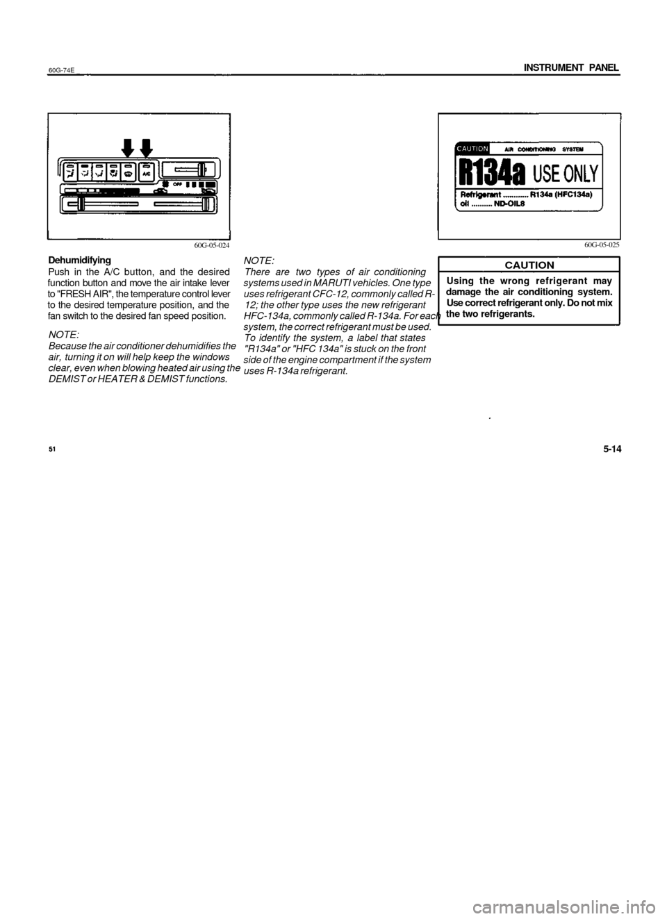
Dehumidifying
Push in the A/C button, and the desired
function button and move the air intake lever
to "FRESH AIR", the temperature control lever
to the desired temperature position, and the
fan switch to the desired fan speed position.
NOTE:
Because the air conditioner dehumidifies the
air, turning it on will help keep the windows
clear, even when blowing heated air using the
DEMIST or HEATER & DEMIST functions.
60G-05-025
NOTE:
There are two types of air conditioning
systems used in MARUTI vehicles. One type
uses refrigerant CFC-12, commonly called R-
12; the other type uses the new refrigerant
HFC-134a, commonly called R-134a. For each
system, the correct refrigerant must be used.
To identify the system, a label that states
"R134a" or "HFC 134a" is stuck on the front
side of the engine compartment if the system
uses R-134a refrigerant.
CAUTION
Using the wrong refrigerant may
damage the air conditioning system.
Use correct refrigerant only. Do not mix
the two refrigerants.
60G-74E
5-14
OTHER CONTROLS AND EQUIPMENT
OTHER CONTROLS AND EQUIPMENT
Parking Brake Lever 6-1
Pedals 6-2
Gear Lever 6-2
Fuel Filler Cap 6-3
Folding Rear Seats 6-4
Sun Visor 6-5
Interior Light Switch 6-5
Assist Grips 6-5
Bonnet 6-6
Cup Holder (if equipped) 6-7
Tyre Changing Tools 6-7
Luggage Compartment Trim 6-8
Trunk (Boot) Light 6-8
Front Seat Back Pocket (if equipped) 6-9
Rear spoiler with Stop lamp (if equipped) 6-9
Alloy Wheels (if equipped) 6-9
Power Antenna (if equipped) 6-10
Leather Cover (if equipped) 6-10
High Mount Stop Lamp 6-10
53
Page 26 of 65

60G-74E
INSTRUMENT PANEL
60G-05-024
Dehumidifying
Push in the A/C button, and the desired
function button and move the air intake lever
to "FRESH AIR", the temperature control lever
to the desired temperature position, and the
fan switch to the desired fan speed position.
NOTE:
Because the air conditioner dehumidifies the
air, turning it on will help keep the windows
clear, even when blowing heated air using the
DEMIST or HEATER & DEMIST functions.
60G-05-025
NOTE:
There are two types of air conditioning
systems used in MARUTI vehicles. One type
uses refrigerant CFC-12, commonly called R-
12; the other type uses the new refrigerant
HFC-134a, commonly called R-134a. For each
system, the correct refrigerant must be used.
To identify the system, a label that states
"R134a" or "HFC 134a" is stuck on the front
side of the engine compartment if the system
uses R-134a refrigerant.
CAUTION
Using the wrong refrigerant may
damage the air conditioning system.
Use correct refrigerant only. Do not mix
the two refrigerants.
60G-74E
5-14
OTHER CONTROLS AND EQUIPMENT
OTHER CONTROLS AND EQUIPMENT
Parking Brake Lever 6-1
Pedals 6-2
Gear Lever 6-2
Fuel Filler Cap 6-3
Folding Rear Seats 6-4
Sun Visor 6-5
Interior Light Switch 6-5
Assist Grips 6-5
Bonnet 6-6
Cup Holder (if equipped) 6-7
Tyre Changing Tools 6-7
Luggage Compartment Trim 6-8
Trunk (Boot) Light 6-8
Front Seat Back Pocket (if equipped) 6-9
Rear spoiler with Stop lamp (if equipped) 6-9
Alloy Wheels (if equipped) 6-9
Power Antenna (if equipped) 6-10
Leather Cover (if equipped) 6-10
High Mount Stop Lamp 6-10
53
Page 44 of 65

60G-74E
INSPECTION AND MAINTENANCE
Interval: This Interval should be judged
by odometer reading or months,
whichever comes first.
km (x 1,000)
months
ROAD TEST
1. Operation of Brakes, Gear shifting & speedometer
2. Body and Chassis noise
AIR CONDITIONER (if equipped)
1. Check belt tension
2. Check Receiver Drier bubbles.
3. Tighten compressor mounting bolts
4. Check all hose joints, tighten if necessary
5. Check functioning of Recirc flap .*
6. Clean condenser with low pressure water
7. Check belt for frayed edges, change if necessary
8. Check all mounting bolts
FREE
1
1
I
I
I
I
—
I
I
_
-
-
INSPECTIONS
5
6
I
I
I
I
T
I
I
C
I
I
10
12
I
I
I
I
T
I
I
C
I
I
PERIODIC
20
24
I
I
I
I
T
I
I
C
I
I
30
36
I
I
I
I
T
I
I
C
I
I
MAINTENANCE
40
48
I
I
I
I
T
I
I
C
I
I
50
60
I
I
I
I
T
I
I
C
I
I
SERVICE
60
72
I
I
I
I
T
I
I
C
I
I
AT,
70
84
I
I
I
I
T
I
I
C
I
I
COST
80
96
I
I
I
I
T
I
I
C
I
I
The rear shock absorbers are filled with
high pressure gas. Never attempt to
disassemble it or throw it into a fire.
Avoid storing it near a heater or heating
device. When scrapping the absorber,
the gas must be released from the
absorber safely. Ask your dealer for
assistance.
89
9-6
INSPECTION AND MAINTENANCE
60G-74E
All maintenance should be carried
out with the Ignition switch in the
"OFF" position and the car parked
securely on the level ground unless
otherwise specified.
If you are In any way unsure of your
ability to undertake a task, then do
not start it but contact your Maruti
dealer to perform the work for you.
ENGINE OIL AND FILTER
Specified oil
Be sure that the engine oil you use comes
under the API classification of SF, SG or SH.
Select the appropriate oil viscosity according
to the above chart.
9-7
90
70F-07-004E
Page 52 of 65

60G-74E
INSPECTION AND MAINTENANCE
BATTERY
60G-09-022E
When installing the cover, make sure that it is
positioned so that it does not cover or foul the
air valve.
60G-09-038
Batteries produce flammable hydrogen
gas. Keep flames and sparks away from
the battery or an explosion may occur.
Never smoke when working in the
vicinity of the battery .
When checking or servicing the battery,
disconnect the negative cable. Be
careful not to cause a short circuit by
allowing metal objects to contact the
battery posts and the vehicle at the
same time.
To avoid harm to yourself or damage
to your vehicle or battery, follow the
jump starting instructions in the
EMERGENCY SERVICE section of this
manual if it is necessary to jump start
your vehicle.
The level of the battery solution must be kept
between the "UPPER" and the "LOWER" level
lines at all times. If the level is found to be
below the "LOWER" level line, add distilled
water to the "UPPER" level line. You should
periodically check the battery, battery
terminals, and battery holddown bracket for
corrosion. Remove corrosion using a stiff
brush and ammonia mixed with water, or
baking soda mixed with water. After removing
corrosion, rinse with clean water.
If your vehicle is not going to be driven for a
month or longer, disconnect the cable from
the negative terminal of the battery to help
prevent discharge.
105
9-22
INSPECTION AND MAINTENANCE
60G-74E
FUSES
60G-09-024E
©. Main fuse
®. Primary fuse (Lights)
®. Primary fuse (IG)
©. Radiator fan motor fuse
©. Primary fuse (A/C, HTR)
This vehicle has three types of fuses, as
described below:
Main Fuse - The main fuse takes current
directly from the battery.
Primary Fuses - These fuses are between the
main fuse and individual fuses, and are for
electrical load groups.
Individual Fuses - These fuses are in the fuse
box and for individual electrical circuits.
MAIN FUSE / PRIMARY FUSES
80A
60A
60A
30A
60A
All Electric Load
HEAD-R, HEAD-L, TAIL/DOME,
STOP/HORN, HAZARD
CIGAR/RADIO, I.G. COIL/
METER, WIPER/WASHER,
REAR DEF, TURN/BACK,
HEATER RELAY.
RADIATOR FAN MOTOR
A/C, HTR
Main Fuse and Primary Fuses
The main fuse and primary fuses are located
in the engine compartment. If the main fuse
blows, no electrical component will function.
If a primary fuse blows, no electrical
component in the corresponding load group
will function. When replacing the main fuse or
a primary fuse, use a genuine MARUTI
replacement.
If the main fuse or a primary fuse blows,
be sure to have your vehicle inspected
by an authorized MARUTI dealer.
Always use a genuine MARUTI
replacement. Never use a substitute
such as a wire even for a temporary
repair, or extensive electrical damage
and a fire can result.
60G-09-025E
Fuse Box
The fuse boxes are located in the engine
compartment and under the driver's side of
the dashboard.
To remove the fuse box cover under the
dashboard pull off the cover.
9-23
106
Page 60 of 65

EMERGENCY SERVICE
60G-74E
WARNING TRIANGLE (TYPE-1)
If the temperature indication does not come
down to within the normal, acceptable range:
1) Turn off the engine and check that the
water pump belt and pulleys are not
damaged or slipping. If any abnormality is
found, correct it.
2) Check the coolant level in the reservoir. If
it is found to be lower than the "LOW" line,
look for leaks at the radiator, water pump,
and radiator and heater hoses. If you
locate any leaks that may have caused the
overheating, do not run the engine until
these problems have been corrected.
3) If you do not find a leak, carefully add
coolant to the reservoir and then the
radiator, if necessary. (Refer to "ENGINE
COOLANr in the "INSPECTION AND
MAINTENANCE" section.)
K is dangerous to remove the radiator
cap when the water temperature is
high, because scalding fluid and steam
may be blown out under pressure. The
cap should only be taken off when the
coolant temperature has lowered.
To help prevent personal Injury, keep
hands, tools and clothing away from the
engine cooling fan and airconditioner
fan (if equipped). These electric fans
can automatically turn on without
warning.
843-10-004
In case of vehicle break-down or during
emergency stopping where your vehicle could
become a potential traffic hazard, please keep
the warning triangle, provided with your
vehicle, on the pathway (road) behind the
vehicle so as to warn the approaching traffic,
at an approximate distance of 5-15 m, such
that reflecting side of the triangle faces the
rear. Please activate the hazard warning lamps
before alighting the vehicle to keep the warning
triangle.
10-5
120
60G-74E
EMERGENCY SERVICE
WARNING TRIANGLE (TYPE-2)
In case of vehicle breakdown or during
emergency stopping where your vehicle
could become a potential traffic hazard,
keep the warning triangle, provided with
your vehicle, on the road free from any
obstacles behind your vehicle so as to warn
the approaching traffic, at an approximate
distance of 50-100 m, the reflecting side of
the triangle should face the on coming
traffic. Please activate the hazard warning
lamps before alighting the vehicle to keep
the warning triangle.
Remove the warning triangle
carefully from the box as shown by arrow
1.
Open both the reflector arms as shown
by arrows and lock arms with each other
with the clip provided in the right arm.
Open the bottom stand in counter clock-
wise direction as shown by arrow 3.
Position the warning triangle behind the
vehicle on a plain surface.
Reverse the removal procedure
keeping inside the box.
for
121
10-6