1999 SUBARU LEGACY compressor
[x] Cancel search: compressorPage 994 of 1456

5) Quickly turn the A/C switch on-off-on-off a few
times to prevent initial compressor damage due to
ªload shock.º Finish this operation with the A/C
switch in the ON position.
G4M0607
6) Raise engine rpm to approximately 1,500 rpm.
H: CHARGE THE SYSTEM
1) With the refrigerant source connected and the
service hose purged, slowly open the low-pressure
manifold valve, while checking the low-pressure
gauge reading.
CAUTION:
The refrigerant source must be positioned for
vapor (valve up).
G4M0608
2) Keep the low side pressure below 276 kPa
(2.81 kg/cm2, 40 psi) by using the low-pressure
manifold valve to regulate the flow of refrigerant
into the system.
3) When the system is fully charged, close the
low- pressure manifold valve.
4) Close the valve at the refrigerant source.
IRefrigerant capacity
Unit: kg (lb)
Refrigerant Minimum Maximum
HFC-134a 0.55 (1.21) 0.65 (1.43)
I: COMPLETE ALL SYSTEM
CHECKS
1) Evaluate the system performance.
CAUTION:
IAlways perform leak checking in an environ-
ment free of refrigerant pollution.
IDo not disconnect the high- or low-pressure
hoses from the vehicle before leak checking.
J: DISCONNECT THE MANIFOLD
GAUGE SET
Remove the high- or low-pressure hoses from the
service ports and install the service port caps.
18
4-7[W7H0]SERVICE PROCEDURE
7. Evacuating and Charging
Page 996 of 1456
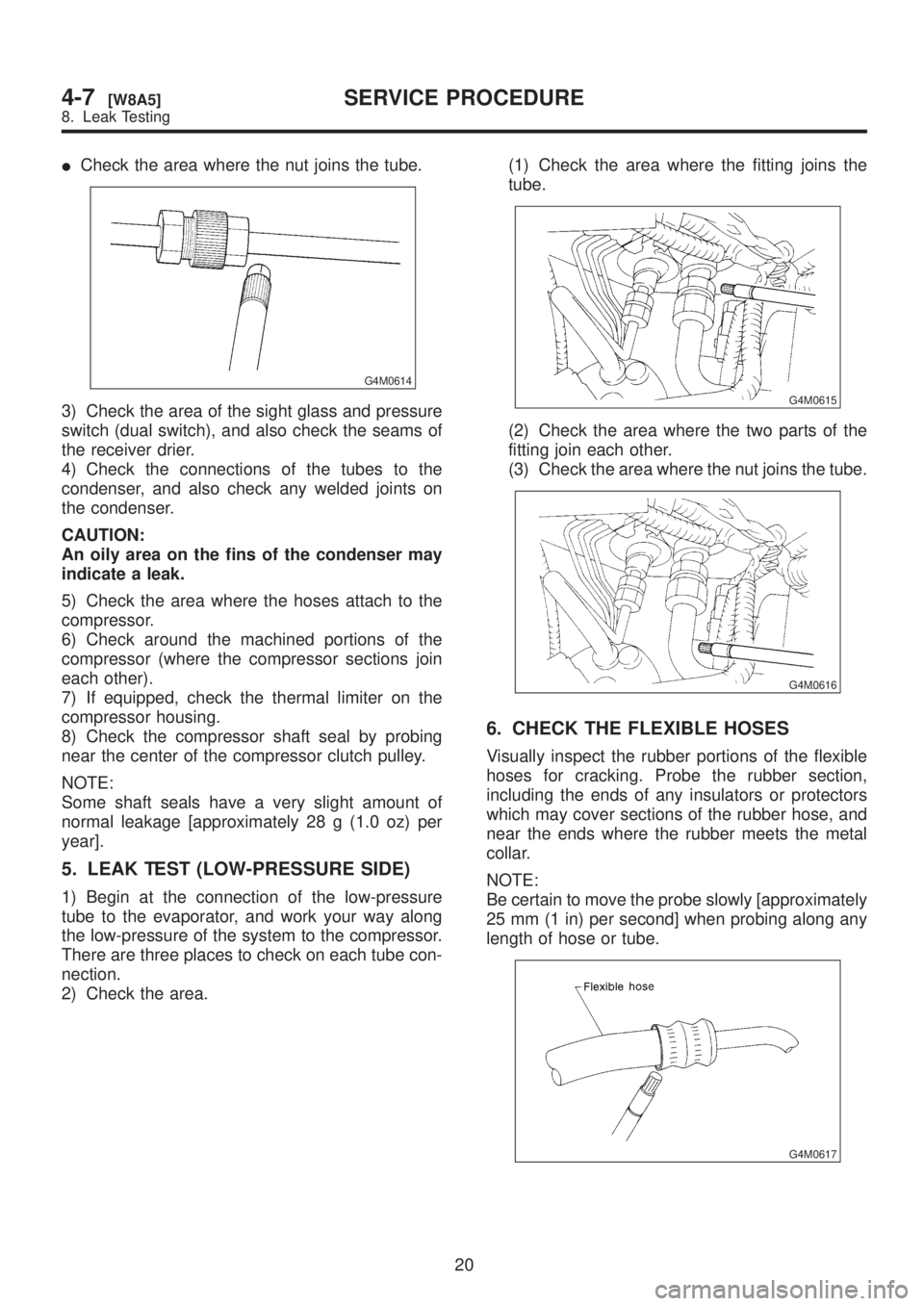
ICheck the area where the nut joins the tube.
G4M0614
3) Check the area of the sight glass and pressure
switch (dual switch), and also check the seams of
the receiver drier.
4) Check the connections of the tubes to the
condenser, and also check any welded joints on
the condenser.
CAUTION:
An oily area on the fins of the condenser may
indicate a leak.
5) Check the area where the hoses attach to the
compressor.
6) Check around the machined portions of the
compressor (where the compressor sections join
each other).
7) If equipped, check the thermal limiter on the
compressor housing.
8) Check the compressor shaft seal by probing
near the center of the compressor clutch pulley.
NOTE:
Some shaft seals have a very slight amount of
normal leakage [approximately 28 g (1.0 oz) per
year].
5. LEAK TEST (LOW-PRESSURE SIDE)
1) Begin at the connection of the low-pressure
tube to the evaporator, and work your way along
the low-pressure of the system to the compressor.
There are three places to check on each tube con-
nection.
2) Check the area.(1) Check the area where the fitting joins the
tube.
G4M0615
(2) Check the area where the two parts of the
fitting join each other.
(3) Check the area where the nut joins the tube.
G4M0616
6. CHECK THE FLEXIBLE HOSES
Visually inspect the rubber portions of the flexible
hoses for cracking. Probe the rubber section,
including the ends of any insulators or protectors
which may cover sections of the rubber hose, and
near the ends where the rubber meets the metal
collar.
NOTE:
Be certain to move the probe slowly [approximately
25 mm (1 in) per second] when probing along any
length of hose or tube.
G4M0617
20
4-7[W8A5]SERVICE PROCEDURE
8. Leak Testing
Page 997 of 1456
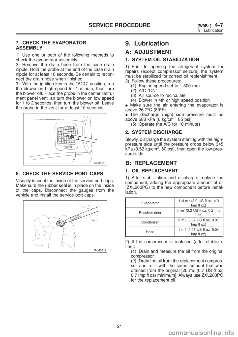
7. CHECK THE EVAPORATOR
ASSEMBLY
1) Use one or both of the following methods to
check the evaporator assembly.
2) Remove the drain hose from the case drain
nipple. Hold the probe at the end of the case drain
nipple for at least 10 seconds. Be certain to recon-
nect the drain hose when finished.
3) With the ignition key in the ªACCº position, run
the blower on high speed for 1 minute, then turn
the blower off. Place the probe in the center instru-
ment panel vent, an turn the blower on low speed
for 1 to 2 seconds, then turn the blower off. Leave
the probe in the vent for at least 10 seconds.
G4M0618
8. CHECK THE SERVICE PORT CAPS
Visually inspect the inside of the service port caps.
Make sure the rubber seal is in place on the inside
of the caps. Disconnect the gauges from the
vehicle and install the service port caps.
G4M0619
9. Lubrication
A: ADJUSTMENT
1. SYSTEM OIL STABILIZATION
1) Prior to opening the refrigerant system for
repairs (except compressor seizure) the system
must be stabilized for correct oil replenishment.
2) Follow these procedures:
(1) Engine speed set to 1,500 rpm
(2) A/C ªONº
(3) Air source to recirculate
(4) Blower in 4th or high speed position
IMake sure the air entering the evaporator is
above 26.7ÉC (80ÉF).
IThe discharge (high) side pressure must be
above 588 kPa (6 kg/cm
2, 85 psi).
(5) Operate the A/C for 10 minutes.
2. SYSTEM DISCHARGE
Slowly, discharge the system starting with the high-
pressure side until the pressure drops below 345
kPa (3.52 kg/cm
2, 50 psi), then open the low-pres-
sure side.
B: REPLACEMENT
1. OIL REPLACEMENT
1) After stabilization and discharge, replace the
component, adding the appropriate amount of oil
(ZXL200PG) to the new component before instal-
lation.
Evaporator11 4 m(3.9 US fl oz, 4.0
Imp fl oz)
Receiver drier5m(0.2 US fl oz, 0.2 Imp
fl oz)
Condenser2m(0.07 US fl oz, 0.07
Imp fl oz)
Hose1m(0.03 US fl oz, 0.04
Imp fl oz)
2) If the compressor is replaced (after stabiliza-
tion):
(1) Drain and measure the oil from the original
compressor.
(2) Drain the oil from the replacement compres-
sor and refill with the same amount that was
drained from the original [20 m(0.7 US fl oz,
0.7 Imp fl oz) minimum]. Always use ZXL200PG
for the replacement oil.
21
[W9B1]4-7SERVICE PROCEDURE
9. Lubrication
Page 998 of 1456
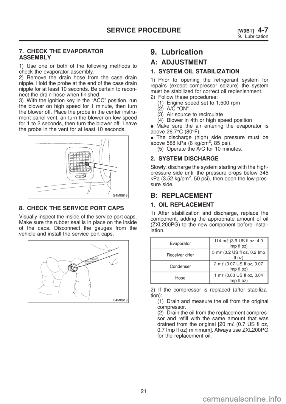
7. CHECK THE EVAPORATOR
ASSEMBLY
1) Use one or both of the following methods to
check the evaporator assembly.
2) Remove the drain hose from the case drain
nipple. Hold the probe at the end of the case drain
nipple for at least 10 seconds. Be certain to recon-
nect the drain hose when finished.
3) With the ignition key in the ªACCº position, run
the blower on high speed for 1 minute, then turn
the blower off. Place the probe in the center instru-
ment panel vent, an turn the blower on low speed
for 1 to 2 seconds, then turn the blower off. Leave
the probe in the vent for at least 10 seconds.
G4M0618
8. CHECK THE SERVICE PORT CAPS
Visually inspect the inside of the service port caps.
Make sure the rubber seal is in place on the inside
of the caps. Disconnect the gauges from the
vehicle and install the service port caps.
G4M0619
9. Lubrication
A: ADJUSTMENT
1. SYSTEM OIL STABILIZATION
1) Prior to opening the refrigerant system for
repairs (except compressor seizure) the system
must be stabilized for correct oil replenishment.
2) Follow these procedures:
(1) Engine speed set to 1,500 rpm
(2) A/C ªONº
(3) Air source to recirculate
(4) Blower in 4th or high speed position
IMake sure the air entering the evaporator is
above 26.7ÉC (80ÉF).
IThe discharge (high) side pressure must be
above 588 kPa (6 kg/cm
2, 85 psi).
(5) Operate the A/C for 10 minutes.
2. SYSTEM DISCHARGE
Slowly, discharge the system starting with the high-
pressure side until the pressure drops below 345
kPa (3.52 kg/cm
2, 50 psi), then open the low-pres-
sure side.
B: REPLACEMENT
1. OIL REPLACEMENT
1) After stabilization and discharge, replace the
component, adding the appropriate amount of oil
(ZXL200PG) to the new component before instal-
lation.
Evaporator11 4 m(3.9 US fl oz, 4.0
Imp fl oz)
Receiver drier5m(0.2 US fl oz, 0.2 Imp
fl oz)
Condenser2m(0.07 US fl oz, 0.07
Imp fl oz)
Hose1m(0.03 US fl oz, 0.04
Imp fl oz)
2) If the compressor is replaced (after stabiliza-
tion):
(1) Drain and measure the oil from the original
compressor.
(2) Drain the oil from the replacement compres-
sor and refill with the same amount that was
drained from the original [20 m(0.7 US fl oz,
0.7 Imp fl oz) minimum]. Always use ZXL200PG
for the replacement oil.
21
[W9B1]4-7SERVICE PROCEDURE
9. Lubrication
Page 1001 of 1456
11. Compressor
A: INSPECTION
1. COMPRESSOR CLUTCH
NOTE:
ICompressor is a swash plate type. When trouble
occurs, replace compressor as a single unit.
ICompressor clutch trouble is often caused by
clutch slippage and noise. Check and take correc-
tive measures, as required.
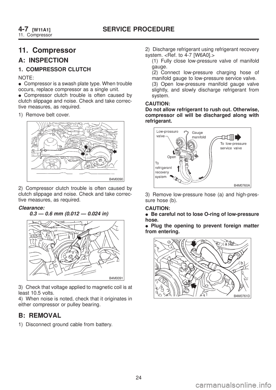
1) Remove belt cover.
B4M0090
2) Compressor clutch trouble is often caused by
clutch slippage and noise. Check and take correc-
tive measures, as required.
Clearance:
0.3 Ð 0.6 mm (0.012 Ð 0.024 in)
B4M0091
3) Check that voltage applied to magnetic coil is at
least 10.5 volts.
4) When noise is noted, check that it originates in
either compressor or pulley bearing.
B: REMOVAL
1) Disconnect ground cable from battery.2) Discharge refrigerant using refrigerant recovery
system.
(1) Fully close low-pressure valve of manifold
gauge.
(2) Connect low-pressure charging hose of
manifold gauge to low-pressure service valve.
(3) Open low-pressure manifold gauge valve
slightly, and slowly discharge refrigerant from
system.
CAUTION:
Do not allow refrigerant to rush out. Otherwise,
compressor oil will be discharged along with
refrigerant.
B4M0760A
3) Remove low-pressure hose (a) and high-pres-
sure hose (b).
CAUTION:
IBe careful not to lose O-ring of low-pressure
hose.
IPlug the opening to prevent foreign matter
from entering.
B4M0761D
24
4-7[W11A1]SERVICE PROCEDURE
11. Compressor
Page 1002 of 1456
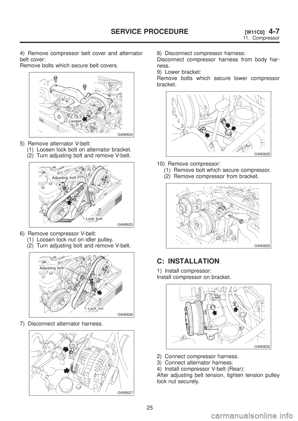
4) Remove compressor belt cover and alternator
belt cover:
Remove bolts which secure belt covers.
G4M0624
5) Remove alternator V-belt:
(1) Loosen lock bolt on alternator bracket.
(2) Turn adjusting bolt and remove V-belt.
G4M0625
6) Remove compressor V-belt:
(1) Loosen lock nut on idler pulley.
(2) Turn adjusting bolt and remove V-belt.
G4M0626
7) Disconnect alternator harness.
G4M0627
8) Disconnect compressor harness:
Disconnect compressor harness from body har-
ness.
9) Lower bracket:
Remove bolts which secure lower compressor
bracket.
G4M0628
10) Remove compressor:
(1) Remove bolt which secure compressor.
(2) Remove compressor from bracket.
G4M0629
C: INSTALLATION
1) Install compressor:
Install compressor on bracket.
G4M0630
2) Connect compressor harness.
3) Connect alternator harness.
4) Install compressor V-belt (Rear):
After adjusting belt tension, tighten tension pulley
lock nut securely.
25
[W11C0]4-7SERVICE PROCEDURE
11. Compressor
Page 1003 of 1456
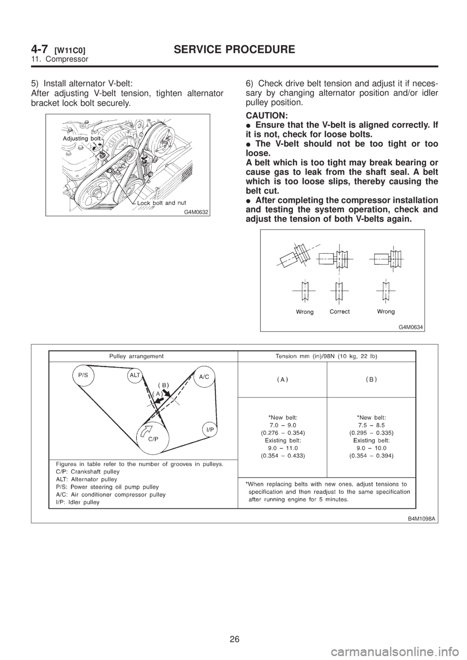
5) Install alternator V-belt:
After adjusting V-belt tension, tighten alternator
bracket lock bolt securely.
G4M0632
6) Check drive belt tension and adjust it if neces-
sary by changing alternator position and/or idler
pulley position.
CAUTION:
IEnsure that the V-belt is aligned correctly. If
it is not, check for loose bolts.
IThe V-belt should not be too tight or too
loose.
A belt which is too tight may break bearing or
cause gas to leak from the shaft seal. A belt
which is too loose slips, thereby causing the
belt cut.
IAfter completing the compressor installation
and testing the system operation, check and
adjust the tension of both V-belts again.
G4M0634
B4M1098A
26
4-7[W11C0]SERVICE PROCEDURE
11. Compressor
Page 1004 of 1456
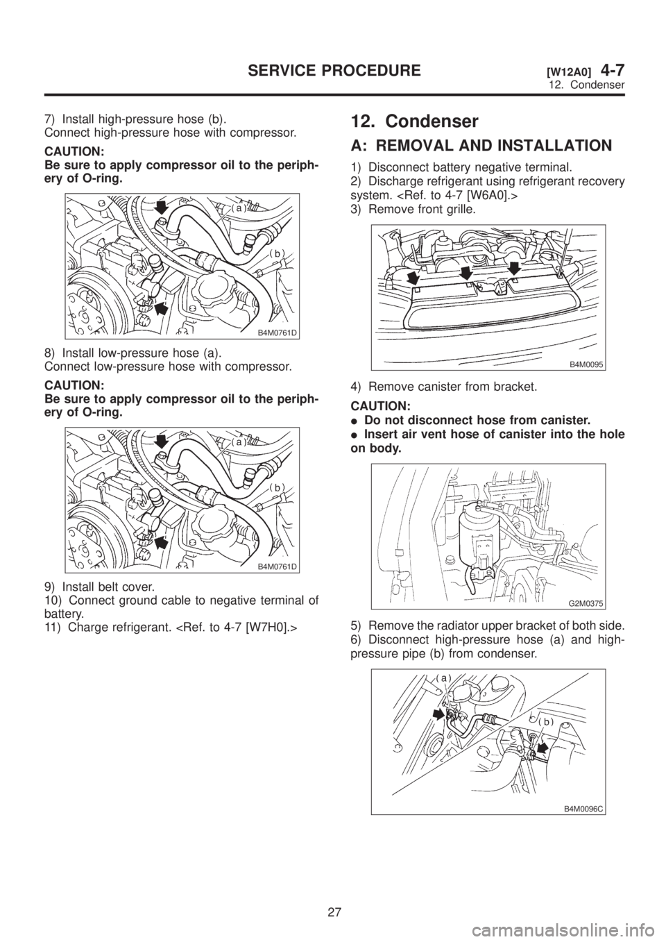
7) Install high-pressure hose (b).
Connect high-pressure hose with compressor.
CAUTION:
Be sure to apply compressor oil to the periph-
ery of O-ring.
B4M0761D
8) Install low-pressure hose (a).
Connect low-pressure hose with compressor.
CAUTION:
Be sure to apply compressor oil to the periph-
ery of O-ring.
B4M0761D
9) Install belt cover.
10) Connect ground cable to negative terminal of
battery.
11) Charge refrigerant.
12. Condenser
A: REMOVAL AND INSTALLATION
1) Disconnect battery negative terminal.
2) Discharge refrigerant using refrigerant recovery
system.
3) Remove front grille.
B4M0095
4) Remove canister from bracket.
CAUTION:
IDo not disconnect hose from canister.
IInsert air vent hose of canister into the hole
on body.
G2M0375
5) Remove the radiator upper bracket of both side.
6) Disconnect high-pressure hose (a) and high-
pressure pipe (b) from condenser.
B4M0096C
27
[W12A0]4-7SERVICE PROCEDURE
12. Condenser