1999 SUBARU LEGACY cooling
[x] Cancel search: coolingPage 229 of 1456
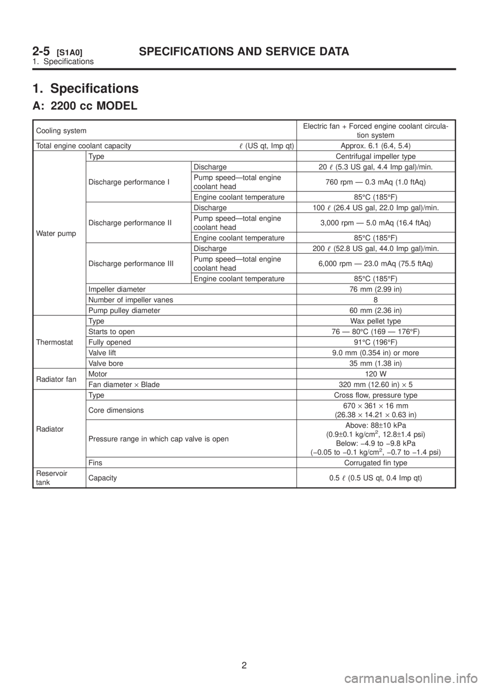
1. Specifications
A: 2200 cc MODEL
Cooling systemElectric fan + Forced engine coolant circula-
tion system
Total engine coolant capacity(US qt, Imp qt) Approx. 6.1 (6.4, 5.4)
Water pumpType Centrifugal impeller type
Discharge performance IDischarge 20(5.3 US gal, 4.4 Imp gal)/min.
Pump speedÐtotal engine
coolant head760 rpm Ð 0.3 mAq (1.0 ftAq)
Engine coolant temperature 85ÉC (185ÉF)
Discharge performance IIDischarge 100(26.4 US gal, 22.0 Imp gal)/min.
Pump speedÐtotal engine
coolant head3,000 rpm Ð 5.0 mAq (16.4 ftAq)
Engine coolant temperature 85ÉC (185ÉF)
Discharge performance IIIDischarge 200(52.8 US gal, 44.0 Imp gal)/min.
Pump speedÐtotal engine
coolant head6,000 rpm Ð 23.0 mAq (75.5 ftAq)
Engine coolant temperature 85ÉC (185ÉF)
Impeller diameter 76 mm (2.99 in)
Number of impeller vanes 8
Pump pulley diameter 60 mm (2.36 in)
ThermostatTypeWax pellet type
Starts to open 76 Ð 80ÉC (169 Ð 176ÉF)
Fully opened 91ÉC (196ÉF)
Valve lift 9.0 mm (0.354 in) or more
Valve bore 35 mm (1.38 in)
Radiator fanMotor120 W
Fan diameter´Blade 320 mm (12.60 in)´5
RadiatorType Cross flow, pressure type
Core dimensions670´361´16 mm
(26.38´14.21´0.63 in)
Pressure range in which cap valve is openAbove: 88±10 kPa
(0.9±0.1 kg/cm
2, 12.8±1.4 psi)
Below: þ4.9 to þ9.8 kPa
(þ0.05 to þ0.1 kg/cm
2, þ0.7 to þ1.4 psi)
FinsCorrugated fin type
Reservoir
tankCapacity 0.5(0.5 US qt, 0.4 Imp qt)
2
2-5[S1A0]SPECIFICATIONS AND SERVICE DATA
1. Specifications
Page 230 of 1456

B: 2500 cc MODEL
Cooling systemElectric fan + Forced engine coolant circula-
tion system
Total engine coolant capacity(US qt, Imp qt) Approx. 6.1 (6.4, 5.4)
Water pumpType Centrifugal impeller type
Discharge performance IDischarge 20(5.3 US gal, 4.4 Imp gal)/min.
Pump speedÐtotal engine
coolant head760 rpm Ð 0.3 mAq (1.0 ftAq)
Engine coolant temperature 85ÉC (185ÉF)
Discharge performance IIDischarge 100(26.4 US gal, 22.0 Imp gal)/min.
Pump speedÐtotal engine
coolant head3,000 rpm Ð 5.0 mAq (16.4 ftAq)
Engine coolant temperature 85ÉC (185ÉF)
Discharge performance IIIDischarge 200(52.8 US gal, 44.0 Imp gal)/min.
Pump speedÐtotal engine
coolant head6,000 rpm Ð 23.0 mAq (75.5 ftAq)
Engine coolant temperature 85ÉC (185ÉF)
Impeller diameter 76 mm (2.99 in)
Number of impeller vanes 8
Pump pulley diameter 60 mm (2.36 in)
ThermostatTypeWax pellet type
Starts to open 76 Ð 80ÉC (169 Ð 176ÉF)
Fully opened 91ÉC (196ÉF)
Valve lift 9.0 mm (0.354 in) or more
Valve bore 35 mm (1.38 in)
Radiator fanMotor120 W (main fan)
140 W (sub fan)
Fan diameter´Blade340 mm (13.39 in)´5 (main fan)
280 mm (11.02 in)´4 (sub fan)
RadiatorType Cross flow, pressure type
Core dimensions670´361´16 mm
(26.38´14.21´0.63 in)
Pressure range in which cap valve is openAbove: 88±10 kPa
(0.9±0.1 kg/cm
2, 12.8±1.4 psi)
Below: þ4.9 to þ9.8 kPa
(þ0.05 to þ0.1 kg/cm
2, þ0.7 to þ1.4 psi)
FinsCorrugated fin type
Reservoir
tankCapacity 0.5(0.5 US qt, 0.4 Imp qt)
2. Service Data
Water pump
Clearance between impeller and caseStandard0.5 Ð 0.7 mm (0.020 Ð 0.028
in)
Limit 1.0 mm (0.039 in)
ªThrustº runout of impeller end 0.5 mm (0.020 in)
3
[S200]2-5SPECIFICATIONS AND SERVICE DATA
2. Service Data
Page 231 of 1456
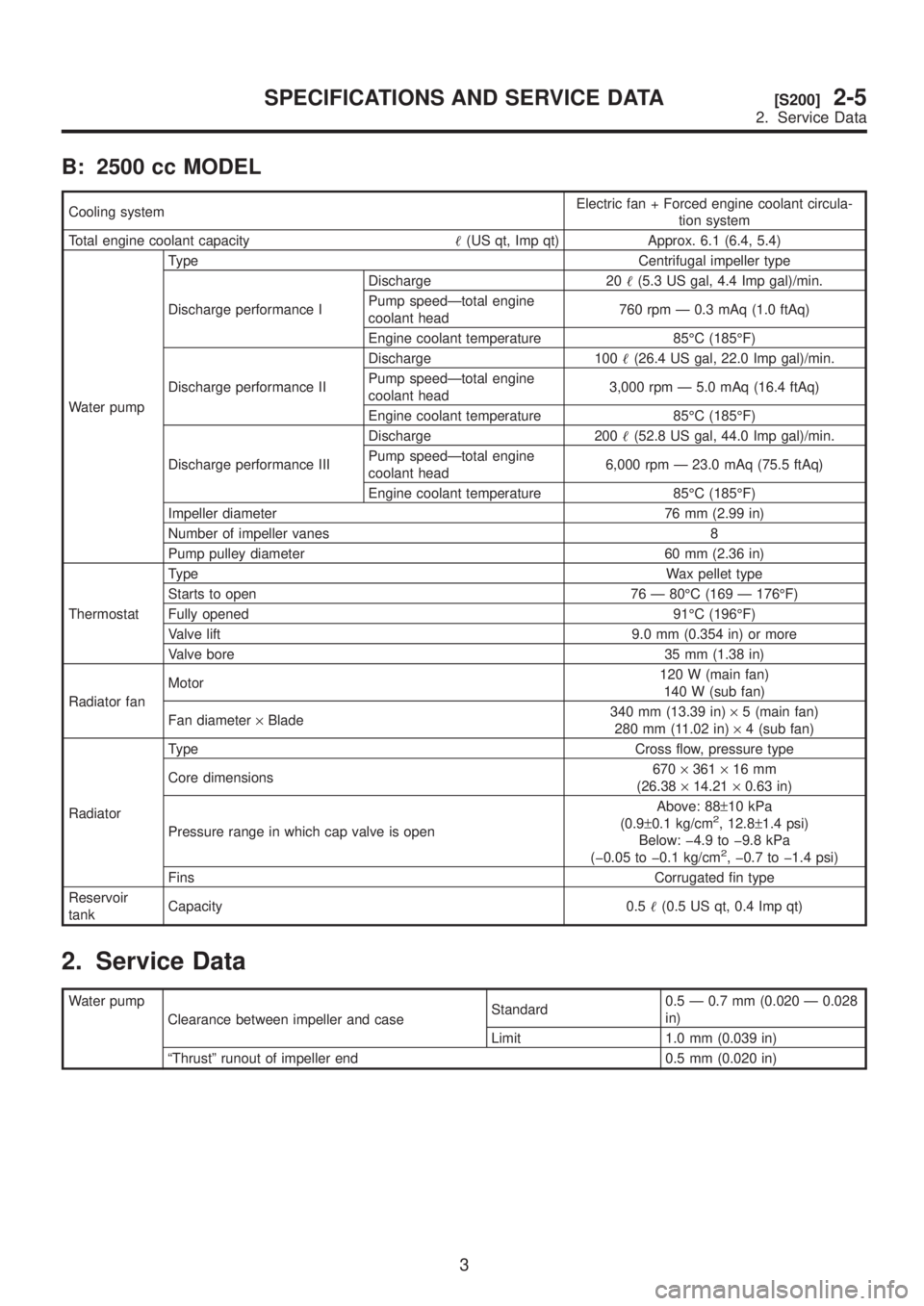
B: 2500 cc MODEL
Cooling systemElectric fan + Forced engine coolant circula-
tion system
Total engine coolant capacity(US qt, Imp qt) Approx. 6.1 (6.4, 5.4)
Water pumpType Centrifugal impeller type
Discharge performance IDischarge 20(5.3 US gal, 4.4 Imp gal)/min.
Pump speedÐtotal engine
coolant head760 rpm Ð 0.3 mAq (1.0 ftAq)
Engine coolant temperature 85ÉC (185ÉF)
Discharge performance IIDischarge 100(26.4 US gal, 22.0 Imp gal)/min.
Pump speedÐtotal engine
coolant head3,000 rpm Ð 5.0 mAq (16.4 ftAq)
Engine coolant temperature 85ÉC (185ÉF)
Discharge performance IIIDischarge 200(52.8 US gal, 44.0 Imp gal)/min.
Pump speedÐtotal engine
coolant head6,000 rpm Ð 23.0 mAq (75.5 ftAq)
Engine coolant temperature 85ÉC (185ÉF)
Impeller diameter 76 mm (2.99 in)
Number of impeller vanes 8
Pump pulley diameter 60 mm (2.36 in)
ThermostatTypeWax pellet type
Starts to open 76 Ð 80ÉC (169 Ð 176ÉF)
Fully opened 91ÉC (196ÉF)
Valve lift 9.0 mm (0.354 in) or more
Valve bore 35 mm (1.38 in)
Radiator fanMotor120 W (main fan)
140 W (sub fan)
Fan diameter´Blade340 mm (13.39 in)´5 (main fan)
280 mm (11.02 in)´4 (sub fan)
RadiatorType Cross flow, pressure type
Core dimensions670´361´16 mm
(26.38´14.21´0.63 in)
Pressure range in which cap valve is openAbove: 88±10 kPa
(0.9±0.1 kg/cm
2, 12.8±1.4 psi)
Below: þ4.9 to þ9.8 kPa
(þ0.05 to þ0.1 kg/cm
2, þ0.7 to þ1.4 psi)
FinsCorrugated fin type
Reservoir
tankCapacity 0.5(0.5 US qt, 0.4 Imp qt)
2. Service Data
Water pump
Clearance between impeller and caseStandard0.5 Ð 0.7 mm (0.020 Ð 0.028
in)
Limit 1.0 mm (0.039 in)
ªThrustº runout of impeller end 0.5 mm (0.020 in)
3
[S200]2-5SPECIFICATIONS AND SERVICE DATA
2. Service Data
Page 236 of 1456
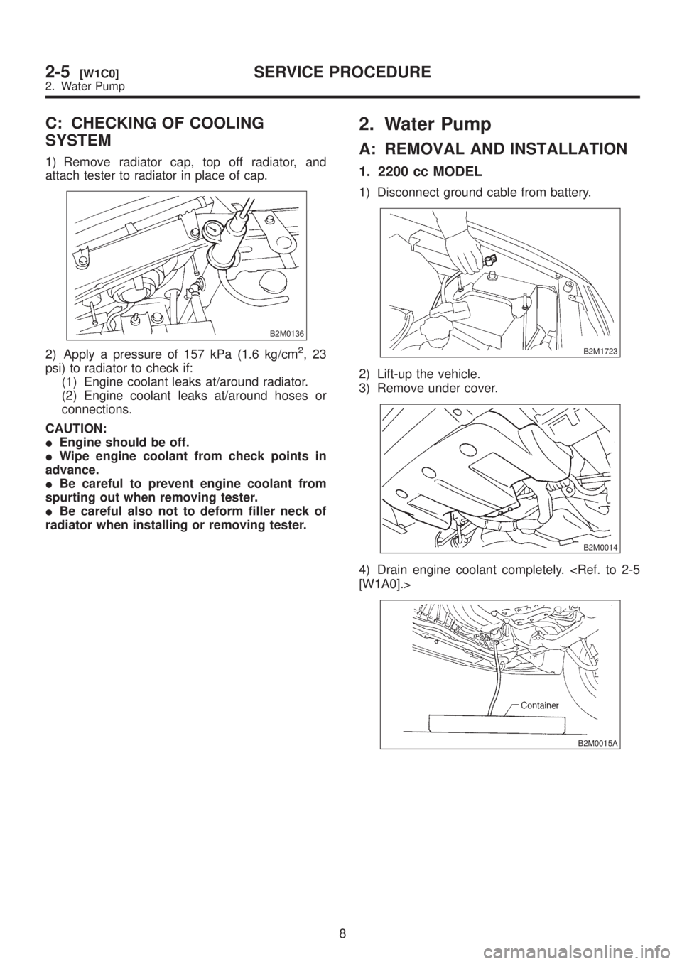
C: CHECKING OF COOLING
SYSTEM
1) Remove radiator cap, top off radiator, and
attach tester to radiator in place of cap.
B2M0136
2) Apply a pressure of 157 kPa (1.6 kg/cm2,23
psi) to radiator to check if:
(1) Engine coolant leaks at/around radiator.
(2) Engine coolant leaks at/around hoses or
connections.
CAUTION:
IEngine should be off.
IWipe engine coolant from check points in
advance.
IBe careful to prevent engine coolant from
spurting out when removing tester.
IBe careful also not to deform filler neck of
radiator when installing or removing tester.
2. Water Pump
A: REMOVAL AND INSTALLATION
1. 2200 cc MODEL
1) Disconnect ground cable from battery.
B2M1723
2) Lift-up the vehicle.
3) Remove under cover.
B2M0014
4) Drain engine coolant completely.
B2M0015A
8
2-5[W1C0]SERVICE PROCEDURE
2. Water Pump
Page 237 of 1456
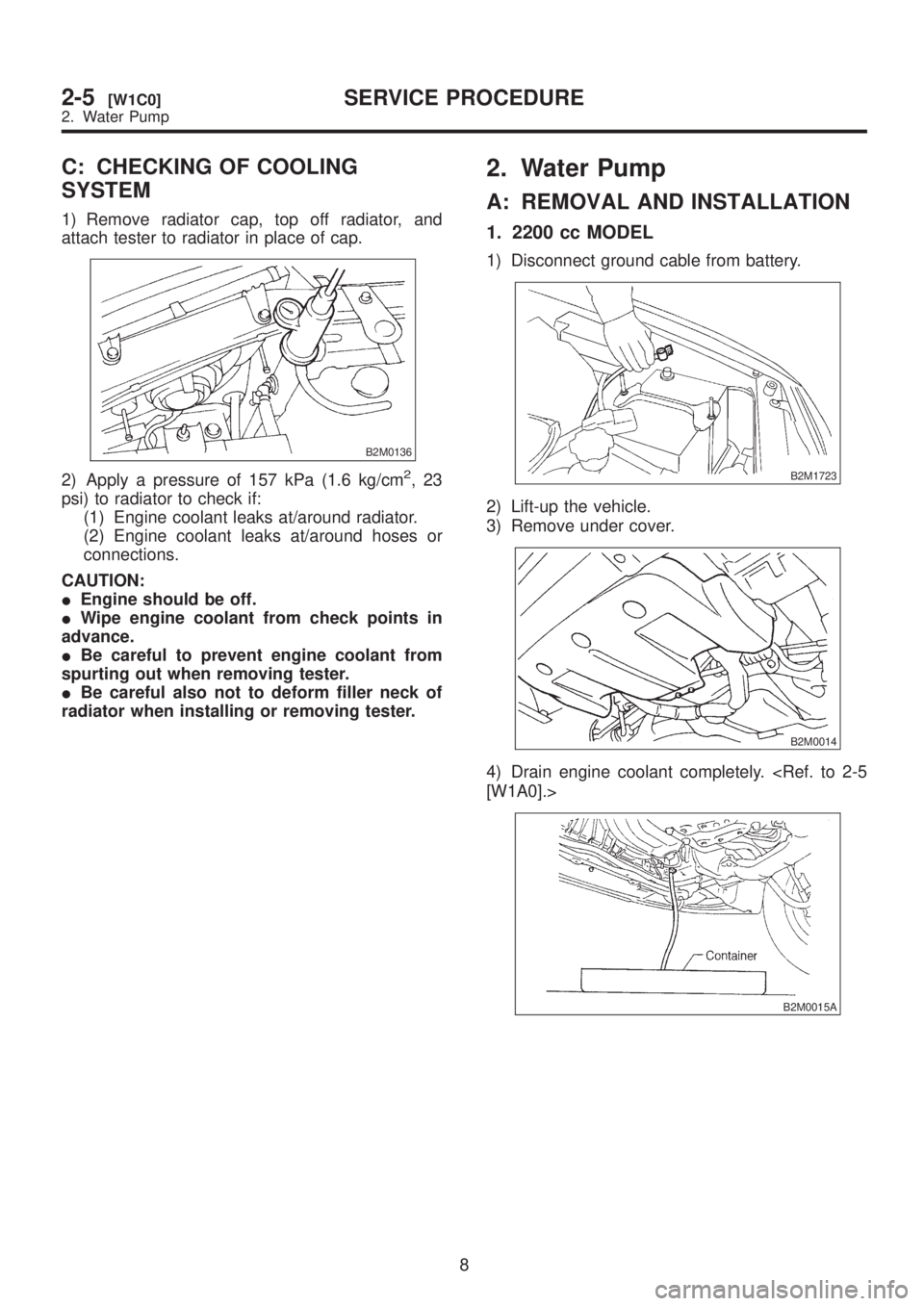
C: CHECKING OF COOLING
SYSTEM
1) Remove radiator cap, top off radiator, and
attach tester to radiator in place of cap.
B2M0136
2) Apply a pressure of 157 kPa (1.6 kg/cm2,23
psi) to radiator to check if:
(1) Engine coolant leaks at/around radiator.
(2) Engine coolant leaks at/around hoses or
connections.
CAUTION:
IEngine should be off.
IWipe engine coolant from check points in
advance.
IBe careful to prevent engine coolant from
spurting out when removing tester.
IBe careful also not to deform filler neck of
radiator when installing or removing tester.
2. Water Pump
A: REMOVAL AND INSTALLATION
1. 2200 cc MODEL
1) Disconnect ground cable from battery.
B2M1723
2) Lift-up the vehicle.
3) Remove under cover.
B2M0014
4) Drain engine coolant completely.
B2M0015A
8
2-5[W1C0]SERVICE PROCEDURE
2. Water Pump
Page 260 of 1456

1. Engine Cooling System Trouble in General
TroubleCorrective action
Over-heatinga. Insufficient engine coolantReplenish engine coolant, inspect for leakage, and
repair.
b. Loose timing belt Repair or replace timing belt tensioner.
c. Oil on drive belt Replace.
d. Malfunction of thermostat Replace.
e. Malfunction of water pump Replace.
f. Clogged engine coolant passage Clean.
g. Improper ignition timingInspect and repair ignition control system.
h. Clogged or leaking radiator Clean or repair, or replace.
i. Improper engine oil in engine coolant Replace engine coolant.
j. Air/fuel mixture ratio too leanInspect and repair fuel injection system.
k. Excessive back pressure in exhaust system Clean or replace.
l. Insufficient clearance between piston and cylinder Adjust or replace.
m. Slipping clutch Repair or replace.
n. Dragging brake Adjust.
o. Improper transmission oil Replace.
p. Defective thermostat Replace.
q. Malfunction of electric fanInspect radiator fan relay, engine coolant temperature
sensor or radiator motor and replace there.
Over-coolinga. Atmospheric temperature extremely low Partly cover radiator front area.
b. Defective thermostat Replace.
Engine coolant
leaks.a. Loosened or damaged connecting units on
hosesRepair or replace.
b. Leakage from water pump Replace.
c. Leakage from water pipe Repair or replace.
d. Leakage around cylinder head gasket Retighten cylinder head bolts or replace gasket.
e. Damaged or cracked cylinder head and crank-
caseRepair or replace.
f. Damaged or cracked thermostat case Repair or replace.
g. Leakage from radiator Repair or replace.
Noisea. Defective drive belt Replace.
b. Defective radiator fan Replace.
c. Defective water pump bearing Replace water pump.
d. Defective water pump mechanical seal Replace water pump.
26
2-5[K100]DIAGNOSTICS
1. Engine Cooling System Trouble in General
Page 395 of 1456

1. Fuel System Trouble in
General
Trouble and possible cause Corrective action
1. Insufficient fuel supply to the injector
1) Fuel pump will not operate.
qDefective terminal contact.Inspect connections, especially ground, and
tighten securely.
qTrouble in electromagnetic or electronic circuit parts. Replace fuel pump.
2) Lowering of fuel pump function. Replace fuel pump.
3) Clogged dust or water in the fuel filter. Replace fuel filter, clean or replace fuel tank.
4) Clogged or bent fuel pipe or hose. Clean, correct or replace fuel pipe or hose.
5) Air is mixed in the fuel system. Inspect or retighten each connection part.
6) Clogged or bent breather tube or pipe.Clean, correct or replace air breather tube or
pipe.
7) Damaged diaphragm of pressure regulator. Replace.
2. Leakage or blow out fuel
1) Loosened joints of the fuel pipe. Retightening.
2) Cracked fuel pipe, hose and fuel tank. Replace.
3) Defective welding part on the fuel tank. Replace.
4) Defective drain packing of the fuel tank. Replace.
5) Clogged or bent air breather tube or air vent tube.Clean, correct or replace air breather tube or air
vent tube.
3.Gasoline smell inside of compartment
1)Loose joints at air breather tube, air vent tube and fuel filler
pipe.Retightening.
2) Defective packing air tightness on the fuel saucer. Correct or replace packing.
3) Cracked fuel separator. Replace separator.
4. Defective fuel meter indicator
1) Defective operation of fuel meter unit. Replace.
2) Defective operation of fuel meter. Replace.
5. Noise
1) Large operation noise or vibration of fuel pump. Replace.
NOTE:
When the vehicle is left unattended for an
extended period of time, water may accumulate in
the fuel tank.
1) To prevent water condensation:
ITop off the fuel tank or drain the fuel completely.
IDrain water condensation from the fuel filter.
2) Refilling the fuel tank:
Refill the fuel tank while there is still some fuel left
in the tank.
3) Protecting the fuel system against freezing and
water condensation:
ICold areas
In snow-covered areas, mountainous areas, skiing
areas, etc. where ambient temperatures drop
below 0ÉC (32ÉF) throughout the winter season,
use an anti-freeze solution in the cooling system.Refueling will also complement the effect of anti-
freeze solution each time the fuel level drops to
about one-half. After the winter season, drain water
which may have accumulated in the fuel filter and
fuel tank in the manner same as that described
under affected areas as below.
IAffected areas
When water condensation is notched in the fuel
filter, drain water from both the fuel filter and fuel
tank or use a water removing agent (or anti-freeze
solution) in the fuel tank.
4) Observe the instructions, notes, etc., indicated
on the label affixed to the anti-freeze solution
(water removing agent) container before use.
27
[K100]2-8DIAGNOSTICS
1. Fuel System Trouble in General
Page 439 of 1456
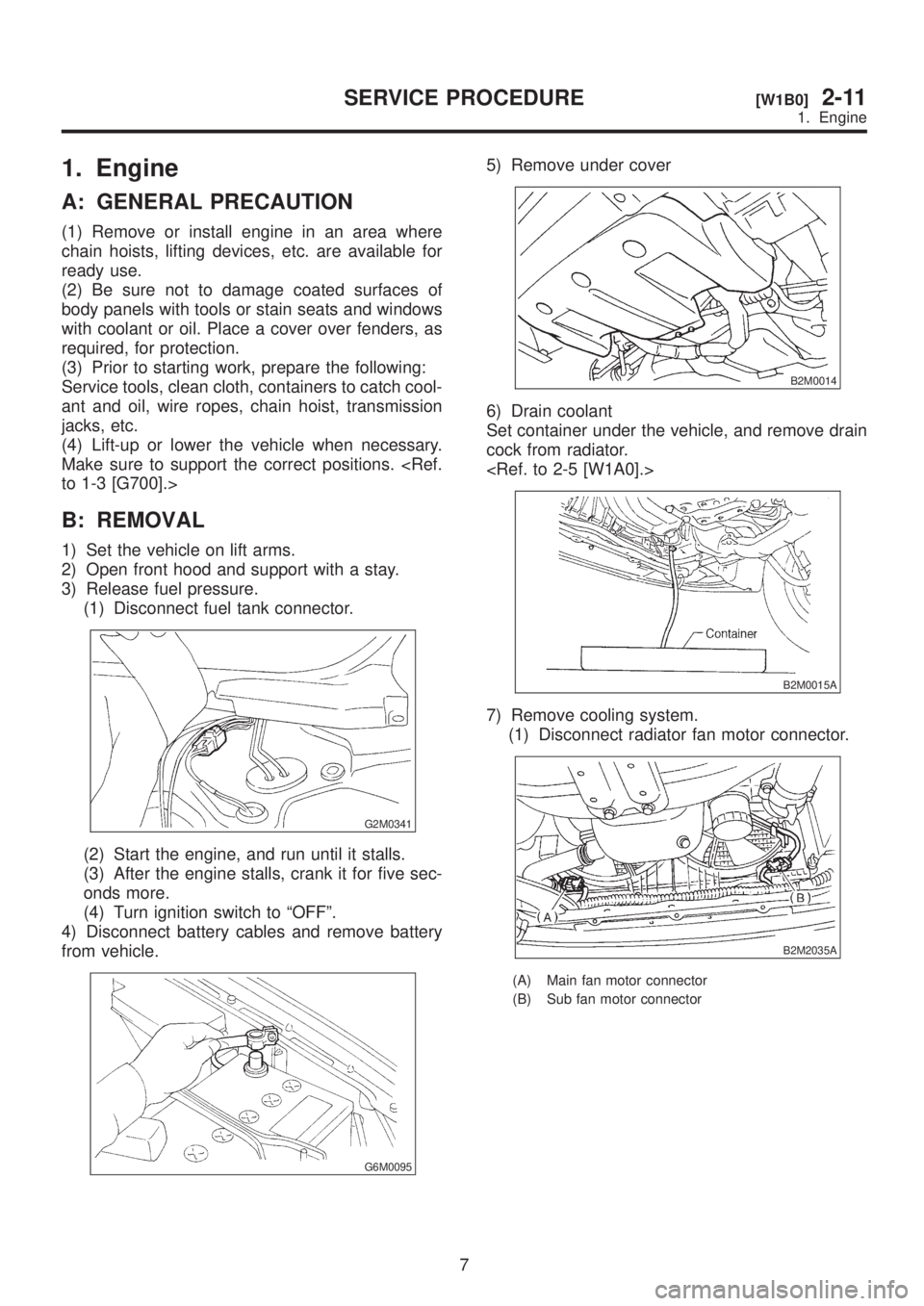
1. Engine
A: GENERAL PRECAUTION
(1) Remove or install engine in an area where
chain hoists, lifting devices, etc. are available for
ready use.
(2) Be sure not to damage coated surfaces of
body panels with tools or stain seats and windows
with coolant or oil. Place a cover over fenders, as
required, for protection.
(3) Prior to starting work, prepare the following:
Service tools, clean cloth, containers to catch cool-
ant and oil, wire ropes, chain hoist, transmission
jacks, etc.
(4) Lift-up or lower the vehicle when necessary.
Make sure to support the correct positions.
B: REMOVAL
1) Set the vehicle on lift arms.
2) Open front hood and support with a stay.
3) Release fuel pressure.
(1) Disconnect fuel tank connector.
G2M0341
(2) Start the engine, and run until it stalls.
(3) After the engine stalls, crank it for five sec-
onds more.
(4) Turn ignition switch to ªOFFº.
4) Disconnect battery cables and remove battery
from vehicle.
G6M0095
5) Remove under cover
B2M0014
6) Drain coolant
Set container under the vehicle, and remove drain
cock from radiator.
B2M0015A
7) Remove cooling system.
(1) Disconnect radiator fan motor connector.
B2M2035A
(A) Main fan motor connector
(B) Sub fan motor connector
7
[W1B0]2-11SERVICE PROCEDURE
1. Engine