Page 60 of 345

3) Conduct appearance inspection on parts
selected.
NOTE:
Also check connector terminals, wiring harness,
case, etc. for damage.
:Is there anything unusual about the
appearance of airbag component
parts?
: Replace faulty airbag component parts.
: Go to step5X2.
5X2 : AIRBAG COMPONENT PARTS
VIBRATION INSPECTION
1) Gently shake check parts (to determine faults.).
2) To check airbag module or roll connector, turn
and tilt steering wheel.
CAUTION:
Do not shake or vibrate airbag control module.
:Does the component malfunction
again when shaking?
: Replace faulty airbag component parts.
: Go to step5X3.
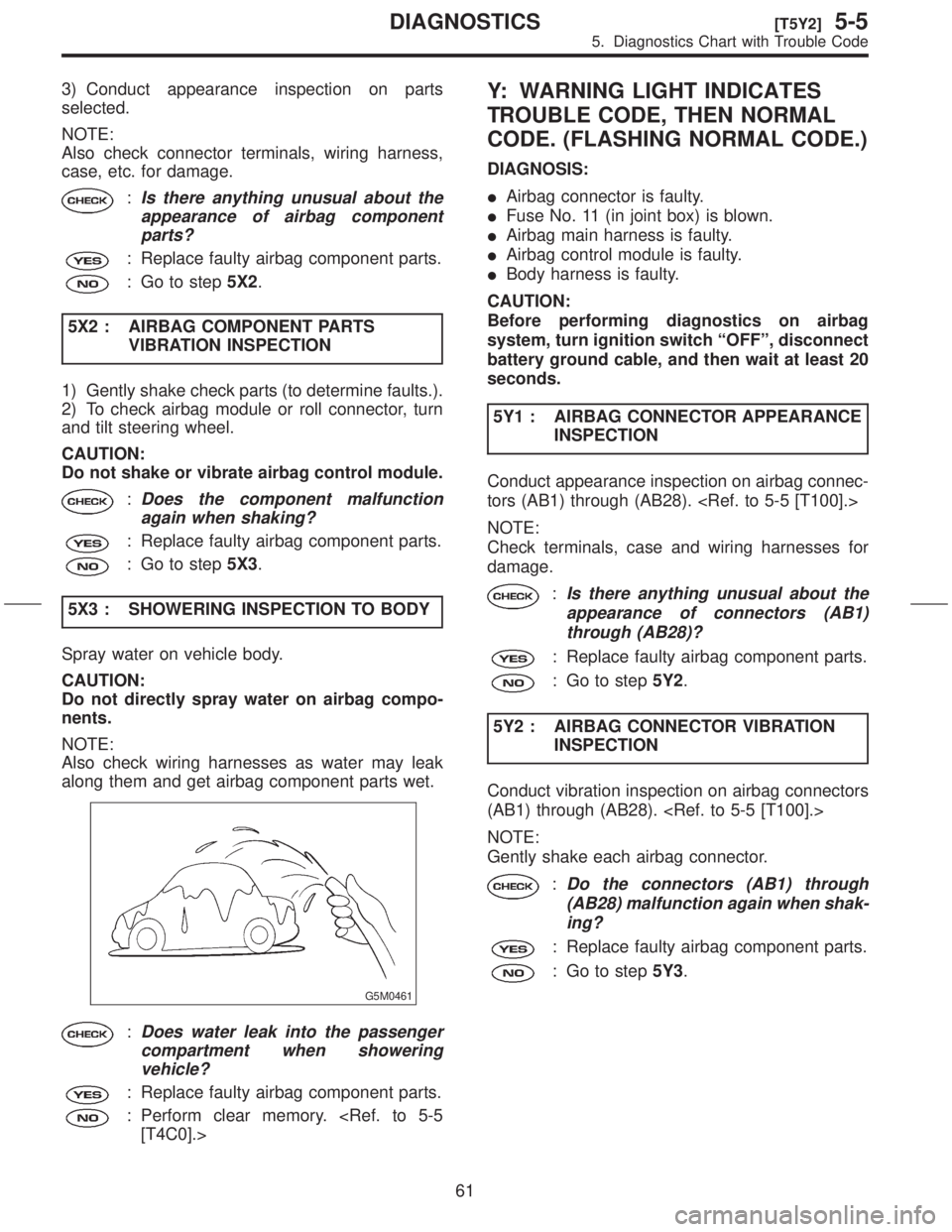
5X3 : SHOWERING INSPECTION TO BODY
Spray water on vehicle body.
CAUTION:
Do not directly spray water on airbag compo-
nents.
NOTE:
Also check wiring harnesses as water may leak
along them and get airbag component parts wet.
G5M0461
:Does water leak into the passenger
compartment when showering
vehicle?
: Replace faulty airbag component parts.
: Perform clear memory.
[T4C0].>
Y: WARNING LIGHT INDICATES
TROUBLE CODE, THEN NORMAL
CODE. (FLASHING NORMAL CODE.)
DIAGNOSIS:
IAirbag connector is faulty.
IFuse No. 11 (in joint box) is blown.
IAirbag main harness is faulty.
IAirbag control module is faulty.
IBody harness is faulty.
CAUTION:
Before performing diagnostics on airbag
system, turn ignition switch ªOFFº, disconnect
battery ground cable, and then wait at least 20
seconds.
5Y1 : AIRBAG CONNECTOR APPEARANCE
INSPECTION
Conduct appearance inspection on airbag connec-
tors (AB1) through (AB28).
NOTE:
Check terminals, case and wiring harnesses for
damage.
:Is there anything unusual about the
appearance of connectors (AB1)
through (AB28)?
: Replace faulty airbag component parts.
: Go to step5Y2.
5Y2 : AIRBAG CONNECTOR VIBRATION
INSPECTION
Conduct vibration inspection on airbag connectors
(AB1) through (AB28).
NOTE:
Gently shake each airbag connector.
:Do the connectors (AB1) through
(AB28) malfunction again when shak-
ing?
: Replace faulty airbag component parts.
: Go to step5Y3.
61
[T5Y2]5-5DIAGNOSTICS
5. Diagnostics Chart with Trouble Code
Page 62 of 345
5Y7 : WARNING LIGHT ILLUMINATION
CHECK
Turn ignition switch ªONº (engine off) and observe
airbag warning light.
:Does the airbag warning light come
on for about 7 seconds, then go out
and stay out?
: Perform clear memory.
[T4C0].>
: Go to ªDIAGNOSTICS PROCEDUREº.
63
[T5Y7]5-5DIAGNOSTICS
5. Diagnostics Chart with Trouble Code
Page 75 of 345

3. Cruise Control System
A: PRECAUTION
1. SUPPLEMENTAL RESTRAINT SYSTEM
ªAIRBAGº
Airbag system wiring harness is routed near the
cruise control module and cruise control command
switch.
CAUTION:
IAll airbag system wiring harness and con-
nectors are yellow. Do not use electrical test
equipment on these circuits.
IBe careful not to damage airbag system wir-
ing harness when servicing the cruise control
module and cruise control command switch.
B: PRE-INSPECTION
1. FUNCTION TESTS
Conduct road tests by selecting a smooth, flat road
or use free rollers for road test simulation.
ICruise Control Main Switch
1) Turn ignition switch to ON.
2) Check that cruise control main switch indicator
light comes on when main switch is pressed (ON).
3) Check that main switch indicator light goes out
when main switch is pressed again (OFF).
4) Turn ignition switch to OFF with main switch ON
(indicated by illumination). Turn ignition switch ON
again to ensure that main switch indicator light
remains OFF.
ICruise Control Command Switch
1) Check that cruise control command switch is
properly set in ªSET/COASTº, ªRESUME/ACCELº,
or ªCANCELº mode.
2) Also check that command switch returns to the
original position when released.
IConstant Speed Test
1) Turn cruise control main switch to ON.
2) Drive the vehicle at a speed greater than 40
km/h (25 MPH).
3) Press command switch to set in ªSET/COASTº
mode.
4) Ensure that vehicle is maintained at the speed
set when command switch was pressed.
IAcceleration Test
1) Set vehicle speed at a speed greater that 40
km/h (25 MPH).
2) Ensure that vehicle continues to accelerate
while holding command switch in ªRESUME/
ACCELº mode, and that vehicle maintains that
optional speed when command switch is released.
IDeceleration Test
1) Set vehicle speed at an optional speed greater
than 40 km/h (25 MPH).
2) Ensure that vehicle continues to decelerate
while holding command switch in ªSET/COASTº
mode, and that it maintains that optional speed
when command switch is released.
NOTE:
When vehicle speed reaches the lower speed limit
of 30 km/h (19 MPH) during deceleration, cruise
control will be released.
2. CRUISE CONTROL CABLE
3B21 : CHECK CRUISE CONTROL CABLE.
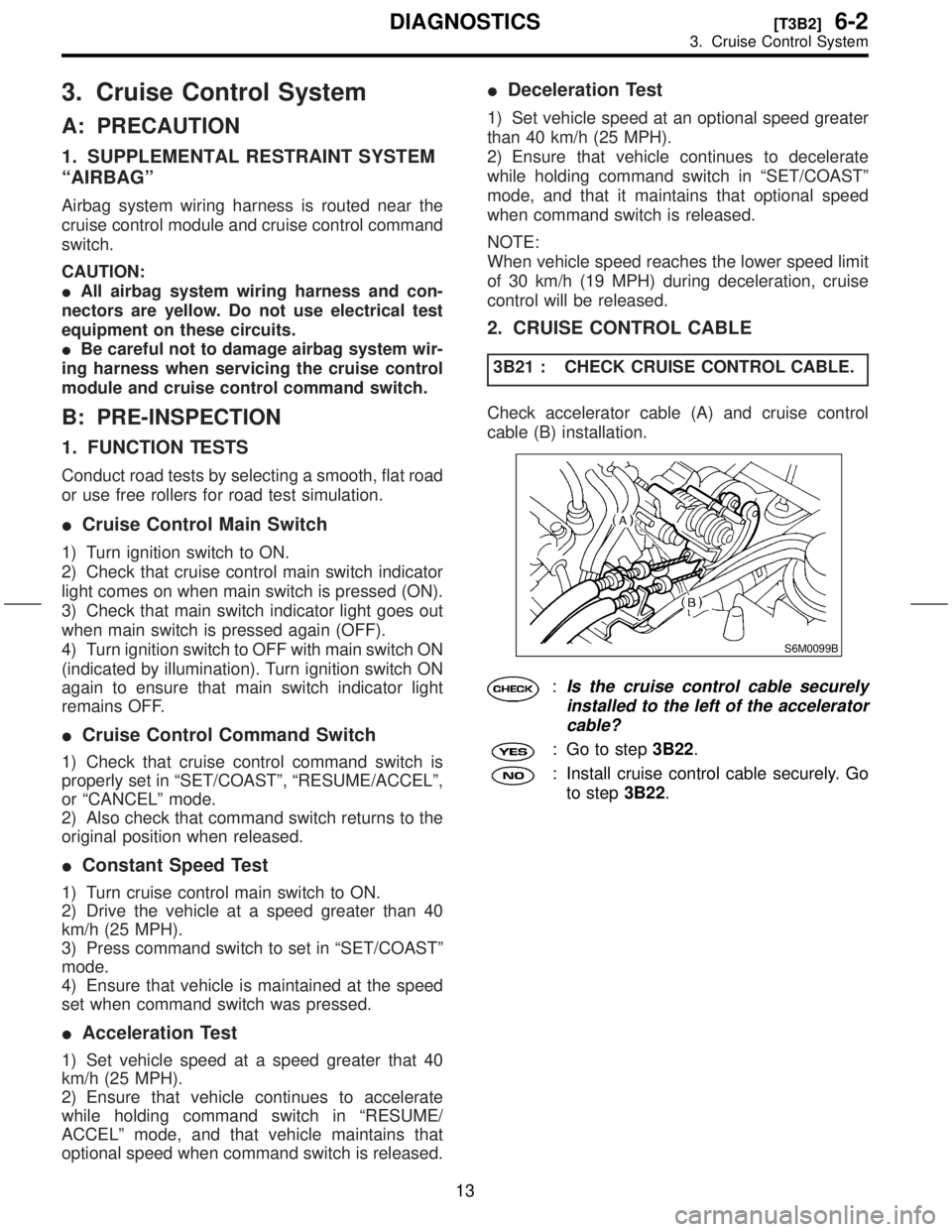
Check accelerator cable (A) and cruise control
cable (B) installation.
S6M0099B
:Is the cruise control cable securely
installed to the left of the accelerator
cable?
: Go to step3B22.
: Install cruise control cable securely. Go
to step3B22.
13
[T3B2]6-2DIAGNOSTICS
3. Cruise Control System
Page 273 of 345
1. General
A: PRECAUTION
IIf any of the airbag system parts such as
sensors, airbag module, airbag control module and
harness are damaged or deformed, replace with
new genuine parts.
G5M0291
IWhen servicing, be sure to turn the ignition
switch off, disconnect the negative (þ) battery ter-
minal then the positive (+) terminal in advance, and
wait for more than 20 seconds before starting
work.
G5M0292
IWhen checking the system, be sure to use a
digital circuit tester. Use of an analog circuit tester
may cause the airbag to activate erroneously. Do
not directly apply the tester probe to any connec-
tor terminal of the airbag. When checking, use a
test harness.
G5M0293
G5M0294
3
[W1A0]5-5SERVICE PROCEDURE
1. General
Page 274 of 345
IDo not drop the airbag modulator parts, subject
it to high temperatures over 90ÉC (194ÉF), or apply
oil, grease, or water to it; otherwise, the internal
parts may be damaged and its reliability greatly
lowered.
G5M0295
IIf any damage or open is found on the SRS air-
bag system wire harness, do not attempt to repair
using soldering, etc. Be sure to replace the faulty
harness with a new genuine part.
G5M0296
IInstall the wire harness securely with the speci-
fied clips so as to avoid interference or jamming
with other parts.
G5M0297
IBefore connecting the airbag system to ground,
make sure that the grounding terminal is free from
paint and contamination.
IDo not allow water or oil to come in contact with
the connector terminals. Do not touch the connec-
tor terminals.
G5M0298
IWhen connecting or disconnecting airbag
connector, make sure ignition switch is OFF.
4
5-5[W1A0]SERVICE PROCEDURE
1. General
Page 280 of 345

1. DRIVER'S AIRBAG MODULE
1) Set front wheels in straight ahead position.
2) Turn ignition switch off.
3) Disconnect ground cable from battery and wait
for at least 20 seconds before starting work.
4) Using TORXTBIT T30, remove the two TORXT
bolts.
H5M0662
5) Disconnect airbag connector on back of airbag
module.
H5M0664
6) Refer toªCAUTIONºfor handling of a removed
airbag module.
7) Install in the reverse order of removal.
CAUTION:
Do not allow harness and connectors to inter-
fere or get caught with other parts.
2. PASSENGER'S AIRBAG MODULE
1) Turn ignition switch off.
2) Disconnect ground cable from battery and wait
for at least 20 seconds before starting work.
3) Remove glove box.
4) Disconnect airbag connector.
[M2F2].>
S5M0214
5) Remove the seven bolts and then carefully
remove airbag module.
S5M0215
6) Refer to ªCAUTIONº for handling of a removed
airbag module.
7) Install in the reverse order of removal.
CAUTION:
Do not allow harness and connectors to inter-
fere or get caught with other parts.
3. SIDE AIRBAG MODULE
The side airbag module cannot be detached from
the front seat assembly. When replacing side air-
bag module, replace front seat assembly.
5-3 [W100].>
10
5-5[W3A1]SERVICE PROCEDURE
3. Airbag Module
Page 283 of 345

5. Side Airbag Harness
A: REMOVAL AND INSTALLATION
1) Turn ignition switch off.
2) Disconnect ground cable from battery and wait
for at least 20 seconds before starting work.
3) Remove front seat and
roll up floor mat .
4) Remove console box.
5) Disconnect the two 12-pin yellow connectors
from airbag control module.
6) Remove side airbag sensor
[W7A0].> and then disconnect connector from side
airbag sensor.
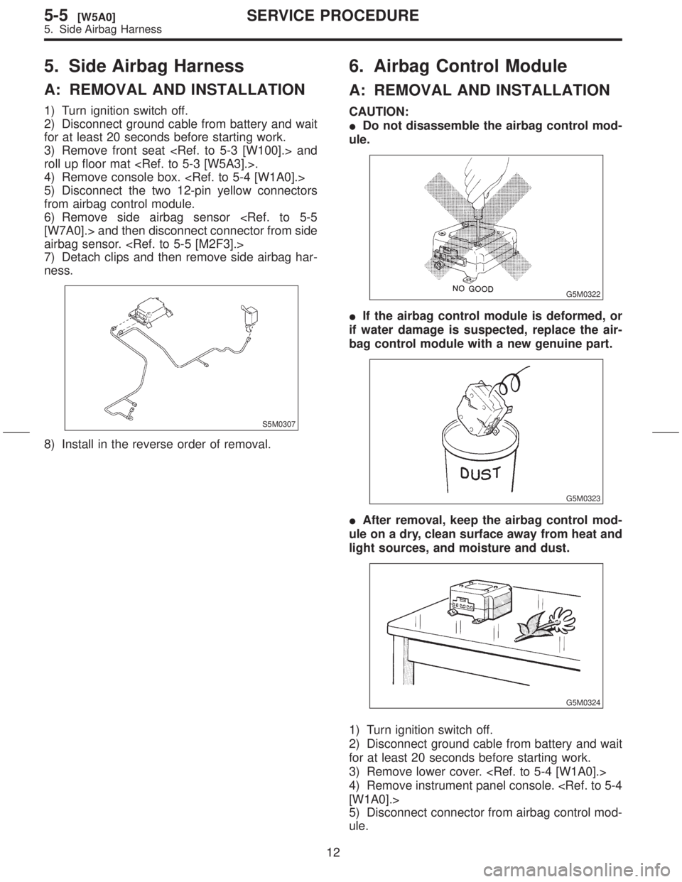
7) Detach clips and then remove side airbag har-
ness.
S5M0307
8) Install in the reverse order of removal.
6. Airbag Control Module
A: REMOVAL AND INSTALLATION
CAUTION:
IDo not disassemble the airbag control mod-
ule.
G5M0322
IIf the airbag control module is deformed, or
if water damage is suspected, replace the air-
bag control module with a new genuine part.
G5M0323
IAfter removal, keep the airbag control mod-
ule on a dry, clean surface away from heat and
light sources, and moisture and dust.
G5M0324
1) Turn ignition switch off.
2) Disconnect ground cable from battery and wait
for at least 20 seconds before starting work.
3) Remove lower cover.
4) Remove instrument panel console.
[W1A0].>
5) Disconnect connector from airbag control mod-
ule.
12
5-5[W5A0]SERVICE PROCEDURE
5. Side Airbag Harness
Page 284 of 345

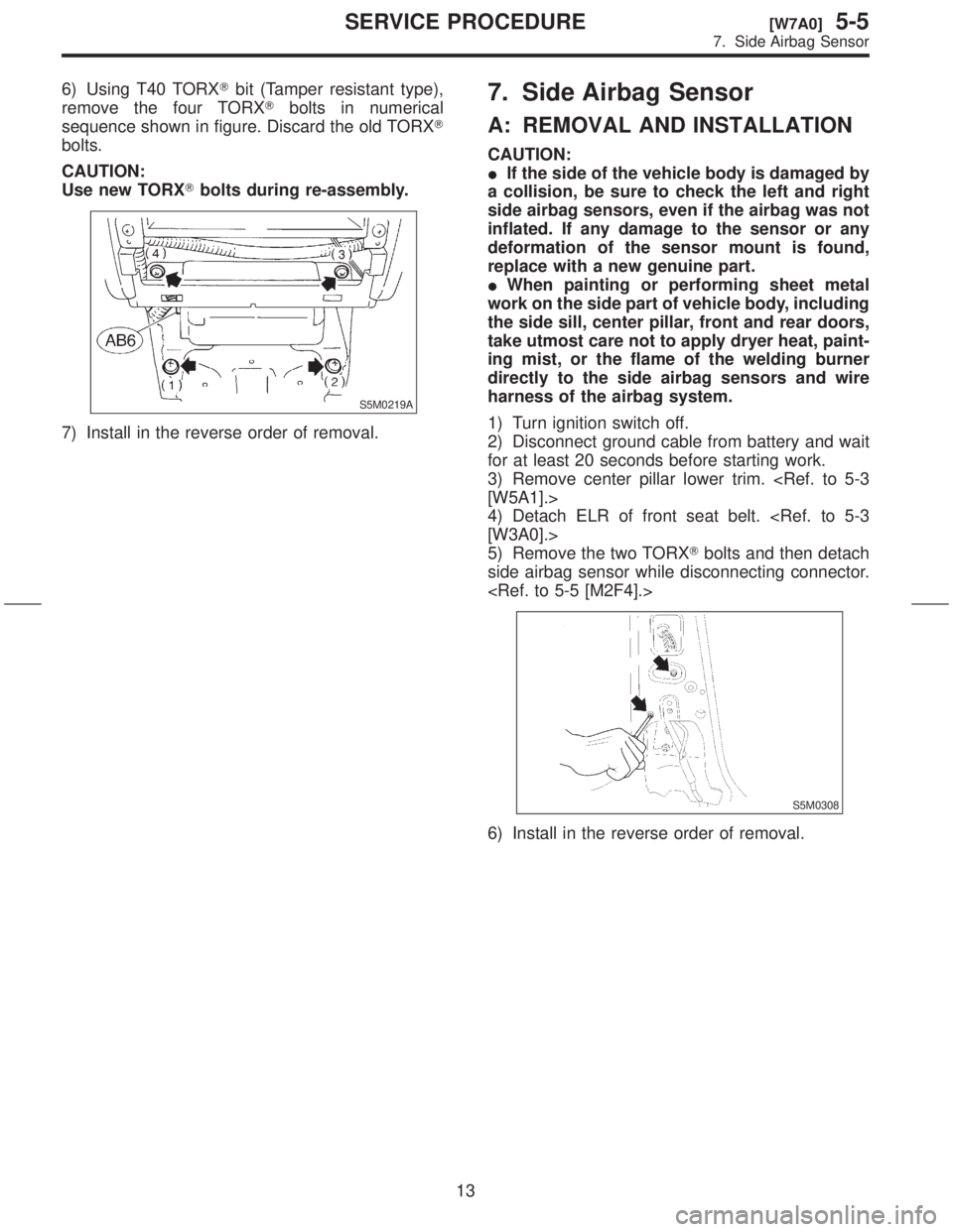
6) Using T40 TORXTbit (Tamper resistant type),
remove the four TORXTbolts in numerical
sequence shown in figure. Discard the old TORXT
bolts.
CAUTION:
Use new TORXTbolts during re-assembly.
S5M0219A
7) Install in the reverse order of removal.
7. Side Airbag Sensor
A: REMOVAL AND INSTALLATION
CAUTION:
IIf the side of the vehicle body is damaged by
a collision, be sure to check the left and right
side airbag sensors, even if the airbag was not
inflated. If any damage to the sensor or any
deformation of the sensor mount is found,
replace with a new genuine part.
IWhen painting or performing sheet metal
work on the side part of vehicle body, including
the side sill, center pillar, front and rear doors,
take utmost care not to apply dryer heat, paint-
ing mist, or the flame of the welding burner
directly to the side airbag sensors and wire
harness of the airbag system.
1) Turn ignition switch off.
2) Disconnect ground cable from battery and wait
for at least 20 seconds before starting work.
3) Remove center pillar lower trim.
[W5A1].>
4) Detach ELR of front seat belt.
[W3A0].>
5) Remove the two TORXTbolts and then detach
side airbag sensor while disconnecting connector.
S5M0308
6) Install in the reverse order of removal.
13
[W7A0]5-5SERVICE PROCEDURE
7. Side Airbag Sensor