Page 91 of 345
H: DIAGNOSTICS CHART WITH DIAGNOSTIC CODE
1. DIAGNOSTIC CODE LIST
Diagnostic
codeItem Contents of diagnosis Index No.
11 BRAKE SW/STOP SW Input signals from brake switch ªOFFº, stop light
switch ªONº
(Brake pedal is depressed.)
12 CLUTCH SW/INHIBITOR SW Input signals from clutch switch ªOFFº (MT), or inhibi-
tor switch ªP or Nº (AT)
[Clutch pedal is depressed (MT), or select lever is set
to P or N position (AT).]
13 LOW SPEED LIMIT Low-speed control limiter
14 CANCEL SW Input signal from cancel switch
(faulty SET/COAST switch or RESUME/ACCEL
switch)
21 VACUUM VALVE Faulty vacuum valve or valve drive system
22 VENT 2 VALVE Faulty vent 2 valve or valve drive system
23 VENT 1 VALVE Faulty vent 1 valve or valve drive system
24 SPEED SENSOR Faulty vehicle speed sensor (MT) or transmission
control module (AT)
25 CONTROL MODULE Faulty CPU RAM included in cruise control module
29
[T3H1]6-2DIAGNOSTICS
3. Cruise Control System
Page 100 of 345
4. DIAGNOSTIC CODE 13 AND 24 (SPEED SENSOR SYSTEM)
DIAGNOSIS:
IDisconnection or short circuit of vehicle speed sensor (MT model) or transmission control module (AT
model).
TROUBLE SYMPTOM:
ICruise control cannot be set. (Cancelled immediately.)
WIRING DIAGRAM:
S6M0421
38
6-2[T3H4]DIAGNOSTICS
3. Cruise Control System
Page 101 of 345

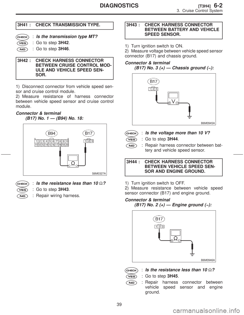
3H41 : CHECK TRANSMISSION TYPE.
:Is the transmission type MT?
: Go to step3H42.
: Go to step3H46.
3H42 : CHECK HARNESS CONNECTOR
BETWEEN CRUISE CONTROL MOD-
ULE AND VEHICLE SPEED SEN-
SOR.
1) Disconnect connector from vehicle speed sen-
sor and cruise control module.
2) Measure resistance of harness connector
between vehicle speed sensor and cruise control
module.
Connector & terminal
(B17) No. 1 Ð (B94) No. 18:
S6M0327A
:Is the resistance less than 10W?
: Go to step3H43.
: Repair wiring harness.3H43 : CHECK HARNESS CONNECTOR
BETWEEN BATTERY AND VEHICLE
SPEED SENSOR.
1) Turn ignition switch to ON.
2) Measure voltage between vehicle speed sensor
connector (B17) and chassis ground.
Connector & terminal
(B17) No. 3 (+) Ð Chassis ground (þ):
B6M0945A
:Is the voltage more than 10 V?
: Go to step3H44.
: Repair harness connector between bat-
tery and vehicle speed sensor.
3H44 : CHECK HARNESS CONNECTOR
BETWEEN VEHICLE SPEED SEN-
SOR AND ENGINE GROUND.
1) Turn ignition switch to OFF.
2) Measure resistance between vehicle speed
sensor connector (B17) and engine ground.
Connector & terminal
(B17) No. 2 (+) Ð Engine ground (þ):
B6M0946A
:Is the resistance less than 10W?
: Go to step3H45.
: Repair harness connector between
vehicle speed sensor and engine
ground.
39
[T3H4]6-2DIAGNOSTICS
3. Cruise Control System
Page 102 of 345

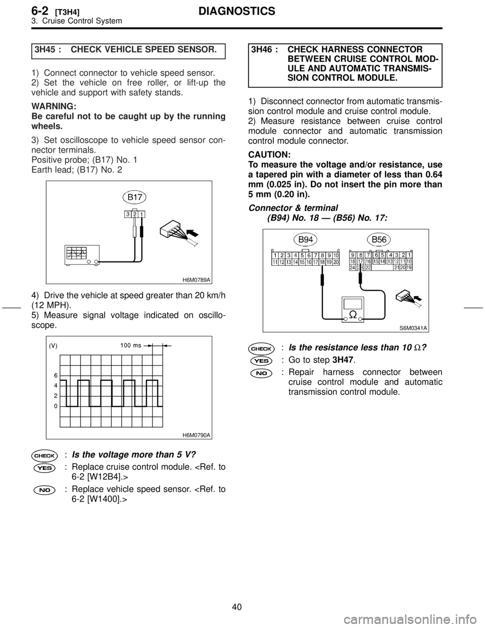
3H45 : CHECK VEHICLE SPEED SENSOR.
1) Connect connector to vehicle speed sensor.
2) Set the vehicle on free roller, or lift-up the
vehicle and support with safety stands.
WARNING:
Be careful not to be caught up by the running
wheels.
3) Set oscilloscope to vehicle speed sensor con-
nector terminals.
Positive probe; (B17) No. 1
Earth lead; (B17) No. 2
H6M0789A
4) Drive the vehicle at speed greater than 20 km/h
(12 MPH).
5) Measure signal voltage indicated on oscillo-
scope.
H6M0790A
:Is the voltage more than 5 V?
: Replace cruise control module.
6-2 [W12B4].>
: Replace vehicle speed sensor.
6-2 [W1400].>3H46 : CHECK HARNESS CONNECTOR
BETWEEN CRUISE CONTROL MOD-
ULE AND AUTOMATIC TRANSMIS-
SION CONTROL MODULE.
1) Disconnect connector from automatic transmis-
sion control module and cruise control module.
2) Measure resistance between cruise control
module connector and automatic transmission
control module connector.
CAUTION:
To measure the voltage and/or resistance, use
a tapered pin with a diameter of less than 0.64
mm (0.025 in). Do not insert the pin more than
5 mm (0.20 in).
Connector & terminal
(B94) No. 18 Ð (B56) No. 17:
S6M0341A
:Is the resistance less than 10W?
: Go to step3H47.
: Repair harness connector between
cruise control module and automatic
transmission control module.
40
6-2[T3H4]DIAGNOSTICS
3. Cruise Control System
Page 259 of 345
3. Front Seat Belt
A: REMOVAL AND INSTALLATION
WARNING:
Replace front seat belt worn by occupants of a
vehicle that has been in a serious accident. The
entire assembly should be replaced even if
damage is not obvious.
1. OUTER BELT
1) Remove anchor cover.
2) Remove shoulder anchor bolt (A).
3) Remove center pillar cover (B).
[W5A1].>
S5M0231B
4) Remove center lower pillar trim panel.
5-3 [W5A1].>
5) Remove webbing guide.
S5M0233
G5M0653
6) Remove lap anchor bolt.
7) Remove belt retractor and outer belt.
S5M0232
8) Install in the reverse order of removal.
CAUTION:
IThe left and right ELR's are not mutually
interchangeable because different sensors are
used.
IBe careful not to twist belts during installa-
tion.
2. INNER BELT
1) Disconnect connector.
2) Remove anchor bolt and then detach inner belt.
S5M0234
3) Install in the reverse order of removal.
10
5-3[W3A0]SERVICE PROCEDURE
3. Front Seat Belt
Page 272 of 345
1. SRS Airbag
S5M0418A
(1) Combination switch ASSY with
roll connector
(2) TORXTbolt T30
(3) Airbag module ASSY (Driver)
(4) Airbag module ASSY (Passen-
ger)
(5) Airbag control module
(6) TORXTbolt T40
(7) Side airbag sensor(8) Side airbag module
(9) Side airbag harness (RH)
(10) Side airbag harness (LH)
(11) Airbag main harness
(12) Front sub sensor (RH)
(13) Front sub sensor harness (RH)
(14) Front sub sensor harness (LH)
(15) Front sub sensor (LH)Tightening torque: N´m (kg-m, ft-lb)
T1:
4.4±1.5 (0.45±0.15, 3.3±1.1)
T2:7.4±2.0 (0.75±0.2, 5.4±1.4)
T3:10±2 (1.0±0.2, 7.2±1.4)
T4:20±4 (2.0±0.4, 14.5±2.9)
T5:25±2 (2.5±0.2, 18.1±1.4)
2
5-5[C100]COMPONENT PARTS
1. SRS Airbag
Page 273 of 345
1. General
A: PRECAUTION
IIf any of the airbag system parts such as
sensors, airbag module, airbag control module and
harness are damaged or deformed, replace with
new genuine parts.
G5M0291
IWhen servicing, be sure to turn the ignition
switch off, disconnect the negative (þ) battery ter-
minal then the positive (+) terminal in advance, and
wait for more than 20 seconds before starting
work.
G5M0292
IWhen checking the system, be sure to use a
digital circuit tester. Use of an analog circuit tester
may cause the airbag to activate erroneously. Do
not directly apply the tester probe to any connec-
tor terminal of the airbag. When checking, use a
test harness.
G5M0293
G5M0294
3
[W1A0]5-5SERVICE PROCEDURE
1. General
Page 277 of 345

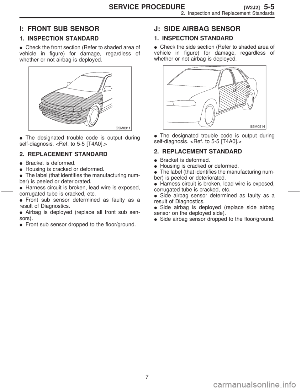
I: FRONT SUB SENSOR
1. INSPECTION STANDARD
ICheck the front section (Refer to shaded area of
vehicle in figure) for damage, regardless of
whether or not airbag is deployed.
G5M0311
IThe designated trouble code is output during
self-diagnosis.
2. REPLACEMENT STANDARD
IBracket is deformed.
IHousing is cracked or deformed.
IThe label (that identifies the manufacturing num-
ber) is peeled or deteriorated.
IHarness circuit is broken, lead wire is exposed,
corrugated tube is cracked, etc.
IFront sub sensor determined as faulty as a
result of Diagnostics.
IAirbag is deployed (replace all front sub sen-
sors).
IFront sub sensor dropped to the floor/ground.
J: SIDE AIRBAG SENSOR
1. INSPECTION STANDARD
ICheck the side section (Refer to shaded area of
vehicle in figure) for damage, regardless of
whether or not airbag is deployed.
B5M0514
IThe designated trouble code is output during
self-diagnosis.
2. REPLACEMENT STANDARD
IBracket is deformed.
IHousing is cracked or deformed.
IThe label (that identifies the manufacturing num-
ber) is peeled or deteriorated.
IHarness circuit is broken, lead wire is exposed,
corrugated tube is cracked, etc.
ISide airbag sensor determined as faulty as a
result of Diagnostics.
ISide airbag is deployed (replace side airbag
sensor on the deployed side).
ISide airbag sensor dropped to the floor/ground.
7
[W2J2]5-5SERVICE PROCEDURE
2. Inspection and Replacement Standards