1999 SUBARU FORESTER fuse
[x] Cancel search: fusePage 139 of 345
![SUBARU FORESTER 1999 Service Repair Manual 5F117 : CHECK PASSIVE ARM.
1) Remove the drivers side sill cover. <Ref. to 5-3
[W5A0].>
2) Connect the white connector (1-pin) at driver
side front lower pillar.
3) Close all doors and the rear gate.](/manual-img/17/57427/w960_57427-138.png "SUBARU FORESTER 1999 Service Repair Manual 5F117 : CHECK PASSIVE ARM.
1) Remove the drivers side sill cover. <Ref. to 5-3
[W5A0].>
2) Connect the white connector (1-pin) at driver
side front lower pillar.
3) Close all doors and the rear gate.")
5F117 : CHECK PASSIVE ARM.
1) Remove the driver's side sill cover.
2) Connect the white connector (1-pin) at driver
side front lower pillar.
3) Close all doors and the rear gate.
:Does the arming automatically func-
tion after 1 minute?
: Go to step5F118.
: Go to step5 F 111.
5F118 : CHECK BATTERY DISCONNECT
PROTECTION.
1) Press the UNLOCK/DISARM button.
2) Connect the white connector (1-pin) at front pil-
lar lower.
3) Install the driver's side sill cover.
4) Open the front hood.
5) Press the LOCK/ARM button.
6) Disconnect the ground cable from battery.
7) Connect the ground cable to battery.
:Does re-arming function automati-
cally?
: End of basic diagnostics procedure.
Press the UNLOCK/DISARM button,
and then close all doors and the rear
gate. Perform ignition switch position
turned LOCK to ON to LOCK.
: Replace security control module.
2. DIAGNOSTICS ITEM 1
5F21 : CHECK FUSE.
Remove and visually check fuse No. 7 (in main
fuse box).
:Is fuse No. 7 blown?
: Replace fuse (20 A).
: Go to step5F22.
5F22 : CHECK FUSE.
Remove and visually check fuse No. 5 (in fuse
box).
:Is fuse No. 5 blown?
: Replace fuse (10 A).
: Go to step5F23.
5F23 : CHECK CLEARANCE LIGHT BULB.
Remove and visually check each clearance light
bulb.
:Is the bulb blown?
: Replace clearance light bulb.
: Go to step5F24.
5F24 : CHECK POWER SUPPLY FOR
CLEARANCE LIGHT.
Measure voltage between main fuse box connec-
tor (F68) and chassis ground.
Connector & terminal
(F68) No. 4 (+) Ð Chassis ground (þ):
B6M1357A
:Is the voltage more than 10 V?
: Go to step5F25.
: Repair wiring harness between main
fuse box and battery.
77
[T5F2]6-2DIAGNOSTICS
5. Security System
Page 140 of 345
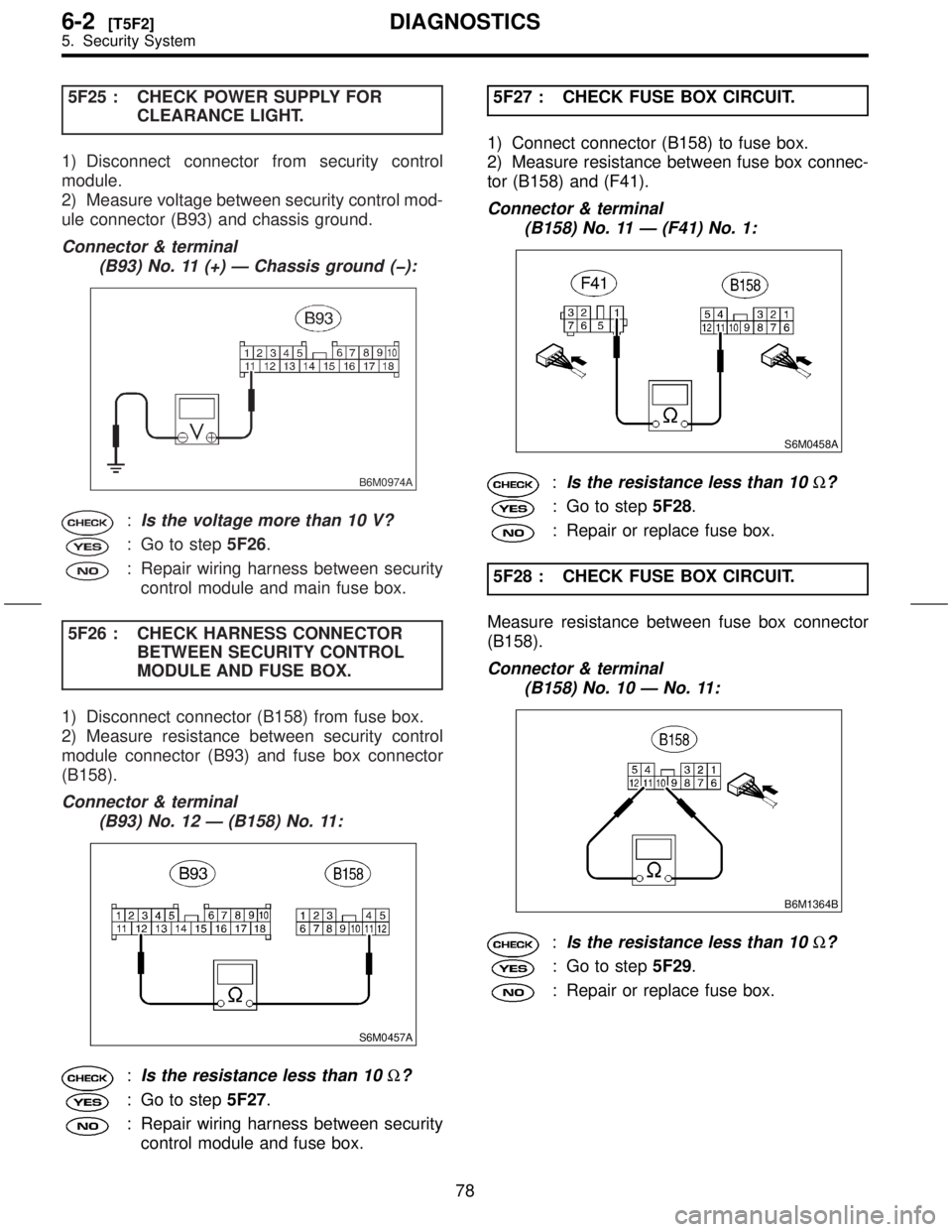
5F25 : CHECK POWER SUPPLY FOR
CLEARANCE LIGHT.
1) Disconnect connector from security control
module.
2) Measure voltage between security control mod-
ule connector (B93) and chassis ground.
Connector & terminal
(B93) No. 11 (+) Ð Chassis ground (þ):
B6M0974A
:Is the voltage more than 10 V?
: Go to step5F26.
: Repair wiring harness between security
control module and main fuse box.
5F26 : CHECK HARNESS CONNECTOR
BETWEEN SECURITY CONTROL
MODULE AND FUSE BOX.
1) Disconnect connector (B158) from fuse box.
2) Measure resistance between security control
module connector (B93) and fuse box connector
(B158).
Connector & terminal
(B93) No. 12 Ð (B158) No. 11:
S6M0457A
:Is the resistance less than 10W?
: Go to step5F27.
: Repair wiring harness between security
control module and fuse box.5F27 : CHECK FUSE BOX CIRCUIT.
1) Connect connector (B158) to fuse box.
2) Measure resistance between fuse box connec-
tor (B158) and (F41).
Connector & terminal
(B158) No. 11 Ð (F41) No. 1:
S6M0458A
:Is the resistance less than 10W?
: Go to step5F28.
: Repair or replace fuse box.
5F28 : CHECK FUSE BOX CIRCUIT.
Measure resistance between fuse box connector
(B158).
Connector & terminal
(B158) No. 10 Ð No. 11:
B6M1364B
:Is the resistance less than 10W?
: Go to step5F29.
: Repair or replace fuse box.
78
6-2[T5F2]DIAGNOSTICS
5. Security System
Page 141 of 345
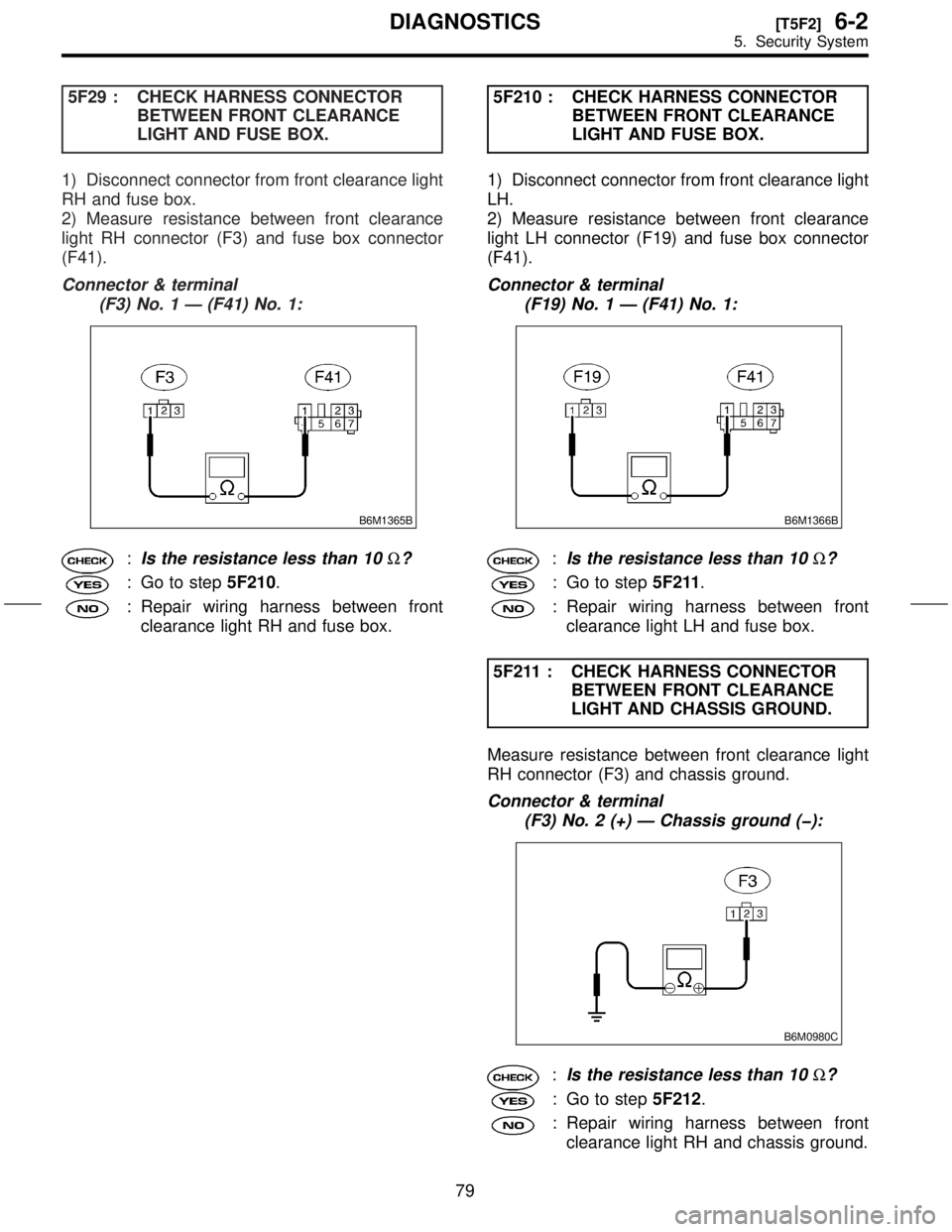
5F29 : CHECK HARNESS CONNECTOR
BETWEEN FRONT CLEARANCE
LIGHT AND FUSE BOX.
1) Disconnect connector from front clearance light
RH and fuse box.
2) Measure resistance between front clearance
light RH connector (F3) and fuse box connector
(F41).
Connector & terminal
(F3) No. 1 Ð (F41) No. 1:
B6M1365B
:Is the resistance less than 10W?
: Go to step5F210.
: Repair wiring harness between front
clearance light RH and fuse box.5F210 : CHECK HARNESS CONNECTOR
BETWEEN FRONT CLEARANCE
LIGHT AND FUSE BOX.
1) Disconnect connector from front clearance light
LH.
2) Measure resistance between front clearance
light LH connector (F19) and fuse box connector
(F41).
Connector & terminal
(F19) No. 1 Ð (F41) No. 1:
B6M1366B
:Is the resistance less than 10W?
: Go to step5F211.
: Repair wiring harness between front
clearance light LH and fuse box.
5F211 : CHECK HARNESS CONNECTOR
BETWEEN FRONT CLEARANCE
LIGHT AND CHASSIS GROUND.
Measure resistance between front clearance light
RH connector (F3) and chassis ground.
Connector & terminal
(F3) No. 2 (+) Ð Chassis ground (þ):
B6M0980C
:Is the resistance less than 10W?
: Go to step5F212.
: Repair wiring harness between front
clearance light RH and chassis ground.
79
[T5F2]6-2DIAGNOSTICS
5. Security System
Page 142 of 345
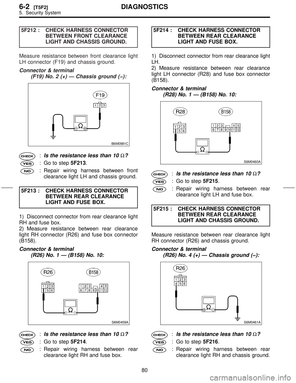
5F212 : CHECK HARNESS CONNECTOR
BETWEEN FRONT CLEARANCE
LIGHT AND CHASSIS GROUND.
Measure resistance between front clearance light
LH connector (F19) and chassis ground.
Connector & terminal
(F19) No. 2 (+) Ð Chassis ground (þ):
B6M0981C
:Is the resistance less than 10W?
: Go to step5F213.
: Repair wiring harness between front
clearance light LH and chassis ground.
5F213 : CHECK HARNESS CONNECTOR
BETWEEN REAR CLEARANCE
LIGHT AND FUSE BOX.
1) Disconnect connector from rear clearance light
RH and fuse box.
2) Measure resistance between rear clearance
light RH connector (R26) and fuse box connector
(B158).
Connector & terminal
(R26) No. 1 Ð (B158) No. 10:
S6M0459A
:Is the resistance less than 10W?
: Go to step5F214.
: Repair wiring harness between rear
clearance light RH and fuse box.5F214 : CHECK HARNESS CONNECTOR
BETWEEN REAR CLEARANCE
LIGHT AND FUSE BOX.
1) Disconnect connector from rear clearance light
LH.
2) Measure resistance between rear clearance
light LH connector (R28) and fuse box connector
(B158).
Connector & terminal
(R28) No. 1 Ð (B158) No. 10:
S6M0460A
:Is the resistance less than 10W?
: Go to step5F215.
: Repair wiring harness between rear
clearance light LH and fuse box.
5F215 : CHECK HARNESS CONNECTOR
BETWEEN REAR CLEARANCE
LIGHT AND CHASSIS GROUND.
Measure resistance between rear clearance light
RH connector (R26) and chassis ground.
Connector & terminal
(R26) No. 4 (+) Ð Chassis ground (þ):
S6M0461A
:Is the resistance less than 10W?
: Go to step5F216.
: Repair wiring harness between rear
clearance light RH and chassis ground.
80
6-2[T5F2]DIAGNOSTICS
5. Security System
Page 143 of 345
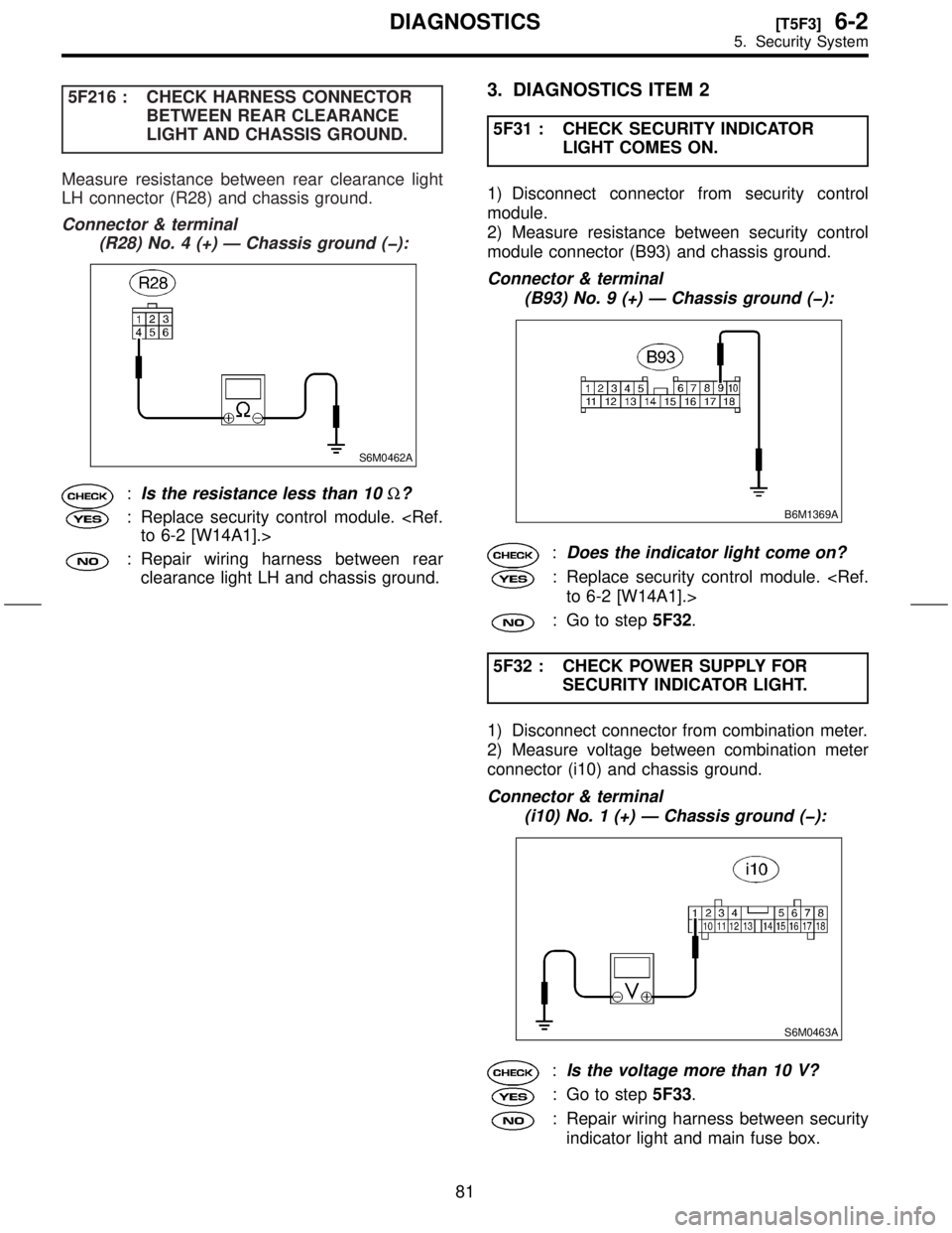
5F216 : CHECK HARNESS CONNECTOR
BETWEEN REAR CLEARANCE
LIGHT AND CHASSIS GROUND.
Measure resistance between rear clearance light
LH connector (R28) and chassis ground.
Connector & terminal
(R28) No. 4 (+) Ð Chassis ground (þ):
S6M0462A
:Is the resistance less than 10W?
: Replace security control module.
: Repair wiring harness between rear
clearance light LH and chassis ground.
3. DIAGNOSTICS ITEM 2
5F31 : CHECK SECURITY INDICATOR
LIGHT COMES ON.
1) Disconnect connector from security control
module.
2) Measure resistance between security control
module connector (B93) and chassis ground.
Connector & terminal
(B93) No. 9 (+) Ð Chassis ground (þ):
B6M1369A
:Does the indicator light come on?
: Replace security control module.
: Go to step5F32.
5F32 : CHECK POWER SUPPLY FOR
SECURITY INDICATOR LIGHT.
1) Disconnect connector from combination meter.
2) Measure voltage between combination meter
connector (i10) and chassis ground.
Connector & terminal
(i10) No. 1 (+) Ð Chassis ground (þ):
S6M0463A
:Is the voltage more than 10 V?
: Go to step5F33.
: Repair wiring harness between security
indicator light and main fuse box.
81
[T5F3]6-2DIAGNOSTICS
5. Security System
Page 146 of 345
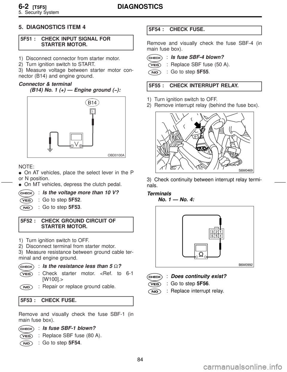
5. DIAGNOSTICS ITEM 4
5F51 : CHECK INPUT SIGNAL FOR
STARTER MOTOR.
1) Disconnect connector from starter motor.
2) Turn ignition switch to START.
3) Measure voltage between starter motor con-
nector (B14) and engine ground.
Connector & terminal
(B14) No. 1 (+) Ð Engine ground (þ):
OBD0100A
NOTE:
IOn AT vehicles, place the select lever in the P
or N position.
IOn MT vehicles, depress the clutch pedal.
:Is the voltage more than 10 V?
: Go to step5F52.
: Go to step5F53.
5F52 : CHECK GROUND CIRCUIT OF
STARTER MOTOR.
1) Turn ignition switch to OFF.
2) Disconnect terminal from starter motor.
3) Measure resistance between ground cable ter-
minal and engine ground.
:Is the resistance less than 5W?
: Check starter motor.
: Repair or replace ground cable.
5F53 : CHECK FUSE.
Remove and visually check the fuse SBF-1 (in
main fuse box).
:Is fuse SBF-1 blown?
: Replace SBF fuse (80 A).
: Go to step5F54.5F54 : CHECK FUSE.
Remove and visually check the fuse SBF-4 (in
main fuse box).
:Is fuse SBF-4 blown?
: Replace SBF fuse (50 A).
: Go to step5F55.
5F55 : CHECK INTERRUPT RELAY.
1) Turn ignition switch to OFF.
2) Remove interrupt relay (behind the fuse box).
S6M0469
3) Check continuity between interrupt relay termi-
nals.
Terminals
No. 1 Ð No. 4:
B6M0992
:Does continuity exist?
: Go to step5F56.
: Replace interrupt relay.
84
6-2[T5F5]DIAGNOSTICS
5. Security System
Page 147 of 345
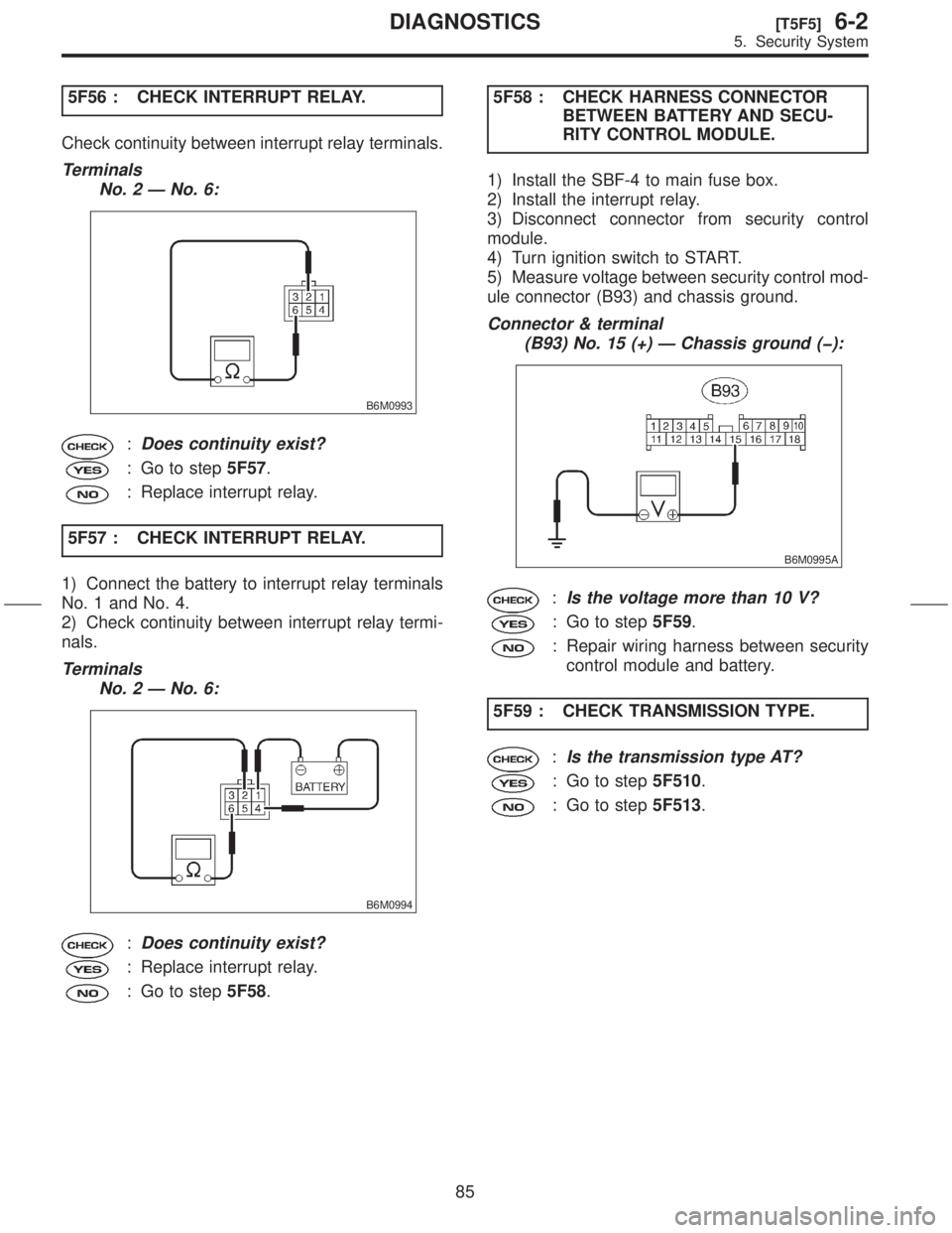
5F56 : CHECK INTERRUPT RELAY.
Check continuity between interrupt relay terminals.
Terminals
No. 2 Ð No. 6:
B6M0993
:Does continuity exist?
: Go to step5F57.
: Replace interrupt relay.
5F57 : CHECK INTERRUPT RELAY.
1) Connect the battery to interrupt relay terminals
No. 1 and No. 4.
2) Check continuity between interrupt relay termi-
nals.
Terminals
No. 2 Ð No. 6:
B6M0994
:Does continuity exist?
: Replace interrupt relay.
: Go to step5F58.5F58 : CHECK HARNESS CONNECTOR
BETWEEN BATTERY AND SECU-
RITY CONTROL MODULE.
1) Install the SBF-4 to main fuse box.
2) Install the interrupt relay.
3) Disconnect connector from security control
module.
4) Turn ignition switch to START.
5) Measure voltage between security control mod-
ule connector (B93) and chassis ground.
Connector & terminal
(B93) No. 15 (+) Ð Chassis ground (þ):
B6M0995A
:Is the voltage more than 10 V?
: Go to step5F59.
: Repair wiring harness between security
control module and battery.
5F59 : CHECK TRANSMISSION TYPE.
:Is the transmission type AT?
: Go to step5F510.
: Go to step5F513.
85
[T5F5]6-2DIAGNOSTICS
5. Security System
Page 208 of 345
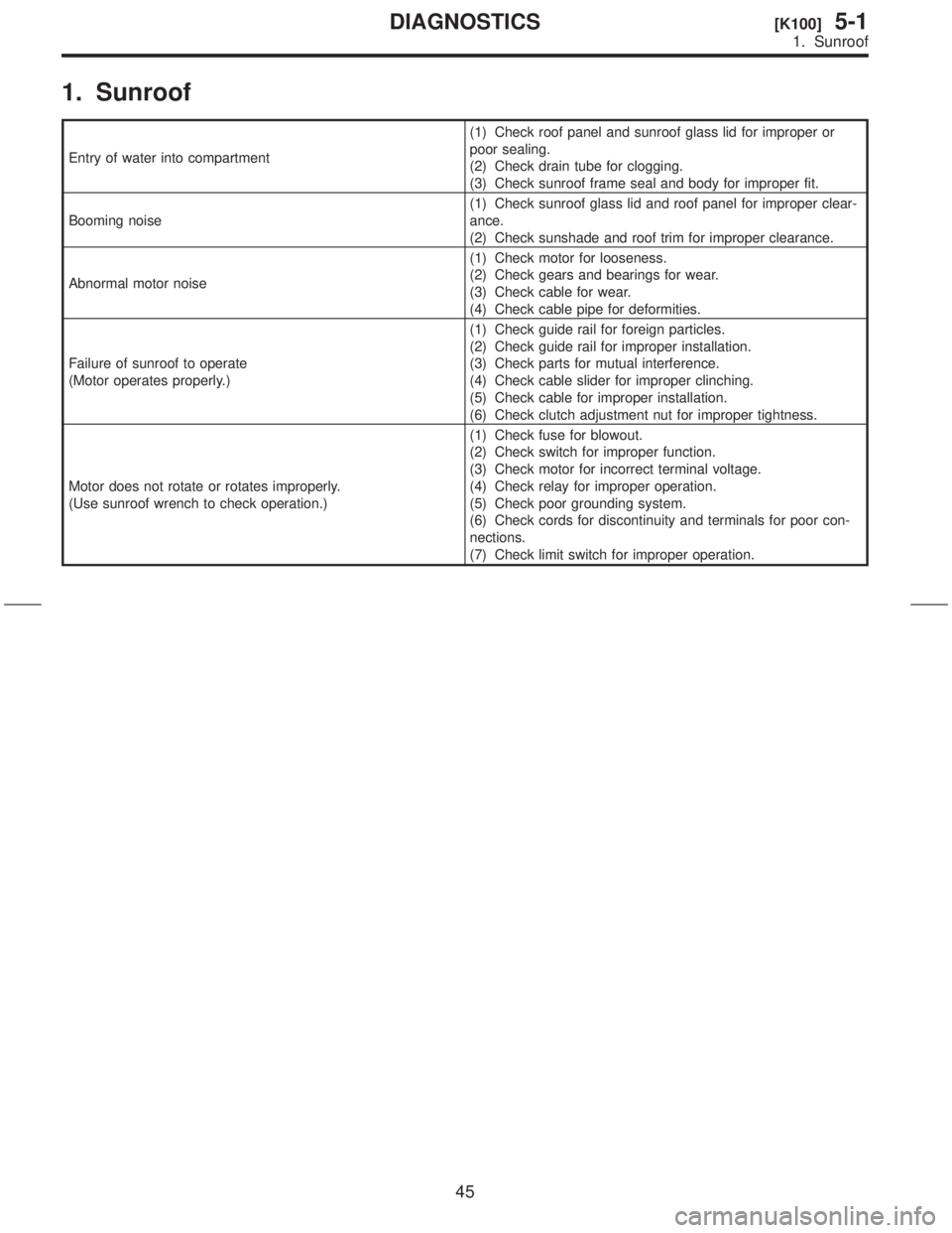
1. Sunroof
Entry of water into compartment(1) Check roof panel and sunroof glass lid for improper or
poor sealing.
(2) Check drain tube for clogging.
(3) Check sunroof frame seal and body for improper fit.
Booming noise(1) Check sunroof glass lid and roof panel for improper clear-
ance.
(2) Check sunshade and roof trim for improper clearance.
Abnormal motor noise(1) Check motor for looseness.
(2) Check gears and bearings for wear.
(3) Check cable for wear.
(4) Check cable pipe for deformities.
Failure of sunroof to operate
(Motor operates properly.)(1) Check guide rail for foreign particles.
(2) Check guide rail for improper installation.
(3) Check parts for mutual interference.
(4) Check cable slider for improper clinching.
(5) Check cable for improper installation.
(6) Check clutch adjustment nut for improper tightness.
Motor does not rotate or rotates improperly.
(Use sunroof wrench to check operation.)(1) Check fuse for blowout.
(2) Check switch for improper function.
(3) Check motor for incorrect terminal voltage.
(4) Check relay for improper operation.
(5) Check poor grounding system.
(6) Check cords for discontinuity and terminals for poor con-
nections.
(7) Check limit switch for improper operation.
45
[K100]5-1DIAGNOSTICS
1. Sunroof