Page 114 of 345
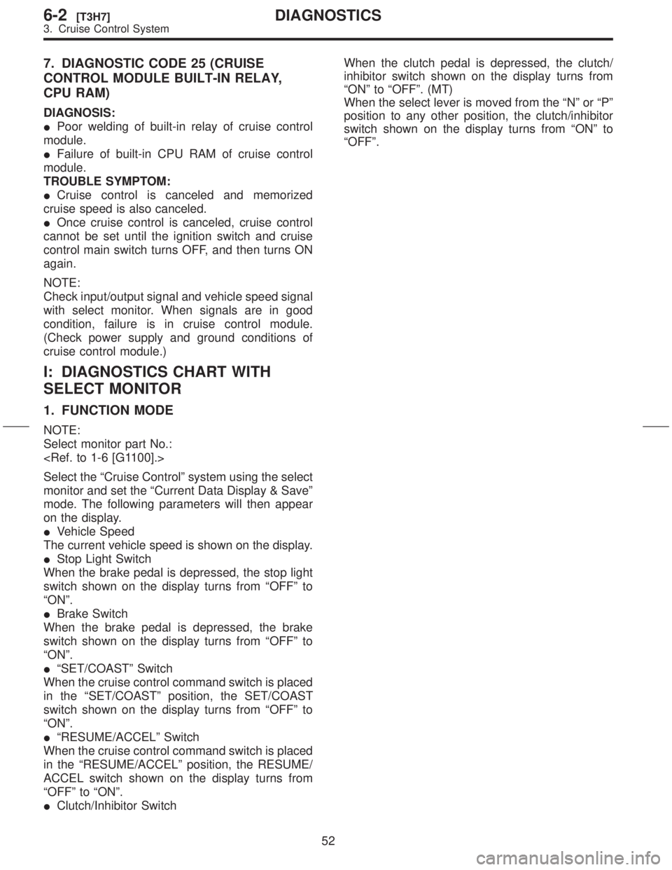
7. DIAGNOSTIC CODE 25 (CRUISE
CONTROL MODULE BUILT-IN RELAY,
CPU RAM)
DIAGNOSIS:
IPoor welding of built-in relay of cruise control
module.
IFailure of built-in CPU RAM of cruise control
module.
TROUBLE SYMPTOM:
ICruise control is canceled and memorized
cruise speed is also canceled.
IOnce cruise control is canceled, cruise control
cannot be set until the ignition switch and cruise
control main switch turns OFF, and then turns ON
again.
NOTE:
Check input/output signal and vehicle speed signal
with select monitor. When signals are in good
condition, failure is in cruise control module.
(Check power supply and ground conditions of
cruise control module.)
I: DIAGNOSTICS CHART WITH
SELECT MONITOR
1. FUNCTION MODE
NOTE:
Select monitor part No.:
Select the ªCruise Controlº system using the select
monitor and set the ªCurrent Data Display & Saveº
mode. The following parameters will then appear
on the display.
IVehicle Speed
The current vehicle speed is shown on the display.
IStop Light Switch
When the brake pedal is depressed, the stop light
switch shown on the display turns from ªOFFº to
ªONº.
IBrake Switch
When the brake pedal is depressed, the brake
switch shown on the display turns from ªOFFº to
ªONº.
IªSET/COASTº Switch
When the cruise control command switch is placed
in the ªSET/COASTº position, the SET/COAST
switch shown on the display turns from ªOFFº to
ªONº.
IªRESUME/ACCELº Switch
When the cruise control command switch is placed
in the ªRESUME/ACCELº position, the RESUME/
ACCEL switch shown on the display turns from
ªOFFº to ªONº.
IClutch/Inhibitor SwitchWhen the clutch pedal is depressed, the clutch/
inhibitor switch shown on the display turns from
ªONº to ªOFFº. (MT)
When the select lever is moved from the ªNº or ªPº
position to any other position, the clutch/inhibitor
switch shown on the display turns from ªONº to
ªOFFº.
52
6-2[T3H7]DIAGNOSTICS
3. Cruise Control System
Page 146 of 345
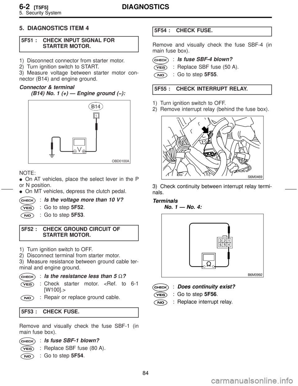
5. DIAGNOSTICS ITEM 4
5F51 : CHECK INPUT SIGNAL FOR
STARTER MOTOR.
1) Disconnect connector from starter motor.
2) Turn ignition switch to START.
3) Measure voltage between starter motor con-
nector (B14) and engine ground.
Connector & terminal
(B14) No. 1 (+) Ð Engine ground (þ):
OBD0100A
NOTE:
IOn AT vehicles, place the select lever in the P
or N position.
IOn MT vehicles, depress the clutch pedal.
:Is the voltage more than 10 V?
: Go to step5F52.
: Go to step5F53.
5F52 : CHECK GROUND CIRCUIT OF
STARTER MOTOR.
1) Turn ignition switch to OFF.
2) Disconnect terminal from starter motor.
3) Measure resistance between ground cable ter-
minal and engine ground.
:Is the resistance less than 5W?
: Check starter motor.
[W100].>
: Repair or replace ground cable.
5F53 : CHECK FUSE.
Remove and visually check the fuse SBF-1 (in
main fuse box).
:Is fuse SBF-1 blown?
: Replace SBF fuse (80 A).
: Go to step5F54.5F54 : CHECK FUSE.
Remove and visually check the fuse SBF-4 (in
main fuse box).
:Is fuse SBF-4 blown?
: Replace SBF fuse (50 A).
: Go to step5F55.
5F55 : CHECK INTERRUPT RELAY.
1) Turn ignition switch to OFF.
2) Remove interrupt relay (behind the fuse box).
S6M0469
3) Check continuity between interrupt relay termi-
nals.
Terminals
No. 1 Ð No. 4:
B6M0992
:Does continuity exist?
: Go to step5F56.
: Replace interrupt relay.
84
6-2[T5F5]DIAGNOSTICS
5. Security System
Page 149 of 345
5F514 : CHECK STARTER INTERLOCK
RELAY.
Check continuity between starter interlock relay
terminals.
Terminals
No. 1 Ð No. 4:
B6M1378
:Does continuity exist?
: Replace starter interlock relay.
: Go to step5F515.
5F515 : CHECK STARTER INTERLOCK
RELAY.
1) Connect the battery to starter interlock relay ter-
minals No. 3 and No. 2.
2) Check continuity between starter interlock relay
terminals.
Terminals
No. 1 Ð No. 4:
B6M1379
:Does continuity exist?
: Go to step5F516.
: Replace starter interlock relay.5F516 : CHECK CLUTCH SWITCH.
1) Install starter interlock relay.
2) Measure resistance between clutch switch con-
nector (B106) and (B107) terminals while depress-
ing the clutch pedal.
Connector & terminal
With cruise control
(B107) No. 1 Ð No. 2:
Without cruise control
(B106) No. 1 Ð No. 2:
B2M0518A
:Is the resistance less than 10W?
: Go to step5F517.
: Replace clutch switch.
87
[T5F5]6-2DIAGNOSTICS
5. Security System
Page 150 of 345
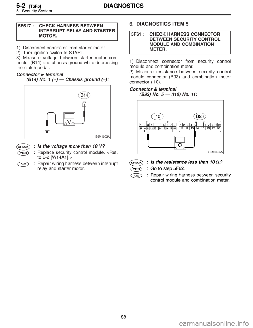
5F517 : CHECK HARNESS BETWEEN
INTERRUPT RELAY AND STARTER
MOTOR.
1) Disconnect connector from starter motor.
2) Turn ignition switch to START.
3) Measure voltage between starter motor con-
nector (B14) and chassis ground while depressing
the clutch pedal.
Connector & terminal
(B14) No. 1 (+) Ð Chassis ground (þ):
B6M1002A
:Is the voltage more than 10 V?
: Replace security control module.
to 6-2 [W14A1].>
: Repair wiring harness between interrupt
relay and starter motor.
6. DIAGNOSTICS ITEM 5
5F61 : CHECK HARNESS CONNECTOR
BETWEEN SECURITY CONTROL
MODULE AND COMBINATION
METER.
1) Disconnect connector from security control
module and combination meter.
2) Measure resistance between security control
module connector (B93) and combination meter
connector (i10).
Connector & terminal
(B93) No. 5 Ð (i10) No. 11:
S6M0465A
:Is the resistance less than 10W?
: Go to step5F62.
: Repair wiring harness between security
control module and combination meter.
88
6-2[T5F5]DIAGNOSTICS
5. Security System
Page 208 of 345
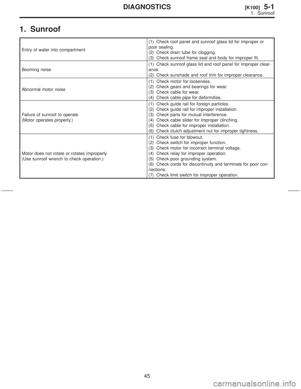
1. Sunroof
Entry of water into compartment(1) Check roof panel and sunroof glass lid for improper or
poor sealing.
(2) Check drain tube for clogging.
(3) Check sunroof frame seal and body for improper fit.
Booming noise(1) Check sunroof glass lid and roof panel for improper clear-
ance.
(2) Check sunshade and roof trim for improper clearance.
Abnormal motor noise(1) Check motor for looseness.
(2) Check gears and bearings for wear.
(3) Check cable for wear.
(4) Check cable pipe for deformities.
Failure of sunroof to operate
(Motor operates properly.)(1) Check guide rail for foreign particles.
(2) Check guide rail for improper installation.
(3) Check parts for mutual interference.
(4) Check cable slider for improper clinching.
(5) Check cable for improper installation.
(6) Check clutch adjustment nut for improper tightness.
Motor does not rotate or rotates improperly.
(Use sunroof wrench to check operation.)(1) Check fuse for blowout.
(2) Check switch for improper function.
(3) Check motor for incorrect terminal voltage.
(4) Check relay for improper operation.
(5) Check poor grounding system.
(6) Check cords for discontinuity and terminals for poor con-
nections.
(7) Check limit switch for improper operation.
45
[K100]5-1DIAGNOSTICS
1. Sunroof
Page 298 of 345

5) Remove packing A, three planetary gears,
packing B and plate.
CAUTION:
Record the position of packing A before remov-
ing.
S6M0397A
(A) Packing A
(B) Planetary gear
(C) Plate
(D) Packing B
6) Remove shaft assembly and overrunning clutch
as a unit.
CAUTION:
Record the direction of lever before removing.
S6M0398A
(A) Shaft ASSY
(B) Overrunning clutch
(C) Lever
7) Remove overrunning clutch from shaft assem-
bly as follows:
(1) Remove stopper from ring by lightly tapping
a fit tool placed on stopper.
(2) Remove ring, stopper and clutch from shaft.
S6M0399A
(A) Stopper
(B) Tool
(C) Ring
(D) Shaft
2. BRUSH HOLDER
Slightly open the metal fitting holding the insulating
plate to the brush holder. Remove the insulating
plate.
NOTE:
The brush and spring can be easily removed from
the brush holder at this time.
H6M0497C
(A) Brush holder
(B) Insulating plate
(C) Metal fitting
D: INSPECTION
1. ARMATURE
1) Check commutator for any sign of burns of
rough surfaces or stepped wear. If wear is of a
minor nature, correct it by using sand paper.
9
[W1D1]6-1SERVICE PROCEDURE
1. Starter
Page 300 of 345
2. YOKE
Make sure pole is set in position.
3. OVERRUNNING CLUTCH
Inspect teeth of pinion for wear and damage.
Replace if it is damaged. Rotate pinion in direction
of rotation (counterclockwise). It should rotate
smoothly. But in opposite direction, it should be
locked.
CAUTION:
Do not clean overrunning clutch with oil to pre-
vent grease from flowing out.
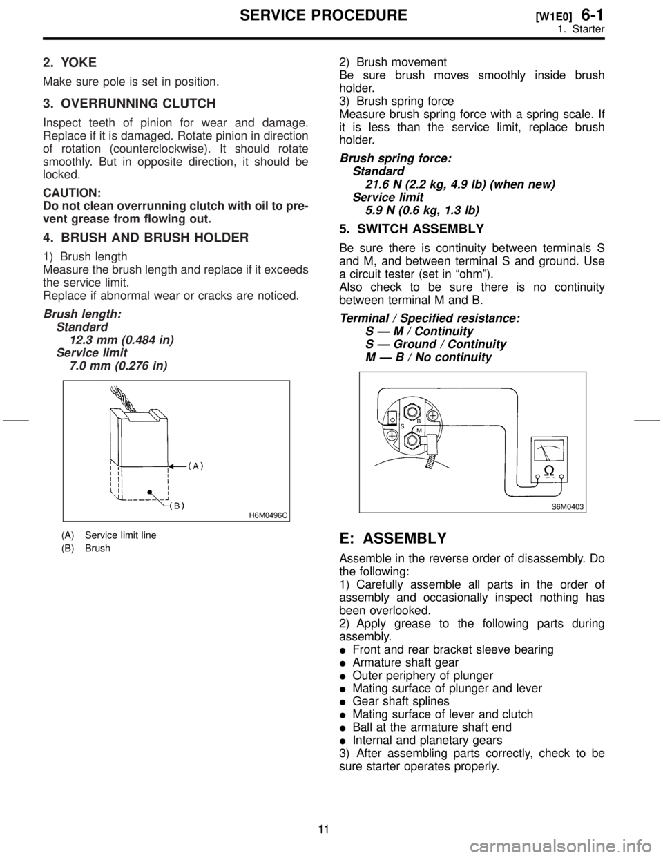
4. BRUSH AND BRUSH HOLDER
1) Brush length
Measure the brush length and replace if it exceeds
the service limit.
Replace if abnormal wear or cracks are noticed.
Brush length:
Standard
12.3 mm (0.484 in)
Service limit
7.0 mm (0.276 in)
H6M0496C
(A) Service limit line
(B) Brush
2) Brush movement
Be sure brush moves smoothly inside brush
holder.
3) Brush spring force
Measure brush spring force with a spring scale. If
it is less than the service limit, replace brush
holder.
Brush spring force:
Standard
21.6 N (2.2 kg, 4.9 lb) (when new)
Service limit
5.9 N (0.6 kg, 1.3 lb)
5. SWITCH ASSEMBLY
Be sure there is continuity between terminals S
and M, and between terminal S and ground. Use
a circuit tester (set in ªohmº).
Also check to be sure there is no continuity
between terminal M and B.
Terminal / Specified resistance:
SÐM/Continuity
S Ð Ground / Continuity
MÐB/Nocontinuity
S6M0403
E: ASSEMBLY
Assemble in the reverse order of disassembly. Do
the following:
1) Carefully assemble all parts in the order of
assembly and occasionally inspect nothing has
been overlooked.
2) Apply grease to the following parts during
assembly.
IFront and rear bracket sleeve bearing
IArmature shaft gear
IOuter periphery of plunger
IMating surface of plunger and lever
IGear shaft splines
IMating surface of lever and clutch
IBall at the armature shaft end
IInternal and planetary gears
3) After assembling parts correctly, check to be
sure starter operates properly.
11
[W1E0]6-1SERVICE PROCEDURE
1. Starter
Page 315 of 345
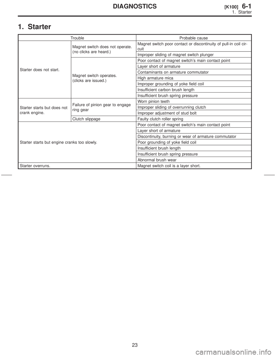
1. Starter
Trouble Probable cause
Starter does not start.Magnet switch does not operate.
(no clicks are heard.)Magnet switch poor contact or discontinuity of pull-in coil cir-
cuit
Improper sliding of magnet switch plunger
Magnet switch operates.
(clicks are issued.)Poor contact of magnet switch's main contact point
Layer short of armature
Contaminants on armature commutator
High armature mica
Improper grounding of yoke field coil
Insufficient carbon brush length
Insufficient brush spring pressure
Starter starts but does not
crank engine.Failure of pinion gear to engage
ring gearWorn pinion teeth
Improper sliding of overrunning clutch
Improper adjustment of stud bolt
Clutch slippage Faulty clutch roller spring
Starter starts but engine cranks too slowly.Poor contact of magnet switch's main contact point
Layer short of armature
Discontinuity, burning or wear of armature commutator
Poor grounding of yoke field coil
Insufficient brush length
Insufficient brush spring pressure
Abnormal brush wear
Starter overruns. Magnet switch coil is a layer short.
23
[K100]6-1DIAGNOSTICS
1. Starter