1999 NISSAN PICK-UP door lock
[x] Cancel search: door lockPage 560 of 666

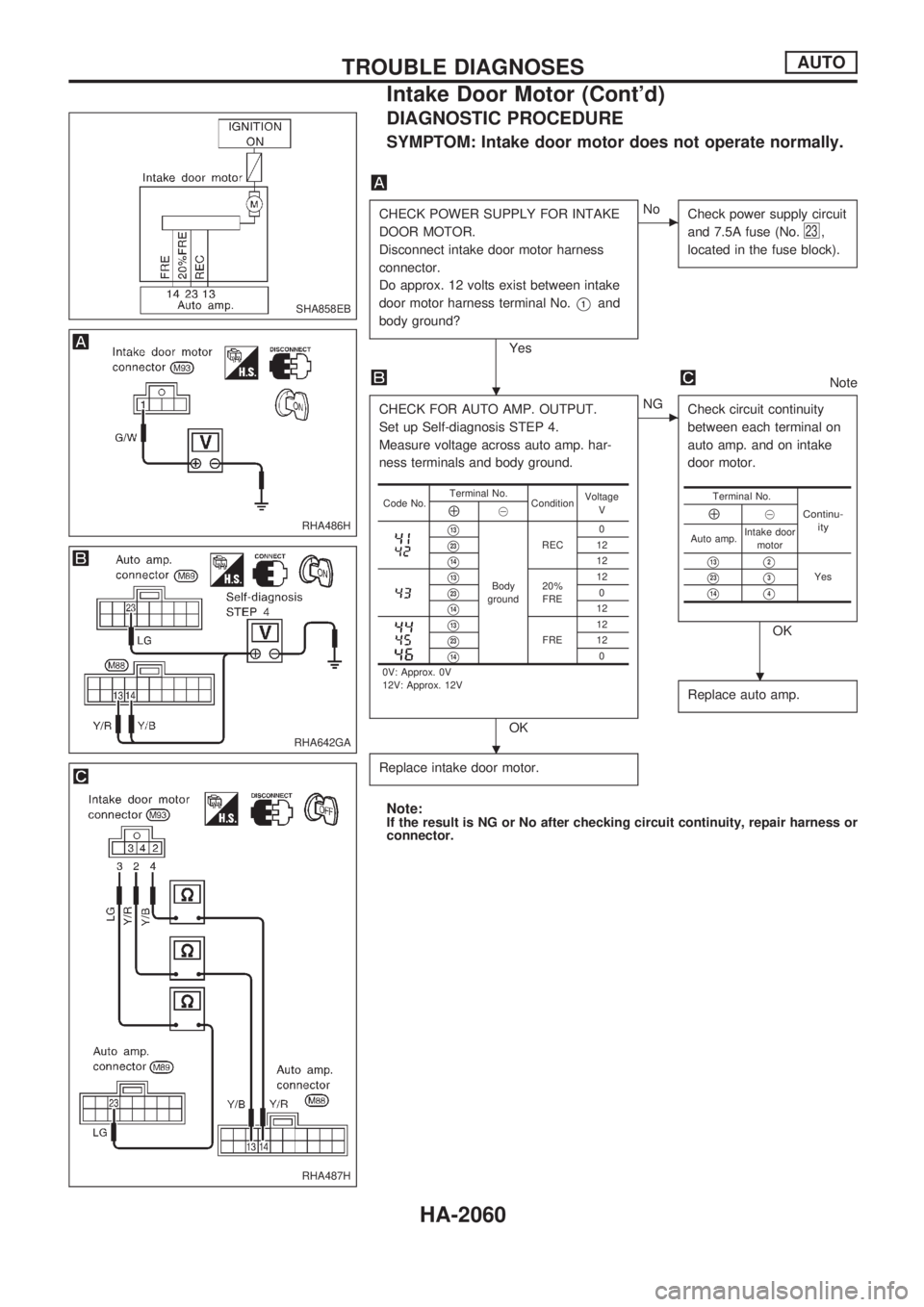
DIAGNOSTIC PROCEDURE
SYMPTOM: Intake door motor does not operate normally.
CHECK POWER SUPPLY FOR INTAKE
DOOR MOTOR.
Disconnect intake door motor harness
connector.
Do approx. 12 volts exist between intake
door motor harness terminal No.
V1and
body ground?
Yes
cNo
Check power supply circuit
and 7.5A fuse (No.
23,
located in the fuse block).
Note
CHECK FOR AUTO AMP. OUTPUT.
Set up Self-diagnosis STEP 4.
Measure voltage across auto amp. har-
ness terminals and body ground.
OK
cNG
Check circuit continuity
between each terminal on
auto amp. and on intake
door motor.
OK
Replace auto amp.
Replace intake door motor.
Note:If the result is NG or No after checking circuit continuity, repair harness or
connector.
Code No.Terminal No.
ConditionVoltage
VÅ@
V13
Body
groundREC0
V2312
V1412
V1320%
FRE12V230
V1412
V13
FRE12V2312
V140
0V: Approx. 0V
12V: Approx. 12V
Terminal No.
Continu-
ityÅ@
Auto amp.Intake door
motor
V13V2
YesV23V3
V14V4
SHA858EB
RHA486H
RHA642GA
RHA487H
.
.
.
TROUBLE DIAGNOSESAUTO
Intake Door Motor (Cont'd)
HA-2060
Page 590 of 666

A
A/C harness layout (auto A/C)..................HA-2026
A/C operational check...............................HA-2041
A/C relay .........................................HA-2021, 2073
A/C self-diagnoses (auto A/C) ..................HA-2034
A/C switch .................................................HA-2021
A/C system description (auto A/C) ...........HA-2023
A/C trouble diagnoses (manual A/C) ........HA-2003
A/C, A - Wiring diagram............................HA-2028
A/C, M - Wiring diagram ...........................HA-2005
AAC/V - Wiring diagram ...........................EC-2011
Air bag.......................................................RS-2004
Air bag disposal ........................................RS-2012
Air flow meter - See Mass air flow
sensor....................................................EC-2008
Air mix door control linkage
adjustment .............................................HA-2057
Air mix door motor ....................................HA-2057
Alternator ...................................................EL-2016
Ambient sensor .........................................HA-2080
Antenna .....................................................EL-2103
Anti-lock brake system - Wiring
diagram .......................................BR-2004, 2007
Aspirator motor .........................................HA-2084
Audio and A/C control removal and
installation - See Instrument panel........BT-2004
Automatic amplifier .........................HA-2032, 2045
Auxiliary air control (AAC) valve ...............EC-2011
B
Back-up lamp.............................................EL-2035
Back-up lamp switch (M/T) .......................MT-2002
Baulk ring (M/T) ........................................MT-2003
C
Camshaft position sensor (CMPS) ...........EC-2007
Center bearing assembly (propeller
shaft) .....................................................PD-2006
CHARGE - Wiring diagram .......................EL-2013
Charging system........................................EL-2013
CIGAR - Wiring diagram ...........................EL-2094
Cigarette lighter .........................................EL-2094
Clock ..........................................................EL-2095
CLOCK - Wiring diagram ..........................EL-2095
CMPS - Wiring diagram ............................EC-2007
Collision diagnosis ....................................RS-2039
Combination meter ....................................EL-2049
Combination meter removal and instal-
lation - See Instrument panel ................BT-2004
Combination switch ...................................EL-2017
Control units (terminal arrangement) ........EL-2176
Cooling fan control system........................LC-2002
Counter gear (M/T) ...................................MT-2003
Coupling sleeve (M/T) ..............................MT-2003Crank angle sensor built into distribu-
tor - See Camshaft position sensor ......EC-2007
Crankshaft position sensor (POS) ............EC-2007
Crankshaft position sensor (REF) ............EC-2007
Cylinder head ...........................................EM-2003
D
Daytime light system .................................EL-2022
DEF - Wiring diagram................................EL-2096
Diagnosis sensor unit ...............................RS-2007
Differential carrier assembly .....................PD-2008
Dim-dip lamp system .................................EL-2025
Dimensions.................................................GI-2007
Door, front .................................................BT-2003
E
ECCS relay ...............................................EC-2005
EGR - Wiring diagram ..............................EC-2027
EGRC/V - Wiring diagram ........................EC-2013
Engine control circuit diagram ..................EC-2004
Engine outer component parts .................EM-2002
EVAP canister purge control solenoid
valve ......................................................EC-2013
F
F/HEAT - Wiring diagram .........................EC-2033
F/PUMP - Wiring diagram.........................EC-2015
Fan control amp. .......................................HA-2064
Fan switch .................................................HA-2021
FICD - Wiring diagram....................EC-2018, 2034
Fog lamp, rear ...........................................EL-2036
Fork rod (M/T)...........................................MT-2006
Front door ..................................................BT-2003
Front passenger air bag ...........................RS-2004
Front suspension .......................................FA-2002
Front wiper.................................................EL-2086
Fuel pump .................................................EC-2015
Fuel pump relay ........................................EC-2015
Fuse block .................................................EL-2175
G
Gauges ......................................................EL-2049
Gear components (M/T) ...........................MT-2003
Ground clearance.......................................GI-2007
H
H/AIM - Wiring diagram .............................EL-2028
H/LAMP - Wiring diagram .........................EL-2018
H02S - Wiring diagram .............................EC-2010
ALPHABETICAL INDEX
IDX-2002
Page 634 of 666

Disposal of Air Bag Module
lBefore disposing of air bag module, or vehicles equipped with such a system, deploy the system. If such
a system has already been deployed due to an accident, dispose of them as indicated in ``DISPOSING
OF AIR BAG MODULE'' (RS-2014).
lWhen deploying the air bag module, always use the Special Service Tool; Deployment tool KV99106400.
lWhen deploying the air bag module, stand at least 5 m (16 ft) away from the deployment component.
lWhen deploying air bag module, a fairly loud noise is made, followed by smoke being released. The
smoke is not poisonous, however, be careful not to inhale smoke since it irritates the throat and can
cause choking.
lAlways activate one air bag module at a time.
lDue to heat, leave air bag module unattended for more than 30 minutes after deployment.
lBe sure to wear gloves when handling a deployed air bag module.
lNever apply water to the deployed air bag module.
lWash your hands clean after finishing work.
lPlace the vehicle outdoors with an open space of at least 6 m (20 ft) on all sides when deploying air
bag module while mounted in vehicle.
lUse a voltmeter to make sure the vehicle battery is fully charged.
lDo not dispose of the air bag module un-deployed.
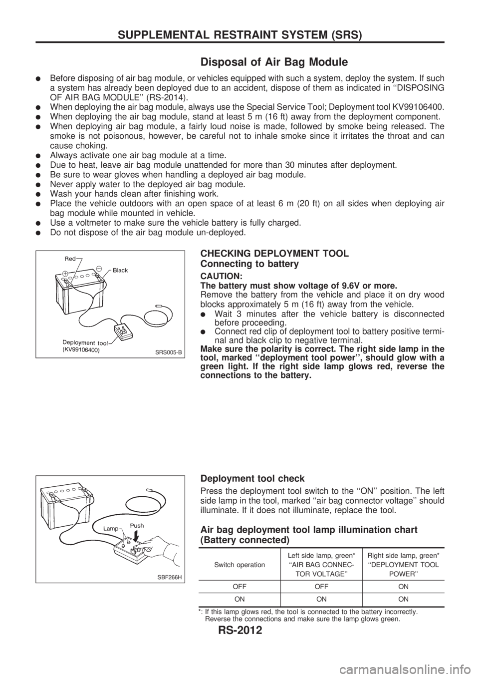
CHECKING DEPLOYMENT TOOL
Connecting to battery
CAUTION:
The battery must show voltage of 9.6V or more.
Remove the battery from the vehicle and place it on dry wood
blocks approximately 5 m (16 ft) away from the vehicle.
lWait 3 minutes after the vehicle battery is disconnected
before proceeding.
lConnect red clip of deployment tool to battery positive termi-
nal and black clip to negative terminal.
Make sure the polarity is correct. The right side lamp in the
tool, marked ``deployment tool power'', should glow with a
green light. If the right side lamp glows red, reverse the
connections to the battery.
Deployment tool check
Press the deployment tool switch to the ``ON'' position. The left
side lamp in the tool, marked ``air bag connector voltage'' should
illuminate. If it does not illuminate, replace the tool.
Air bag deployment tool lamp illumination chart
(Battery connected)
Switch operationLeft side lamp, green*
``AIR BAG CONNEC-
TOR VOLTAGE''Right side lamp, green*
``DEPLOYMENT TOOL
POWER''
OFF OFF ON
ON ON ON
*: If this lamp glows red, the tool is connected to the battery incorrectly.
Reverse the connections and make sure the lamp glows green.
SRS005-B
SBF266H
SUPPLEMENTAL RESTRAINT SYSTEM (SRS)
RS-2012