1999 NISSAN PICK-UP diagram
[x] Cancel search: diagramPage 530 of 666
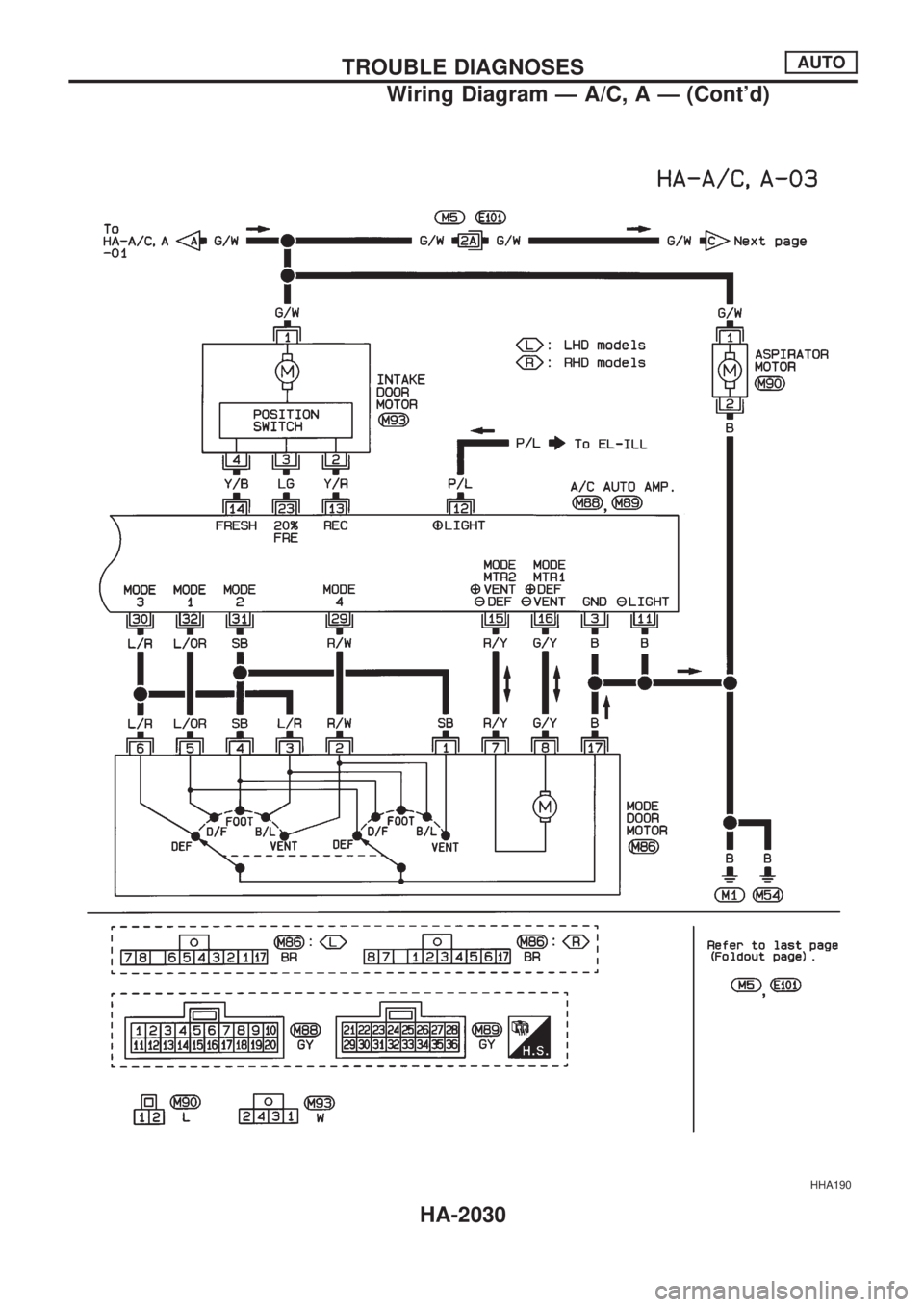
HHA190
TROUBLE DIAGNOSESAUTO
Wiring Diagram Ð A/C, A Ð (Cont'd)
HA-2030
Page 531 of 666
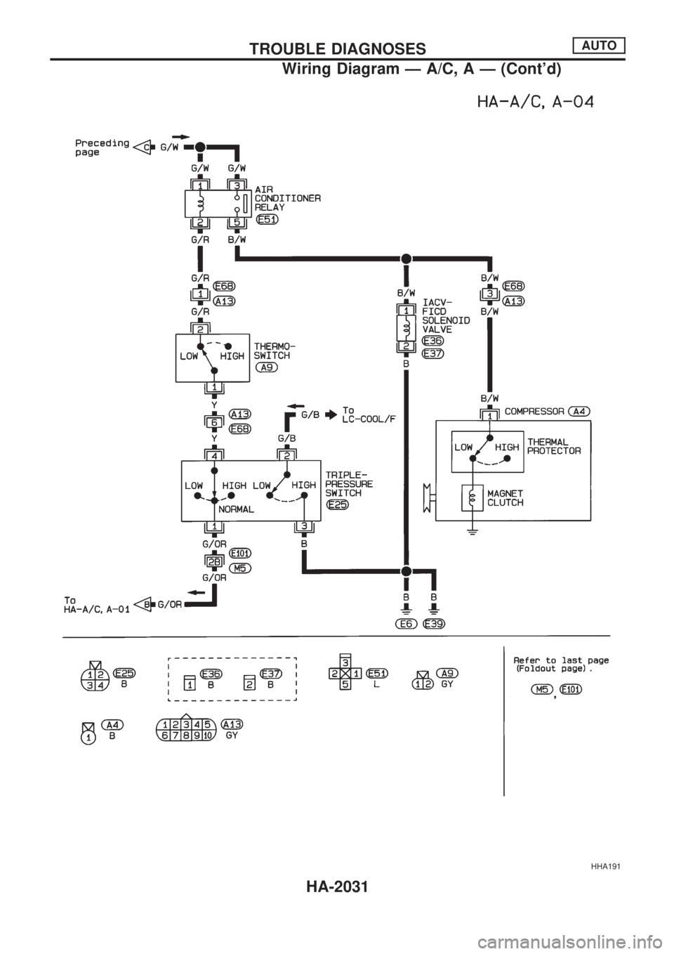
HHA191
TROUBLE DIAGNOSESAUTO
Wiring Diagram Ð A/C, A Ð (Cont'd)
HA-2031
Page 546 of 666
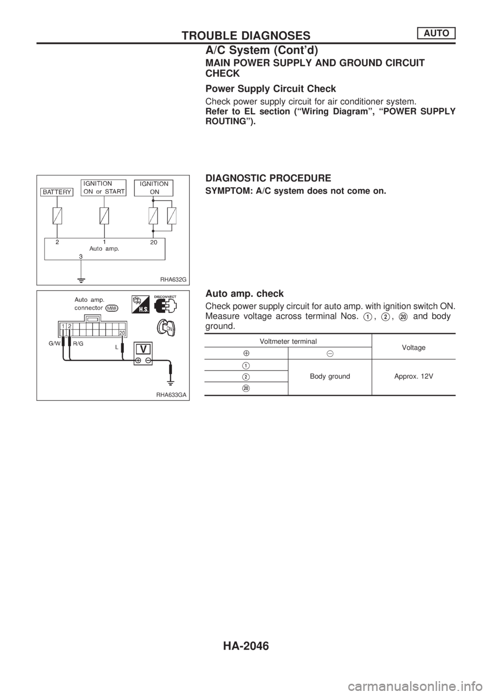
MAIN POWER SUPPLY AND GROUND CIRCUIT
CHECK
Power Supply Circuit Check
Check power supply circuit for air conditioner system.
Refer to EL section (ªWiring Diagramº, ªPOWER SUPPLY
ROUTINGº).
DIAGNOSTIC PROCEDURE
SYMPTOM: A/C system does not come on.
Auto amp. check
Check power supply circuit for auto amp. with ignition switch ON.
Measure voltage across terminal Nos.
V1,V2,V20and body
ground.
Voltmeter terminal
Voltage
Å@
V1
Body ground Approx. 12VV2
V20
RHA632G
RHA633GA
TROUBLE DIAGNOSESAUTO
A/C System (Cont'd)
HA-2046
Page 566 of 666
VA
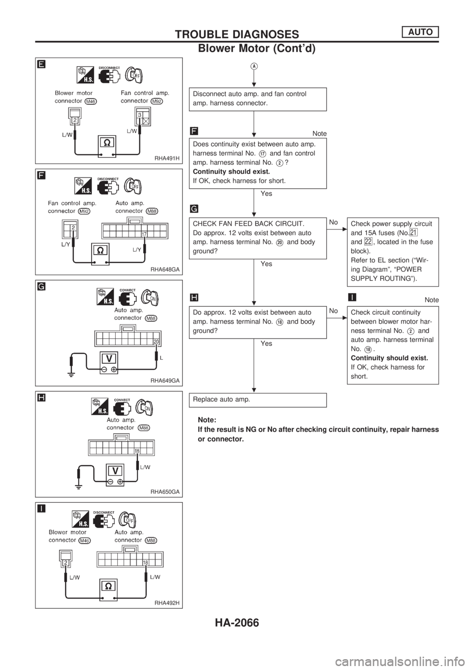
Disconnect auto amp. and fan control
amp. harness connector.
Note
Does continuity exist between auto amp.
harness terminal No.
V17and fan control
amp. harness terminal No.
V2?
Continuity should exist.
If OK, check harness for short.
Yes
CHECK FAN FEED BACK CIRCUIT.
Do approx. 12 volts exist between auto
amp. harness terminal No.
V20and body
ground?
Yes
cNo
Check power supply circuit
and 15A fuses (No.
21
and22, located in the fuse
block).
Refer to EL section (ªWir-
ing Diagramº, ªPOWER
SUPPLY ROUTINGº).
Note
Do approx. 12 volts exist between auto
amp. harness terminal No.
V18and body
ground?
Yes
cNo
Check circuit continuity
between blower motor har-
ness terminal No.
V2and
auto amp. harness terminal
No.
V18.
Continuity should exist.
If OK, check harness for
short.
Replace auto amp.
Note:
If the result is NG or No after checking circuit continuity, repair harness
or connector.
RHA491H
RHA648GA
RHA649GA
RHA650GA
RHA492H
.
.
.
.
.
TROUBLE DIAGNOSESAUTO
Blower Motor (Cont'd)
HA-2066
Page 570 of 666
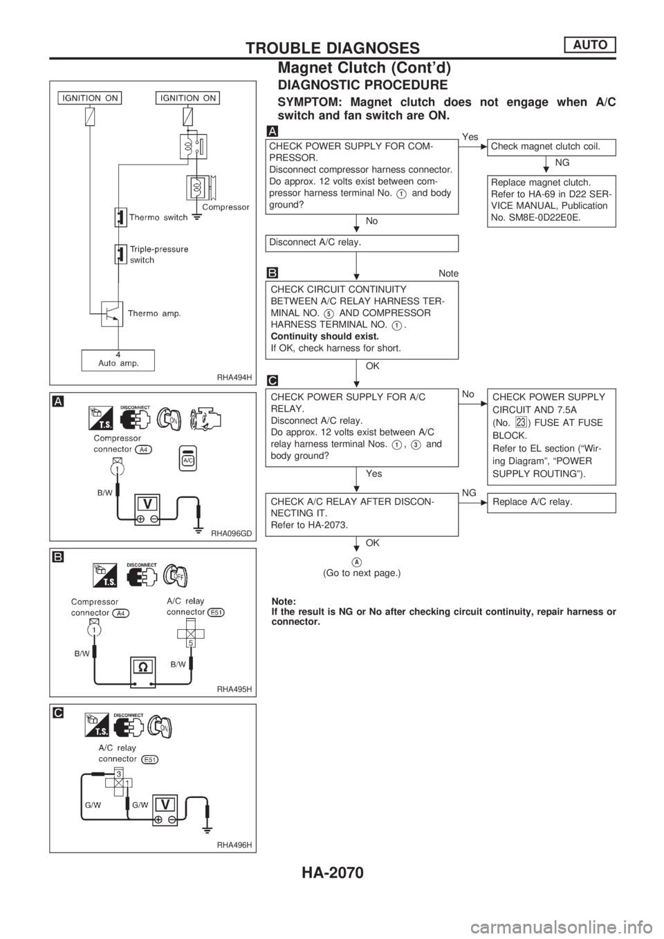
DIAGNOSTIC PROCEDURE
SYMPTOM: Magnet clutch does not engage when A/C
switch and fan switch are ON.
CHECK POWER SUPPLY FOR COM-
PRESSOR.
Disconnect compressor harness connector.
Do approx. 12 volts exist between com-
pressor harness terminal No.
V1and body
ground?
No
cYes
Check magnet clutch coil.
NG
Replace magnet clutch.
Refer to HA-69 in D22 SER-
VICE MANUAL, Publication
No. SM8E-0D22E0E.
Disconnect A/C relay.
Note
CHECK CIRCUIT CONTINUITY
BETWEEN A/C RELAY HARNESS TER-
MINAL NO.
V5AND COMPRESSOR
HARNESS TERMINAL NO.
V1.
Continuity should exist.
If OK, check harness for short.
OK
CHECK POWER SUPPLY FOR A/C
RELAY.
Disconnect A/C relay.
Do approx. 12 volts exist between A/C
relay harness terminal Nos.
V1,V3and
body ground?
Yes
cNo
CHECK POWER SUPPLY
CIRCUIT AND 7.5A
(No.
23) FUSE AT FUSE
BLOCK.
Refer to EL section (ªWir-
ing Diagramº, ªPOWER
SUPPLY ROUTINGº).
CHECK A/C RELAY AFTER DISCON-
NECTING IT.
Refer to HA-2073.
OK
cNG
Replace A/C relay.
VA
(Go to next page.)
Note:
If the result is NG or No after checking circuit continuity, repair harness or
connector.
RHA494H
RHA096GD
RHA495H
RHA496H
.
.
.
.
.
.
TROUBLE DIAGNOSESAUTO
Magnet Clutch (Cont'd)
HA-2070
Page 571 of 666
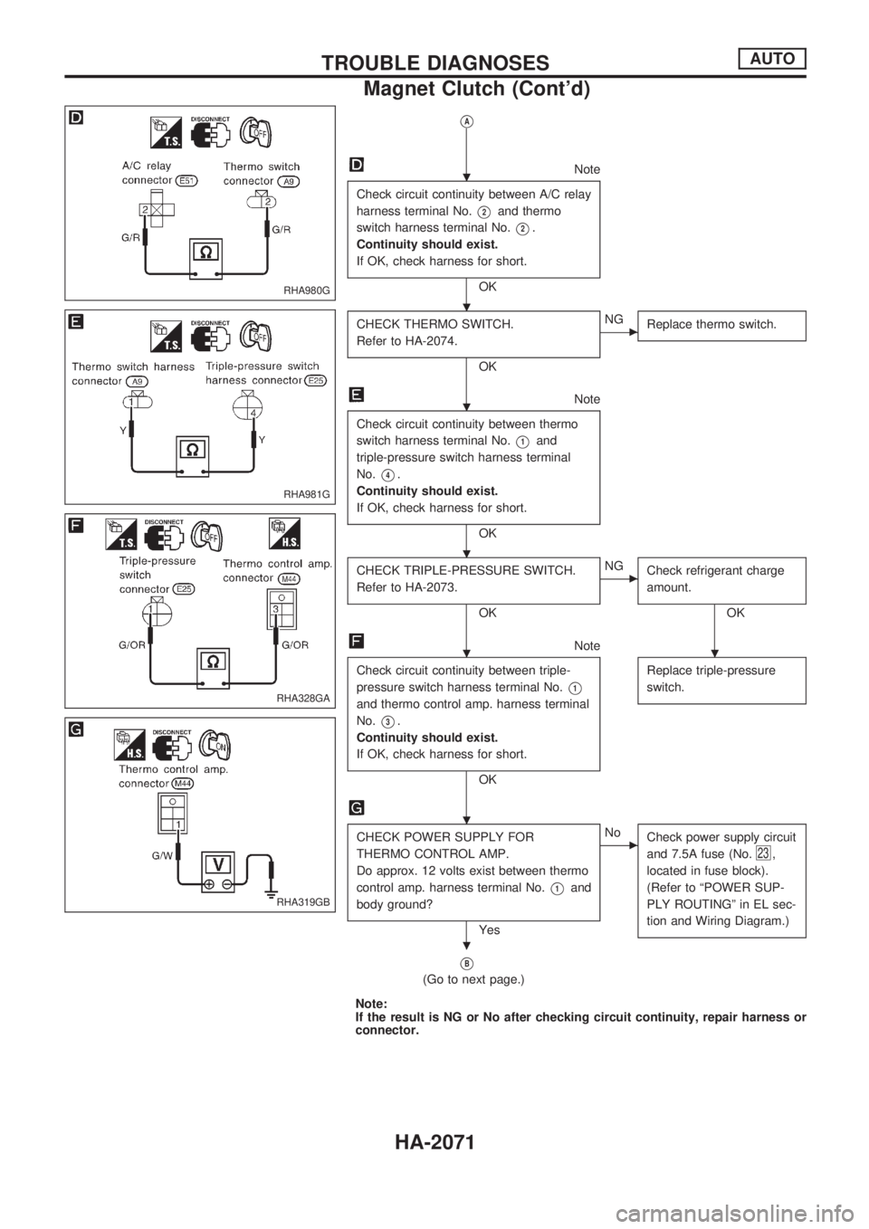
VA
Note
Check circuit continuity between A/C relay
harness terminal No.
V2and thermo
switch harness terminal No.
V2.
Continuity should exist.
If OK, check harness for short.
OK
CHECK THERMO SWITCH.
Refer to HA-2074.
OK
cNG
Replace thermo switch.
Note
Check circuit continuity between thermo
switch harness terminal No.
V1and
triple-pressure switch harness terminal
No.
V4.
Continuity should exist.
If OK, check harness for short.
OK
CHECK TRIPLE-PRESSURE SWITCH.
Refer to HA-2073.
OK
cNG
Check refrigerant charge
amount.
OK
Note
Check circuit continuity between triple-
pressure switch harness terminal No.
V1
and thermo control amp. harness terminal
No.
V3.
Continuity should exist.
If OK, check harness for short.
OKReplace triple-pressure
switch.
CHECK POWER SUPPLY FOR
THERMO CONTROL AMP.
Do approx. 12 volts exist between thermo
control amp. harness terminal No.
V1and
body ground?
Yes
cNo
Check power supply circuit
and 7.5A fuse (No.
23,
located in fuse block).
(Refer to ªPOWER SUP-
PLY ROUTINGº in EL sec-
tion and Wiring Diagram.)
VB
(Go to next page.)
Note:
If the result is NG or No after checking circuit continuity, repair harness or
connector.
RHA980G
RHA981G
RHA328GA
RHA319GB
.
.
.
.
..
.
.
TROUBLE DIAGNOSESAUTO
Magnet Clutch (Cont'd)
HA-2071
Page 590 of 666
A
A/C harness layout (auto A/C)..................HA-2026
A/C operational check...............................HA-2041
A/C relay .........................................HA-2021, 2073
A/C self-diagnoses (auto A/C) ..................HA-2034
A/C switch .................................................HA-2021
A/C system description (auto A/C) ...........HA-2023
A/C trouble diagnoses (manual A/C) ........HA-2003
A/C, A - Wiring diagram............................HA-2028
A/C, M - Wiring diagram ...........................HA-2005
AAC/V - Wiring diagram ...........................EC-2011
Air bag.......................................................RS-2004
Air bag disposal ........................................RS-2012
Air flow meter - See Mass air flow
sensor....................................................EC-2008
Air mix door control linkage
adjustment .............................................HA-2057
Air mix door motor ....................................HA-2057
Alternator ...................................................EL-2016
Ambient sensor .........................................HA-2080
Antenna .....................................................EL-2103
Anti-lock brake system - Wiring
diagram .......................................BR-2004, 2007
Aspirator motor .........................................HA-2084
Audio and A/C control removal and
installation - See Instrument panel........BT-2004
Automatic amplifier .........................HA-2032, 2045
Auxiliary air control (AAC) valve ...............EC-2011
B
Back-up lamp.............................................EL-2035
Back-up lamp switch (M/T) .......................MT-2002
Baulk ring (M/T) ........................................MT-2003
C
Camshaft position sensor (CMPS) ...........EC-2007
Center bearing assembly (propeller
shaft) .....................................................PD-2006
CHARGE - Wiring diagram .......................EL-2013
Charging system........................................EL-2013
CIGAR - Wiring diagram ...........................EL-2094
Cigarette lighter .........................................EL-2094
Clock ..........................................................EL-2095
CLOCK - Wiring diagram ..........................EL-2095
CMPS - Wiring diagram ............................EC-2007
Collision diagnosis ....................................RS-2039
Combination meter ....................................EL-2049
Combination meter removal and instal-
lation - See Instrument panel ................BT-2004
Combination switch ...................................EL-2017
Control units (terminal arrangement) ........EL-2176
Cooling fan control system........................LC-2002
Counter gear (M/T) ...................................MT-2003
Coupling sleeve (M/T) ..............................MT-2003Crank angle sensor built into distribu-
tor - See Camshaft position sensor ......EC-2007
Crankshaft position sensor (POS) ............EC-2007
Crankshaft position sensor (REF) ............EC-2007
Cylinder head ...........................................EM-2003
D
Daytime light system .................................EL-2022
DEF - Wiring diagram................................EL-2096
Diagnosis sensor unit ...............................RS-2007
Differential carrier assembly .....................PD-2008
Dim-dip lamp system .................................EL-2025
Dimensions.................................................GI-2007
Door, front .................................................BT-2003
E
ECCS relay ...............................................EC-2005
EGR - Wiring diagram ..............................EC-2027
EGRC/V - Wiring diagram ........................EC-2013
Engine control circuit diagram ..................EC-2004
Engine outer component parts .................EM-2002
EVAP canister purge control solenoid
valve ......................................................EC-2013
F
F/HEAT - Wiring diagram .........................EC-2033
F/PUMP - Wiring diagram.........................EC-2015
Fan control amp. .......................................HA-2064
Fan switch .................................................HA-2021
FICD - Wiring diagram....................EC-2018, 2034
Fog lamp, rear ...........................................EL-2036
Fork rod (M/T)...........................................MT-2006
Front door ..................................................BT-2003
Front passenger air bag ...........................RS-2004
Front suspension .......................................FA-2002
Front wiper.................................................EL-2086
Fuel pump .................................................EC-2015
Fuel pump relay ........................................EC-2015
Fuse block .................................................EL-2175
G
Gauges ......................................................EL-2049
Gear components (M/T) ...........................MT-2003
Ground clearance.......................................GI-2007
H
H/AIM - Wiring diagram .............................EL-2028
H/LAMP - Wiring diagram .........................EL-2018
H02S - Wiring diagram .............................EC-2010
ALPHABETICAL INDEX
IDX-2002
Page 591 of 666
Harness layout...........................................EL-2146
Hazard warning lamp ................................EL-2038
Headlamp ..................................................EL-2018
Headlamp washer......................................EL-2092
Headlining - See Roof trim........................BT-2010
Heated oxygen sensor (HO2S) ................EC-2010
Heated seat ...............................................EL-2106
HEATER - Wiring diagram........................HA-2003
Height (Dimensions)...................................GI-2007
HLC - Wiring diagram................................EL-2092
Horn ...........................................................EL-2093
HORN - Wiring diagram ............................EL-2093
HSEAT - Wiring diagram ...........................EL-2106
I
IACV-AAC valve........................................EC-2011
ILL - Wiring diagram ..................................EL-2043
Illumination.................................................EL-2043
In vehicle sensor .......................................HA-2082
Instrument panel........................................BT-2004
INT/L - Wiring diagram ..............................EL-2048
Intake door control linkage
adjustment .............................................HA-2061
Intake sensor ............................................HA-2088
Interior .......................................................BT-2007
Interior lamp...............................................EL-2047
J
Jump seat ..................................................BT-2012
K
Keyless entry system - See
Multi-remote control system ..................EL-2129
L
Length (Dimensions) ..................................GI-2007
License lamp .............................................EL-2030
Location of electrical units .........................EL-2143
Lubricants .................................................MA-2003
M
MAFS - Wiring diagram ............................EC-2008
MAIN - Wiring diagram .............................EC-2005
Main drive gear (M/T) ...............................MT-2003
Mainshaft (M/T).........................................MT-2003
Mass air flow sensor (MAFS) ...................EC-2008
Meter..........................................................EL-2049
METER - Wiring diagram ..........................EL-2052
MIL & Data link connectors circuit ............EC-2019Mode door control linkage adjustment .....HA-2051
Mode door motor ......................................HA-2051
MULTI - Wiring diagram ............................EL-2131
Multi-remote control system ......................EL-2129
N
NATS - Wiring diagram .............................EL-2140
Neutral position switch ..............................EC-2012
O
Oil change (capacity)................................MA-2003
P
P/ANT - Wiring diagram ............................EL-2103
Park/neutral position switch (M/T) ............MT-2002
Parking lamp..............................................EL-2030
PGC/V - Wiring diagram ...........................EC-2013
PNP/SW - Wiring diagram ........................EC-2012
POWER - Wiring diagram .........................EL-2005
Power door mirror......................................EL-2104
Power supply routing .................................EL-2004
Power window ...........................................EL-2108
Propeller shaft ...........................................PD-2004
PST/SW - Wiring diagram ........................EC-2016
R
R/FOG - Wiring diagram ...........................EL-2036
Rear fog lamp ............................................EL-2036
Rear window defogger ..............................EL-2096
Reverse idler shaft (M/T) ..........................MT-2003
Reverse lamp switch (M/T) - See
Back-up lamp switch (M/T) ...................MT-2002
Reverse main gear (M/T) .........................MT-2003
Road wheel size.........................................GI-2007
Roof trim ....................................................BT-2010
Room lamp ................................................EL-2047
ROOM/L - Wiring diagram.........................EL-2047
S
S/SIG - Wiring diagram.............................EC-2014
Seat belt pre-tensioner .............................RS-2004
Seat belt pre-tensioner disposal ...............RS-2012
Shift control components (M/T) ................MT-2006
Shift fork (M/T) ..........................................MT-2006
Shift lever ..................................................MT-2006
Side trim ....................................................BT-2007
SMJ (super multiple junction) ....................EL-2173
Spiral cable ...............................................RS-2008
Spot lamp ..................................................EL-2048
ALPHABETICAL INDEX
IDX-2003