1999 NISSAN PICK-UP steering wheel
[x] Cancel search: steering wheelPage 629 of 666
lRemove air bag module from steering wheel, instrument
panel or seat back. Check harness cover and connectors for
damage, terminals for deformities, and harness for binding.
lInstall driver air bag module to steering wheel to check fit or
alignment with the wheel.
lCheck steering wheel for excessive free play.
lInstall passenger air bag module to instrument panel to
check fit or alignment with the instrument panel.
(3) Spiral cable
lCheck spiral cable for dents, cracks, or deformities.
lCheck connectors and protective tape for damage.
lCheck steering wheel for noise, binding or heavy operation.
(4) Main harness and air bag harness
lCheck connectors for poor connections, damage, and termi-
nals for deformities.
lCheck harnesses for binding, chafing or cut.
CAUTION:
Replace previously used special bolts and ground bolt with
new ones.
Removal and Installation Ð Diagnosis
Sensor Unit
CAUTION:
lBefore servicing SRS, turn the ignition switch off, disconnect both battery cables and wait at least
3 minutes.
lDo not use old special bolts and nuts coated with bonding agent after removal; replace with new
ones.
lCheck diagnosis sensor unit for proper installation.
lCheck diagnosis sensor unit to ensure it is free of deformities, dents, cracks or rust. If it shows
any visible signs of damage, replace it with a new one.
lCheck diagnosis sensor unit brackets to ensure they are free of deformities and rust.
lAfter replacement of diagnosis sensor unit, check SRS function and perform self-diagnosis for
SRS. Refer to ``Self-diagnosis'' for details. (RS-2025)
lDo not attempt to disassemble diagnosis sensor unit.
lReplace diagnosis sensor unit and if it has been dropped or sustained an impact.
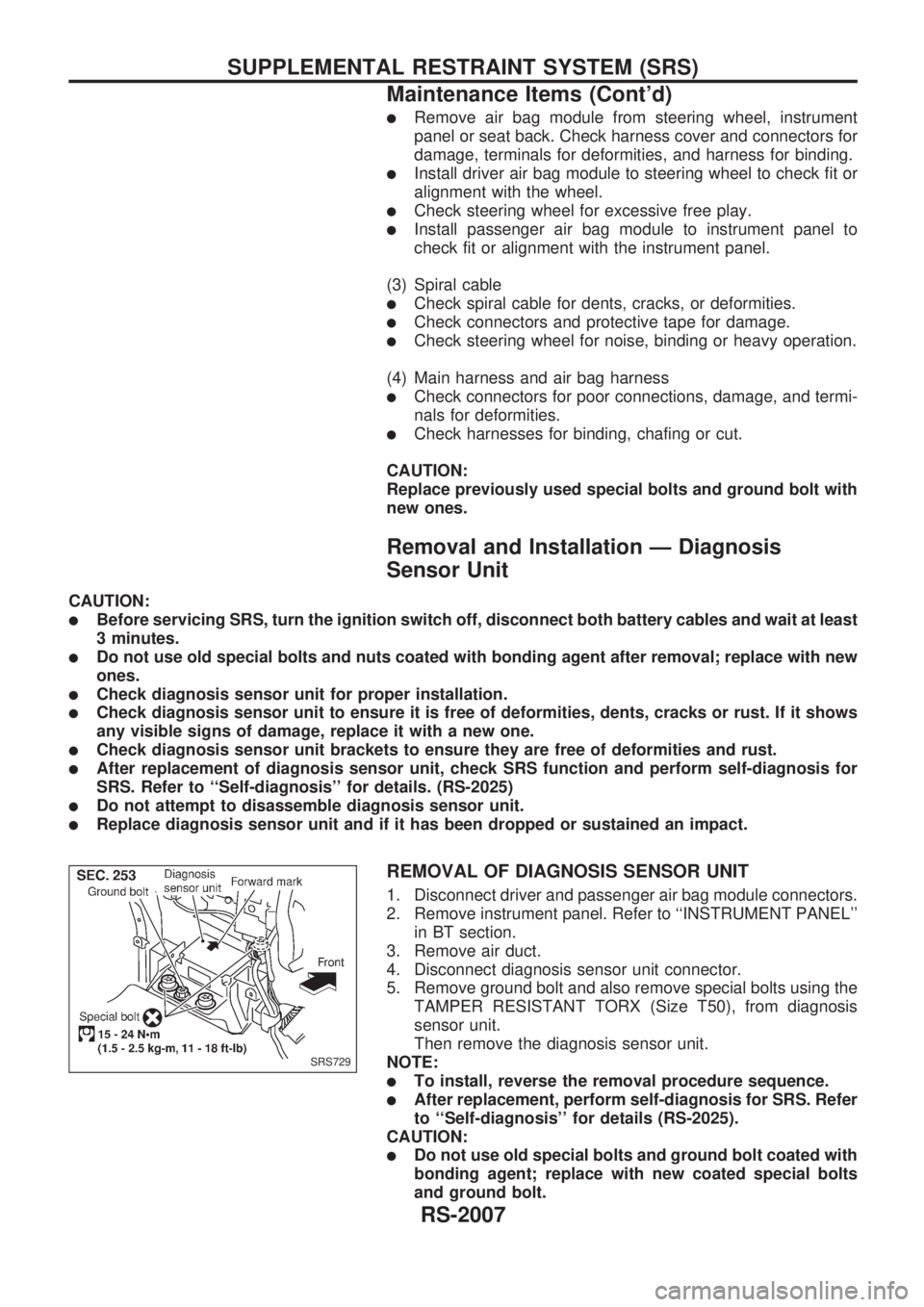
REMOVAL OF DIAGNOSIS SENSOR UNIT
1. Disconnect driver and passenger air bag module connectors.
2. Remove instrument panel. Refer to ``INSTRUMENT PANEL''
in BT section.
3. Remove air duct.
4. Disconnect diagnosis sensor unit connector.
5. Remove ground bolt and also remove special bolts using the
TAMPER RESISTANT TORX (Size T50), from diagnosis
sensor unit.
Then remove the diagnosis sensor unit.
NOTE:
lTo install, reverse the removal procedure sequence.
lAfter replacement, perform self-diagnosis for SRS. Refer
to ``Self-diagnosis'' for details (RS-2025).
CAUTION:
lDo not use old special bolts and ground bolt coated with
bonding agent; replace with new coated special bolts
and ground bolt.
SRS729
SUPPLEMENTAL RESTRAINT SYSTEM (SRS)
Maintenance Items (Cont'd)
RS-2007
Page 630 of 666
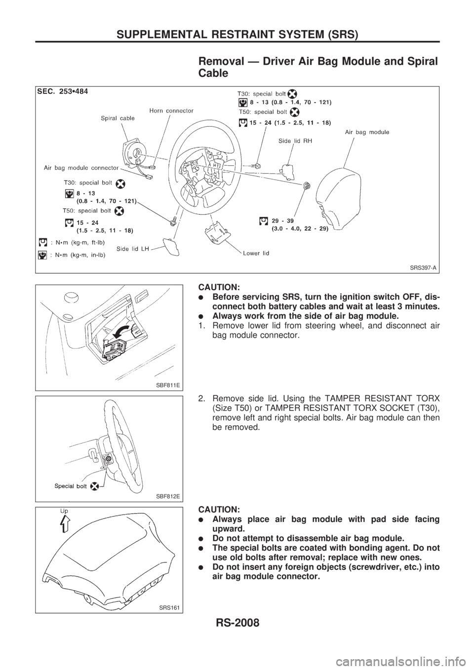
Removal Ð Driver Air Bag Module and Spiral
Cable
CAUTION:
lBefore servicing SRS, turn the ignition switch OFF, dis-
connect both battery cables and wait at least 3 minutes.
lAlways work from the side of air bag module.
1. Remove lower lid from steering wheel, and disconnect air
bag module connector.
2. Remove side lid. Using the TAMPER RESISTANT TORX
(Size T50) or TAMPER RESISTANT TORX SOCKET (T30),
remove left and right special bolts. Air bag module can then
be removed.
CAUTION:
lAlways place air bag module with pad side facing
upward.
lDo not attempt to disassemble air bag module.
lThe special bolts are coated with bonding agent. Do not
use old bolts after removal; replace with new ones.
lDo not insert any foreign objects (screwdriver, etc.) into
air bag module connector.
SRS397-A
SBF811E
SBF812E
SRS161
SUPPLEMENTAL RESTRAINT SYSTEM (SRS)
RS-2008
Page 631 of 666
lReplace air bag module if it has been dropped or sus-
tained an impact.
lDo not expose the air bag module to temperatures
exceeding 90ÉC (194ÉF).
lDo not allow oil, grease or water to come in contact with
the air bag module.
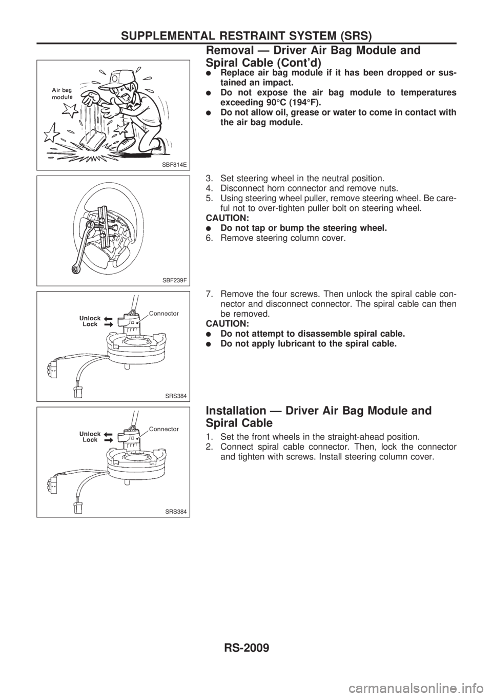
3. Set steering wheel in the neutral position.
4. Disconnect horn connector and remove nuts.
5. Using steering wheel puller, remove steering wheel. Be care-
ful not to over-tighten puller bolt on steering wheel.
CAUTION:
lDo not tap or bump the steering wheel.
6. Remove steering column cover.
7. Remove the four screws. Then unlock the spiral cable con-
nector and disconnect connector. The spiral cable can then
be removed.
CAUTION:
lDo not attempt to disassemble spiral cable.
lDo not apply lubricant to the spiral cable.
Installation Ð Driver Air Bag Module and
Spiral Cable
1. Set the front wheels in the straight-ahead position.
2. Connect spiral cable connector. Then, lock the connector
and tighten with screws. Install steering column cover.
SBF814E
SBF239F
SRS384
SRS384
SUPPLEMENTAL RESTRAINT SYSTEM (SRS)
Removal Ð Driver Air Bag Module and
Spiral Cable (Cont'd)
RS-2009
Page 632 of 666
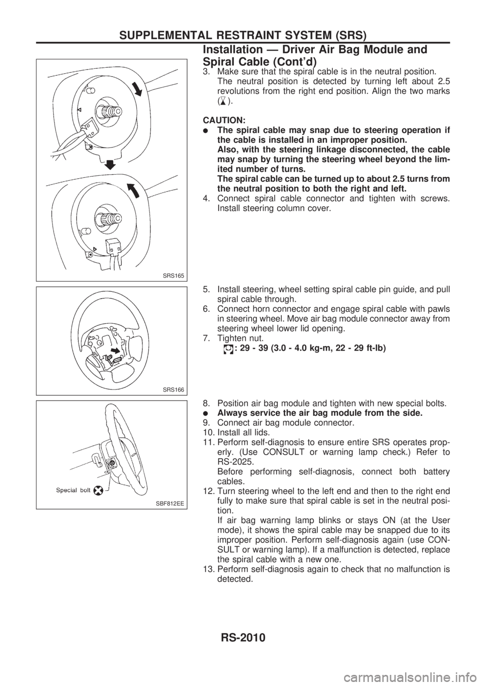
3. Make sure that the spiral cable is in the neutral position.
The neutral position is detected by turning left about 2.5
revolutions from the right end position. Align the two marks
(
,
s).
CAUTION:
lThe spiral cable may snap due to steering operation if
the cable is installed in an improper position.
Also, with the steering linkage disconnected, the cable
may snap by turning the steering wheel beyond the lim-
ited number of turns.
The spiral cable can be turned up to about 2.5 turns from
the neutral position to both the right and left.
4. Connect spiral cable connector and tighten with screws.
Install steering column cover.
5. Install steering, wheel setting spiral cable pin guide, and pull
spiral cable through.
6. Connect horn connector and engage spiral cable with pawls
in steering wheel. Move air bag module connector away from
steering wheel lower lid opening.
7. Tighten nut.
: 29 - 39 (3.0 - 4.0 kg-m, 22 - 29 ft-lb)
8. Position air bag module and tighten with new special bolts.
lAlways service the air bag module from the side.
9. Connect air bag module connector.
10. Install all lids.
11. Perform self-diagnosis to ensure entire SRS operates prop-
erly. (Use CONSULT or warning lamp check.) Refer to
RS-2025.
Before performing self-diagnosis, connect both battery
cables.
12. Turn steering wheel to the left end and then to the right end
fully to make sure that spiral cable is set in the neutral posi-
tion.
If air bag warning lamp blinks or stays ON (at the User
mode), it shows the spiral cable may be snapped due to its
improper position. Perform self-diagnosis again (use CON-
SULT or warning lamp). If a malfunction is detected, replace
the spiral cable with a new one.
13. Perform self-diagnosis again to check that no malfunction is
detected.
SRS165
SRS166
SBF812EE
SUPPLEMENTAL RESTRAINT SYSTEM (SRS)
Installation Ð Driver Air Bag Module and
Spiral Cable (Cont'd)
RS-2010
Page 661 of 666
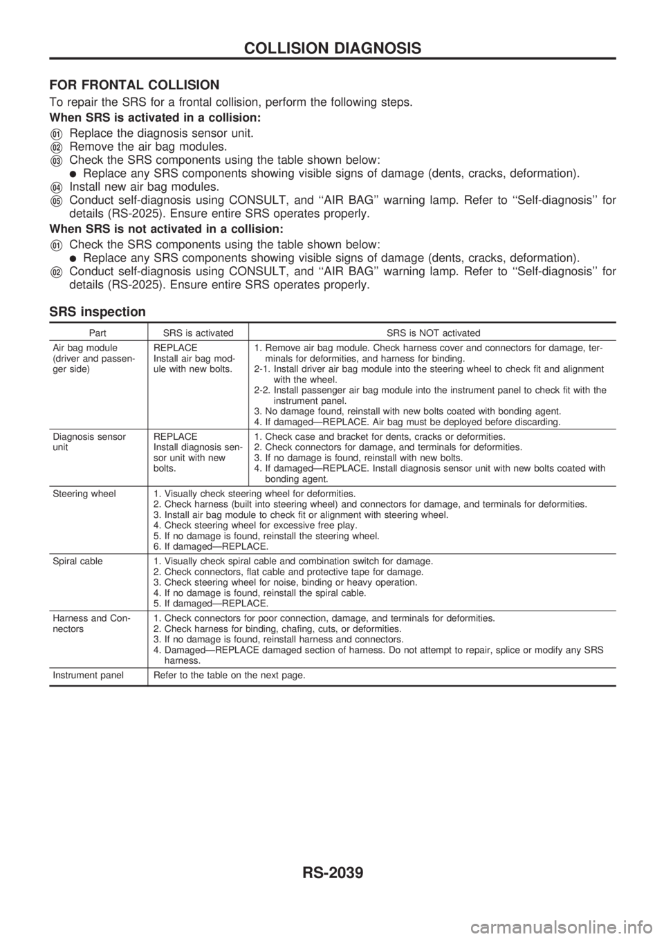
FOR FRONTAL COLLISION
To repair the SRS for a frontal collision, perform the following steps.
When SRS is activated in a collision:
V01Replace the diagnosis sensor unit.
V02Remove the air bag modules.
V03Check the SRS components using the table shown below:
lReplace any SRS components showing visible signs of damage (dents, cracks, deformation).
V04Install new air bag modules.
V05Conduct self-diagnosis using CONSULT, and ``AIR BAG'' warning lamp. Refer to ``Self-diagnosis'' for
details (RS-2025). Ensure entire SRS operates properly.
When SRS is not activated in a collision:
V01Check the SRS components using the table shown below:
lReplace any SRS components showing visible signs of damage (dents, cracks, deformation).
V02Conduct self-diagnosis using CONSULT, and ``AIR BAG'' warning lamp. Refer to ``Self-diagnosis'' for
details (RS-2025). Ensure entire SRS operates properly.
SRS inspection
Part SRS is activated SRS is NOT activated
Air bag module
(driver and passen-
ger side)REPLACE
Install air bag mod-
ule with new bolts.1. Remove air bag module. Check harness cover and connectors for damage, ter-
minals for deformities, and harness for binding.
2-1. Install driver air bag module into the steering wheel to check fit and alignment
with the wheel.
2-2. Install passenger air bag module into the instrument panel to check fit with the
instrument panel.
3. No damage found, reinstall with new bolts coated with bonding agent.
4. If damagedÐREPLACE. Air bag must be deployed before discarding.
Diagnosis sensor
unitREPLACE
Install diagnosis sen-
sor unit with new
bolts.1. Check case and bracket for dents, cracks or deformities.
2. Check connectors for damage, and terminals for deformities.
3. If no damage is found, reinstall with new bolts.
4. If damagedÐREPLACE. Install diagnosis sensor unit with new bolts coated with
bonding agent.
Steering wheel 1. Visually check steering wheel for deformities.
2. Check harness (built into steering wheel) and connectors for damage, and terminals for deformities.
3. Install air bag module to check fit or alignment with steering wheel.
4. Check steering wheel for excessive free play.
5. If no damage is found, reinstall the steering wheel.
6. If damagedÐREPLACE.
Spiral cable 1. Visually check spiral cable and combination switch for damage.
2. Check connectors, flat cable and protective tape for damage.
3. Check steering wheel for noise, binding or heavy operation.
4. If no damage is found, reinstall the spiral cable.
5. If damagedÐREPLACE.
Harness and Con-
nectors1. Check connectors for poor connection, damage, and terminals for deformities.
2. Check harness for binding, chafing, cuts, or deformities.
3. If no damage is found, reinstall harness and connectors.
4. DamagedÐREPLACE damaged section of harness. Do not attempt to repair, splice or modify any SRS
harness.
Instrument panel Refer to the table on the next page.
COLLISION DIAGNOSIS
RS-2039
Page 663 of 666
STEERINGSYSTEM
SECTION
ST
MODIFICATION NOTICE:
Steering column has been changed.
CONTENTS
STEERING WHEEL AND STEERING
COLUMN .............................................................. 2002
Disassembly and Assembly ............................. 2002 SERVICE DATA AND SPECIFICATIONS
(SDS)
.................................................................... 2004
Inspection and Adjustment .............................. 2004
ST
Page 664 of 666
Disassembly and Assembly
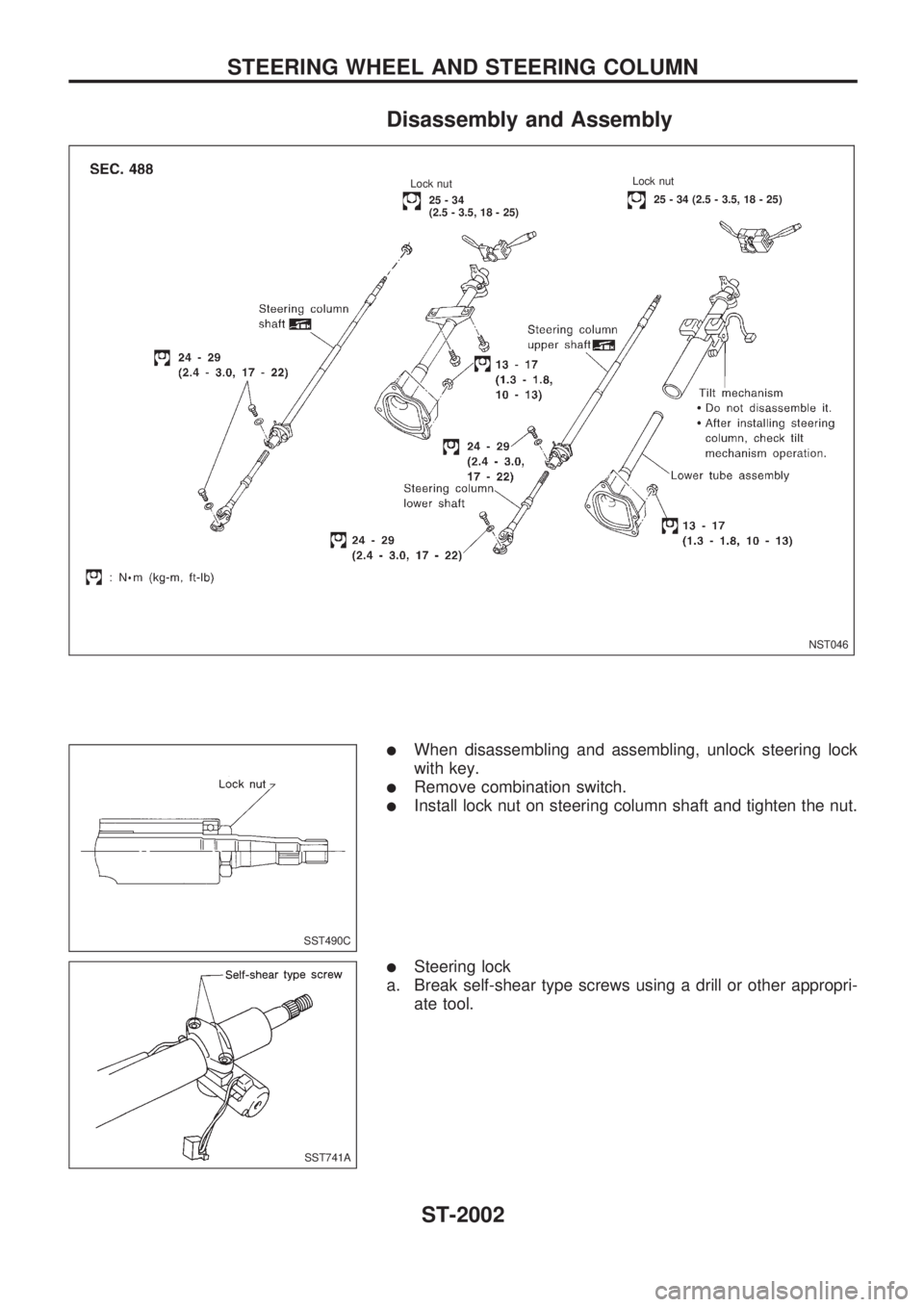
lWhen disassembling and assembling, unlock steering lock
with key.
lRemove combination switch.
lInstall lock nut on steering column shaft and tighten the nut.
lSteering lock
a. Break self-shear type screws using a drill or other appropri-
ate tool.
NST046
..Lock nut.25 - 34 (2.5 - 3.5, 18 - 25)
.Lock nut
...25-34
(2.5 - 3.5, 18 - 25)
.
SST490C
SST741A
STEERING WHEEL AND STEERING COLUMN
ST-2002
Page 665 of 666
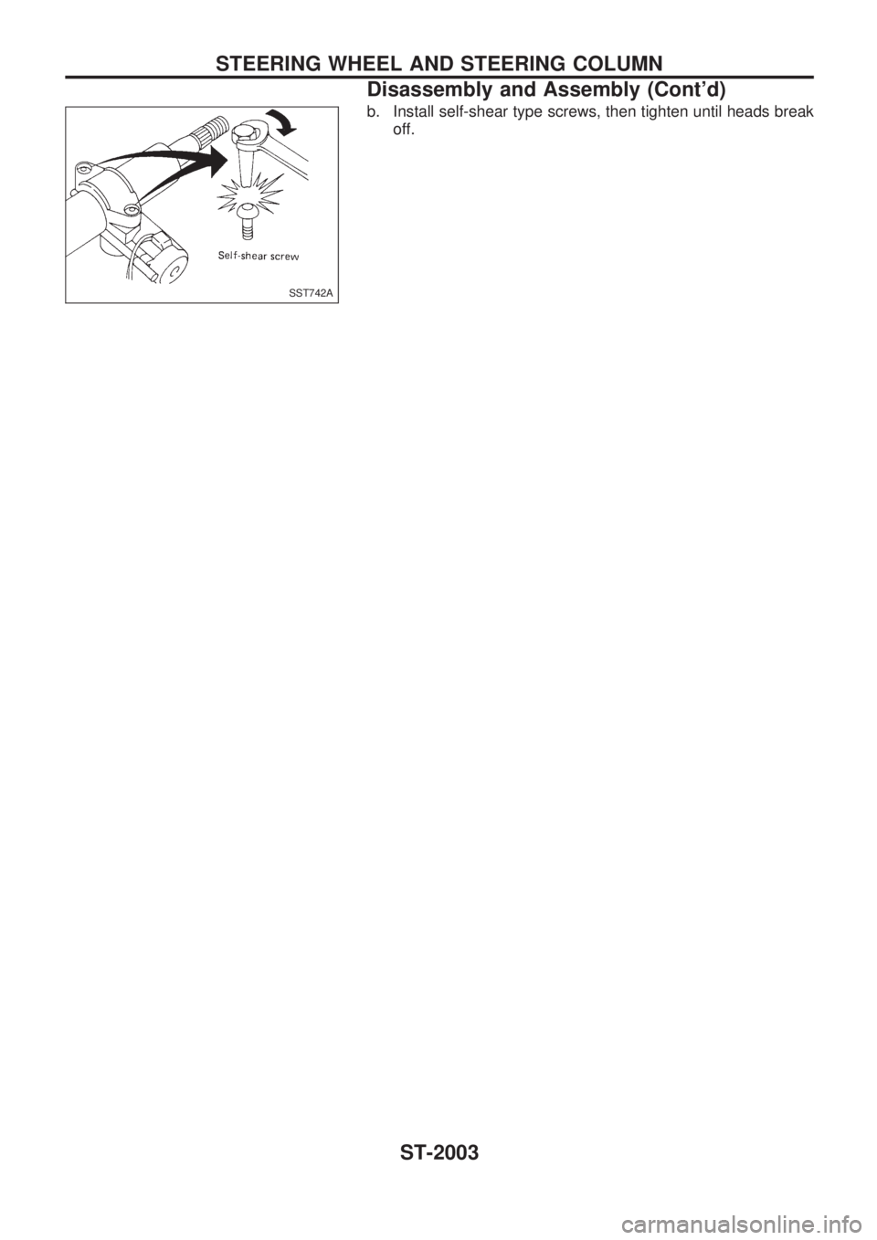
b. Install self-shear type screws, then tighten until heads break
off.
SST742A
STEERING WHEEL AND STEERING COLUMN
Disassembly and Assembly (Cont'd)
ST-2003