1999 NISSAN PICK-UP maintenance
[x] Cancel search: maintenancePage 502 of 666
Supplemental Restraint System (SRS) ªAIR
BAGº and ªSEAT BELT PRE-TENSIONERº
The Supplemental Restraint System such as ªAIR BAGº and ªSEAT BELT PRE-TENSIONERº used along
with a seat belt, helps to reduce the risk or severity of injury to the driver and front passenger in a frontal
collision. The SRS system composition which is available to NISSAN MODEL D22 is as follows (The com-
position varies according to the destination and optional equipment.):
Driver air bag module (located in the center of the steering wheel), front passenger air bag module (located
on the instrument panel on passenger side), seat belt pre-tensioner, a diagnosis sensor unit, warning lamp,
wiring harness and spiral cable.
Information necessary to service the system safely is included in theRS sectionof this Service Manual.
WARNING:
lTo avoid rendering the SRS inoperative, which could increase the risk of personal injury or death
in the event of a collision which would result in air bag inflation, all maintenance must be per-
formed by an authorized NISSAN dealer.
lImproper maintenance, including incorrect removal and installation of the SRS, can lead to per-
sonal injury caused by unintentional activation of the system. For removal of Spiral Cable and
Air Bag Module, see the RS section.
lDo not use electrical test equipment on any circuit related to the SRS unless instructed to in this
Service Manual. Spiral Cable and wiring harnesses (except ªSEAT BELT PRE-TENSIONERº) cov-
ered with yellow insulation either just before the harness connectors or for the complete harness
are related to the SRS.
PRECAUTIONS AND PREPARATIONMANUAL AND AUTO
HA-2002
Page 596 of 666
MAINTENANCE
SECTION
MA
CONTENTS
PRECAUTIONS AND PREPARATION ............... 2002
Supplemental Restraint System (SRS) ²AIR
BAG ²and ²SEAT BELT PRE-TENSIONER ².. 2002
RECOMMENDED FLUIDS AND
LUBRICANTS ...................................................... 2003 Fluids and Lubricants....................................... 2003
SAE Viscosity Number..................................... 2004
MA
Page 597 of 666
Supplemental Restraint System (SRS) ªAIR
BAGº and ªSEAT BELT PRE-TENSIONERº
The Supplemental Restraint System such as ªAIR BAGº and ªSEAT BELT PRE-TENSIONERº used along
with a seat belt, helps to reduce the risk or severity of injury to the driver and front passenger in a frontal
collision. The SRS system composition which is available to NISSAN MODEL D22 is as follows (The com-
position varies according to the destination and optional equipment.):
Driver air bag module (located in the center of the steering wheel), front passenger air bag module (located
on the instrument panel on passenger side), seat belt pre-tensioner, a diagnosis sensor unit, warning lamp,
wiring harness and spiral cable.
Information necessary to service the system safely is included in theRS sectionof this Service Manual.
WARNING:
lTo avoid rendering the SRS inoperative, which could increase the risk of personal injury or death
in the event of a collision which would result in air bag inflation, all maintenance must be per-
formed by an authorized NISSAN dealer.
lImproper maintenance, including incorrect removal and installation of the SRS, can lead to per-
sonal injury caused by unintentional activation of the system. For removal of Spiral Cable and
Air Bag Module, see the RS section.
lDo not use electrical test equipment on any circuit related to the SRS unless instructed to in this
Service Manual. Spiral Cable and wiring harnesses (except ªSEAT BELT PRE-TENSIONERº) cov-
ered with yellow insulation either just before the harness connectors or for the complete harness
are related to the SRS.
PRECAUTIONS AND PREPARATION
MA-2002
Page 623 of 666
RESTRAINTSYSTEM
SECTION
RS
MODIFICATION NOTICE:
lPassenger air bag has been adopted as optional equipment.
lDiagnosis sensor unit has been changed.
lThe air bag system with a diagnosis sensor unit located in the steering wheel has been deleted.
CONTENTS
PRECAUTION ...................................................... 2002
Supplemental Restraint System (SRS) ``AIR
BAG'' ................................................................ 2002
SEAT BELTS ....................................................... 2003
Precaution for Seat Belt Service ..................... 2003
SUPPLEMENTAL RESTRAINT SYSTEM
(SRS) .................................................................... 2004
Precautions for SRS ``AIR BAG'' and ``SEAT
BELT PRE-TENSIONER'' Service................... 2004
Special Service Tools ...................................... 2004
Commercial Service Tool................................. 2005
Description ....................................................... 2005
SRS Component Parts Location...................... 2006
Maintenance Items........................................... 2006
Removal and Installation - Diagnosis Sensor
Unit ................................................................... 2007
Removal - Driver Air Bag Module and Spiral
Cable ................................................................ 2008 Installation - Driver Air Bag Module and Spiral
Cable ................................................................ 2009
Removal - Front Passenger Air Bag Module .. 2011
Installation - Front Passenger Air Bag
Module ............................................................. 2011
Disposal of Air Bag Module ............................. 2012
TROUBLE DIAGNOSES - Supplemental
Restraint System (SRS) ..................................... 2015
Trouble Diagnoses Introduction ....................... 2015
How to Perform Trouble Diagnoses for Quick
and Accurate Repair ........................................ 2017
Schematic ........................................................ 2019
Wiring Diagram - SRS -/LHD Models .............. 2020
Wiring Diagram - SRS -/RHD Models ............. 2023
Self-diagnosis................................................... 2025
Trouble Diagnoses for Air Bag Warning
Lamp ................................................................ 2037
COLLISION DIAGNOSIS ..................................... 2039
RS
Page 624 of 666
Supplemental Restraint System (SRS) ``AIR
BAG''
The Supplemental Restraint System ``AIR BAG'' used along with a seat belt, helps to reduce the risk or
severity of injury to the driver and front passenger in a frontal collision. The SRS composition which is avail-
able to NISSAN MODEL D22 is as follows (The composition varies according to the destination and optional
equipment.):
Driver air bag module (located in the center of the steering wheel), front passenger air bag module (located
on the instrument panel on passenger side), a diagnosis sensor unit, warning lamp, wiring harness and spi-
ral cable.
WARNING:
lTo avoid rendering the SRS inoperative, which could increase the risk of personal injury or death
in the event of a collision which would result in air bag inflation, all maintenance must be per-
formed by an authorized NISSAN dealer.
lImproper maintenance, including incorrect removal and installation of the SRS, can lead to per-
sonal injury caused by unintentional activation of the system.
lDo not use electrical test equipment on any circuit related to the SRS unless instructed to in this
Service Manual. Spiral cable and wiring harnesses covered with yellow insulation either just
before the harness connectors or for the complete harness are related to the SRS.
PRECAUTION
RS-2002
Page 628 of 666
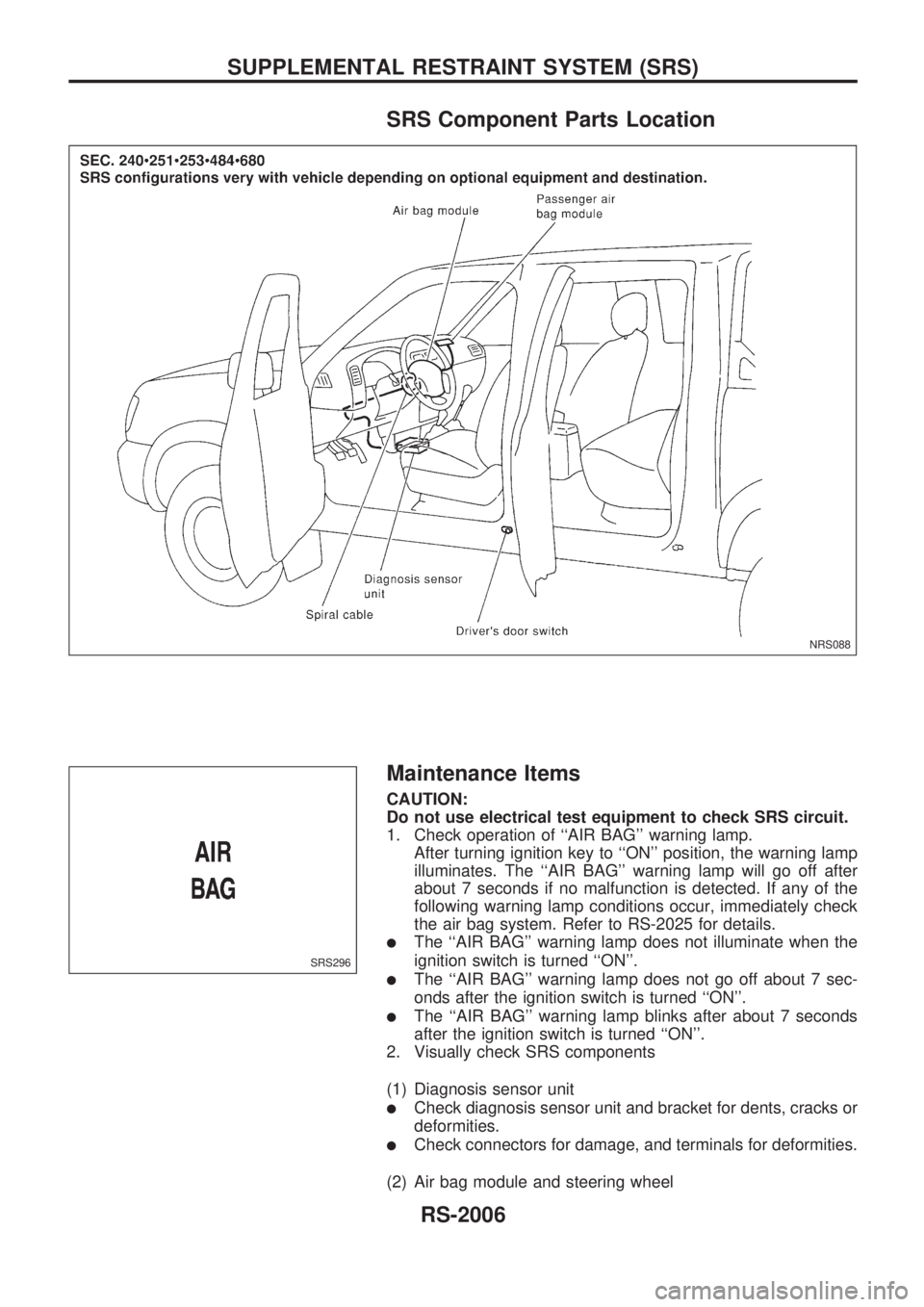
SRS Component Parts Location
Maintenance Items
CAUTION:
Do not use electrical test equipment to check SRS circuit.
1. Check operation of ``AIR BAG'' warning lamp.
After turning ignition key to ``ON'' position, the warning lamp
illuminates. The ``AIR BAG'' warning lamp will go off after
about 7 seconds if no malfunction is detected. If any of the
following warning lamp conditions occur, immediately check
the air bag system. Refer to RS-2025 for details.
lThe ``AIR BAG'' warning lamp does not illuminate when the
ignition switch is turned ``ON''.
lThe ``AIR BAG'' warning lamp does not go off about 7 sec-
onds after the ignition switch is turned ``ON''.
lThe ``AIR BAG'' warning lamp blinks after about 7 seconds
after the ignition switch is turned ``ON''.
2. Visually check SRS components
(1) Diagnosis sensor unit
lCheck diagnosis sensor unit and bracket for dents, cracks or
deformities.
lCheck connectors for damage, and terminals for deformities.
(2) Air bag module and steering wheel
NRS088
SRS296
SUPPLEMENTAL RESTRAINT SYSTEM (SRS)
RS-2006
Page 629 of 666
lRemove air bag module from steering wheel, instrument
panel or seat back. Check harness cover and connectors for
damage, terminals for deformities, and harness for binding.
lInstall driver air bag module to steering wheel to check fit or
alignment with the wheel.
lCheck steering wheel for excessive free play.
lInstall passenger air bag module to instrument panel to
check fit or alignment with the instrument panel.
(3) Spiral cable
lCheck spiral cable for dents, cracks, or deformities.
lCheck connectors and protective tape for damage.
lCheck steering wheel for noise, binding or heavy operation.
(4) Main harness and air bag harness
lCheck connectors for poor connections, damage, and termi-
nals for deformities.
lCheck harnesses for binding, chafing or cut.
CAUTION:
Replace previously used special bolts and ground bolt with
new ones.
Removal and Installation Ð Diagnosis
Sensor Unit
CAUTION:
lBefore servicing SRS, turn the ignition switch off, disconnect both battery cables and wait at least
3 minutes.
lDo not use old special bolts and nuts coated with bonding agent after removal; replace with new
ones.
lCheck diagnosis sensor unit for proper installation.
lCheck diagnosis sensor unit to ensure it is free of deformities, dents, cracks or rust. If it shows
any visible signs of damage, replace it with a new one.
lCheck diagnosis sensor unit brackets to ensure they are free of deformities and rust.
lAfter replacement of diagnosis sensor unit, check SRS function and perform self-diagnosis for
SRS. Refer to ``Self-diagnosis'' for details. (RS-2025)
lDo not attempt to disassemble diagnosis sensor unit.
lReplace diagnosis sensor unit and if it has been dropped or sustained an impact.
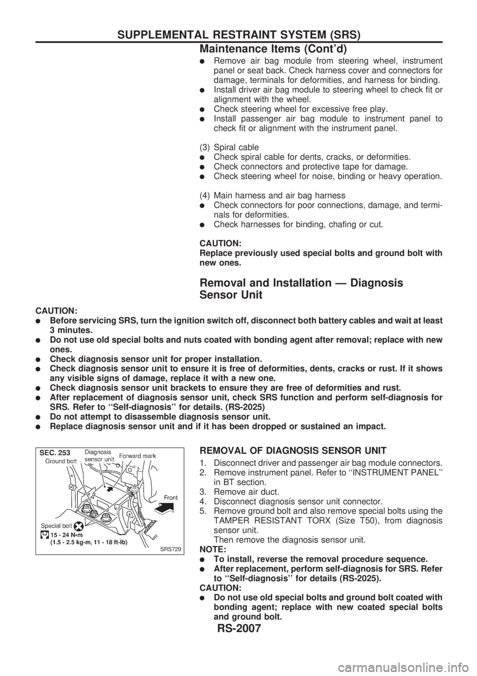
REMOVAL OF DIAGNOSIS SENSOR UNIT
1. Disconnect driver and passenger air bag module connectors.
2. Remove instrument panel. Refer to ``INSTRUMENT PANEL''
in BT section.
3. Remove air duct.
4. Disconnect diagnosis sensor unit connector.
5. Remove ground bolt and also remove special bolts using the
TAMPER RESISTANT TORX (Size T50), from diagnosis
sensor unit.
Then remove the diagnosis sensor unit.
NOTE:
lTo install, reverse the removal procedure sequence.
lAfter replacement, perform self-diagnosis for SRS. Refer
to ``Self-diagnosis'' for details (RS-2025).
CAUTION:
lDo not use old special bolts and ground bolt coated with
bonding agent; replace with new coated special bolts
and ground bolt.
SRS729
SUPPLEMENTAL RESTRAINT SYSTEM (SRS)
Maintenance Items (Cont'd)
RS-2007
Page 656 of 666
![NISSAN PICK-UP 1999 Repair Manual DIAGNOSTIC PROCEDURE 6 (Continued from
DIAGNOSTIC PROCEDURE 2)
Inspecting SRS malfunctioning record
Is it the first time for maintenance of
SRS?
Yes
cNo
``SELF-DIAG [PAST]
(which was previously
ente NISSAN PICK-UP 1999 Repair Manual DIAGNOSTIC PROCEDURE 6 (Continued from
DIAGNOSTIC PROCEDURE 2)
Inspecting SRS malfunctioning record
Is it the first time for maintenance of
SRS?
Yes
cNo
``SELF-DIAG [PAST]
(which was previously
ente](/manual-img/5/57373/w960_57373-655.png)
DIAGNOSTIC PROCEDURE 6 (Continued from
DIAGNOSTIC PROCEDURE 2)
Inspecting SRS malfunctioning record
Is it the first time for maintenance of
SRS?
Yes
cNo
``SELF-DIAG [PAST]''
(which was previously
entered) is still retained in
memory.
Go to DIAGNOSTIC PRO-
CEDURE 4 (RS-2030).
Go to DIAGNOSTIC PROCEDURE 8
(RS-2034).
DIAGNOSTIC PROCEDURE 7 (Continued from
DIAGNOSTIC PROCEDURE 3) (
without
CONSULT)
Inspecting SRS malfunctioning record
Is it the first time for maintenance of
SRS?
Yes
cNo
Diagnosis results (previ-
ously stored in the
memory) might not be
erased after repair.
Go to DIAGNOSTIC PRO-
CEDURE 5, step 5 (RS-
2032).
GO TO DIAGNOSTIC PROCEDURE 8
(RS-2034).Further inspection cannot be
performed without CONSULT.
DIAGNOSTIC PROCEDURE 8 (with CONSULT)
Inspecting SRS intermittent malfunction by using CONSULT
Ð Diagnosis mode
1. Turn ignition switch ``OFF''.
2. Connect ``CONSULT'' to Data link connector.
3. Turn ignition switch ``ON''.
4. Touch ``START''.
SRS733
SRS046
.
.
TROUBLE DIAGNOSES Ð Supplemental Restraint System (SRS)
Self-diagnosis (Cont'd)
RS-2034