Page 496 of 666

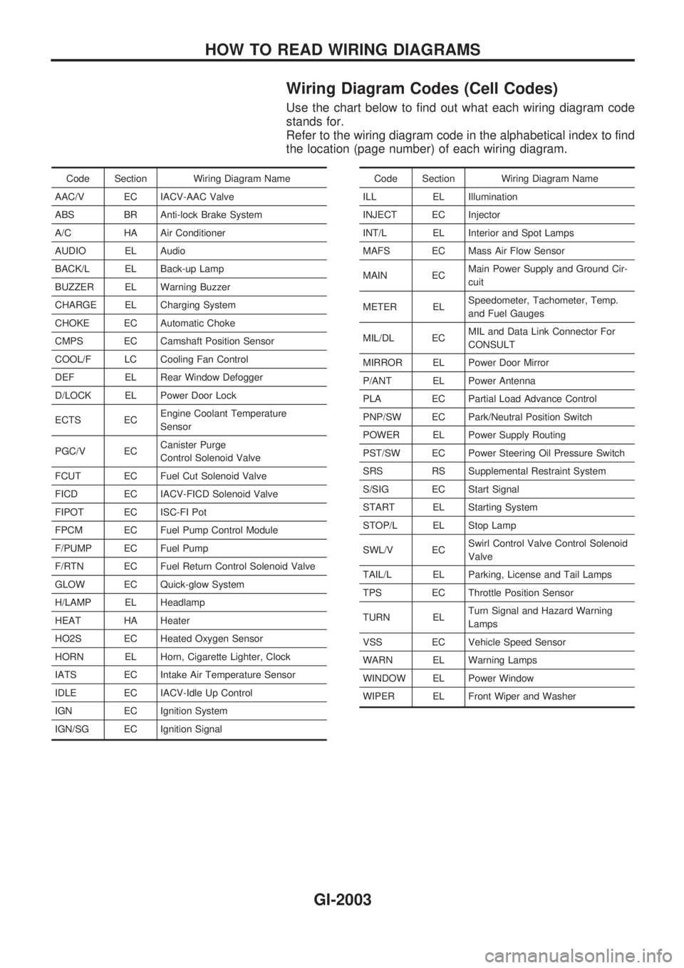
Wiring Diagram Codes (Cell Codes)
Use the chart below to find out what each wiring diagram code
stands for.
Refer to the wiring diagram code in the alphabetical index to find
the location (page number) of each wiring diagram.
Code Section Wiring Diagram Name
AAC/V EC IACV-AAC Valve
ABS BR Anti-lock Brake System
A/C HA Air Conditioner
AUDIO EL Audio
BACK/L EL Back-up Lamp
BUZZER EL Warning Buzzer
CHARGE EL Charging System
CHOKE EC Automatic Choke
CMPS EC Camshaft Position Sensor
COOL/F LC Cooling Fan Control
DEF EL Rear Window Defogger
D/LOCK EL Power Door Lock
ECTS ECEngine Coolant Temperature
Sensor
PGC/V ECCanister Purge
Control Solenoid Valve
FCUT EC Fuel Cut Solenoid Valve
FICD EC IACV-FICD Solenoid Valve
FIPOT EC ISC-FI Pot
FPCM EC Fuel Pump Control Module
F/PUMP EC Fuel Pump
F/RTN EC Fuel Return Control Solenoid Valve
GLOW EC Quick-glow System
H/LAMP EL Headlamp
HEAT HA Heater
HO2S EC Heated Oxygen Sensor
HORN EL Horn, Cigarette Lighter, Clock
IATS EC Intake Air Temperature Sensor
IDLE EC IACV-Idle Up Control
IGN EC Ignition System
IGN/SG EC Ignition SignalCode Section Wiring Diagram Name
ILL EL Illumination
INJECT EC Injector
INT/L EL Interior and Spot Lamps
MAFS EC Mass Air Flow Sensor
MAIN ECMain Power Supply and Ground Cir-
cuit
METER ELSpeedometer, Tachometer, Temp.
and Fuel Gauges
MIL/DL ECMIL and Data Link Connector For
CONSULT
MIRROR EL Power Door Mirror
P/ANT EL Power Antenna
PLA EC Partial Load Advance Control
PNP/SW EC Park/Neutral Position Switch
POWER EL Power Supply Routing
PST/SW EC Power Steering Oil Pressure Switch
SRS RS Supplemental Restraint System
S/SIG EC Start Signal
START EL Starting System
STOP/L EL Stop Lamp
SWL/V ECSwirl Control Valve Control Solenoid
Valve
TAIL/L EL Parking, License and Tail Lamps
TPS EC Throttle Position Sensor
TURN ELTurn Signal and Hazard Warning
Lamps
VSS EC Vehicle Speed Sensor
WARN EL Warning Lamps
WINDOW EL Power Window
WIPER EL Front Wiper and Washer
HOW TO READ WIRING DIAGRAMS
GI-2003
Page 534 of 666

Self-diagnosis
INTRODUCTION AND GENERAL DESCRIPTION
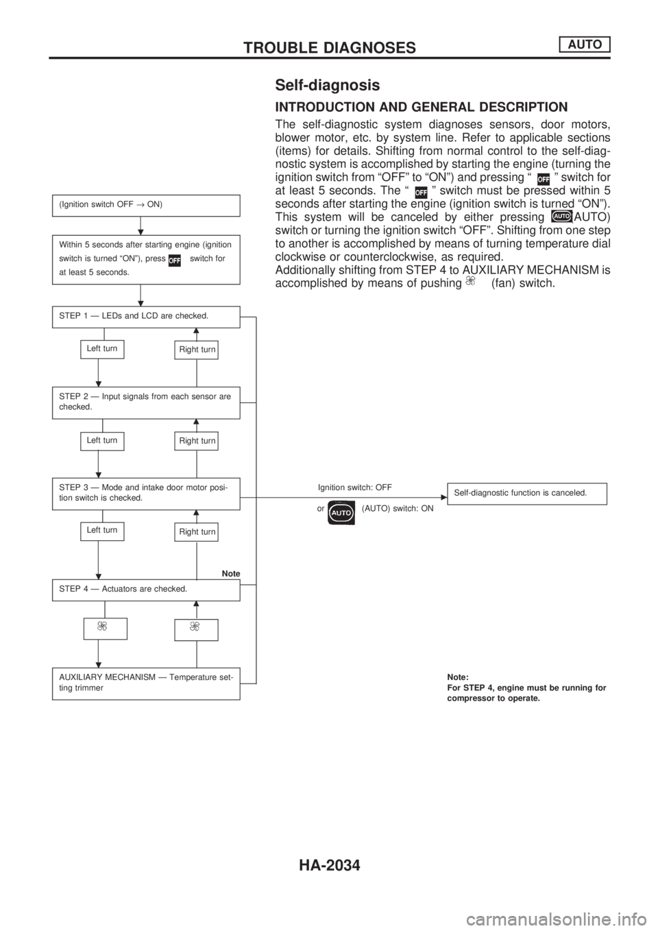
The self-diagnostic system diagnoses sensors, door motors,
blower motor, etc. by system line. Refer to applicable sections
(items) for details. Shifting from normal control to the self-diag-
nostic system is accomplished by starting the engine (turning the
ignition switch from ªOFFº to ªONº) and pressing ª
º switch for
at least 5 seconds. The ª
º switch must be pressed within 5
seconds after starting the engine (ignition switch is turned ªONº).
This system will be canceled by either pressing
(AUTO)
switch or turning the ignition switch ªOFFº. Shifting from one step
to another is accomplished by means of turning temperature dial
clockwise or counterclockwise, as required.
Additionally shifting from STEP 4 to AUXILIARY MECHANISM is
accomplished by means of pushing
(fan) switch.
(Ignition switch OFF®ON)
Within 5 seconds after starting engine (ignition
switch is turned ªONº), press
switch for
at least 5 seconds.
STEP 1 Ð LEDs and LCD are checked.
m
Left turnRight turn
STEP 2 Ð Input signals from each sensor are
checked.
m
Left turnRight turn
STEP 3 Ð Mode and intake door motor posi-
tion switch is checked.Ignition switch: OFFc
or(AUTO) switch: ONSelf-diagnostic function is canceled.m
Left turnRight turn
Note
STEP 4 Ð Actuators are checked.
m
AUXILIARY MECHANISM Ð Temperature set-
ting trimmerNote:
For STEP 4, engine must be running for
compressor to operate.
.
.
.
.
.
.
TROUBLE DIAGNOSESAUTO
HA-2034
Page 535 of 666
STEP-BY-STEP PROCEDURE
Turn ignition switch ON.
Set in self-diagnostic mode. Within 5 sec-
onds after starting engine (ignition switch
is turned ªONº.), press
switch for at
least 5 seconds.
STEP 1 - LEDs AND LCD ARE
CHECKED.
Do all LEDs and LCD illuminate?
Yes
cNo
Malfunctioning
switch, LED or LCD.
Replace A/C auto amp.
Turn temperature dial clockwise.
Advance to self-diagnosis STEP 2?
Yes
cNo
Malfunctioning temperature
dial.
Replace A/C auto amp.
Turn temperature dial counterclockwise.
Return to self-diagnosis STEP 1?
Yes
cNo
Malfunctioning temperature
dial.
Replace A/C auto amp.
Turn temperature dial clockwise.
VA(Go to next page.)
RHA526G
RHA527G
.
.
.
.
.
.
.
.
TROUBLE DIAGNOSESAUTO
Self-diagnosis (Cont'd)
HA-2035
Page 536 of 666
VA
STEP 2 - SENSOR CIRCUITS ARE
CHECKED FOR OPEN OR SHORT
CIRCUIT.
Does code No.
appear on the dis-
play?
YesNo
.
Turn temperature
dial clockwise.Refer to the following chart for malfunctioning code
No.
(If two or more sensors malfunction, corresponding
code Nos. blink respectively two times.)
*1: Conduct self-diagnosis STEP 2 under sunshine.
When conducting indoors, aim a light (more than
60W) at sunload sensor, otherwise Code No.
will indicate despite that sunload sensor is func-
tioning properly.
VB
(Go to next page.)
Code No.Malfunctioning sensor
(including circuits)Reference
page
Ambient sensor HA-2080A/C LED
In-vehicle sensor HA-2082A/C LED
Sunload sensor*1 HA-2084A/C LED
Air mix door motor PBR HA-2055A/C LED
RHA970DA
RHA528G
RHA501A
.
.
.
TROUBLE DIAGNOSESAUTO
Self-diagnosis (Cont'd)
HA-2036
Page 537 of 666
VB
STEP 3 - MODE DOOR POSITIONS
ARE CHECKED.
Does code No.
appear on the dis-
play?
YesNo
.
Turn temperature
dial clockwise.Mode door motor position switch is malfunctioning.
(If two or more mode doors are out of order, corre-
sponding code numbers blink respectively two
times.)
*1: If mode door motor harness connector is
disconnected, the following display pattern will
appear.
®
®®®®þ
VC
(Go to next page.)
Code
No.*1Mode door positionReference
page
VENT
HA-2049
B/L
FOOT
D/F
DEF
RHA869DC
RHA168DA
RHA498A
.
.
.
TROUBLE DIAGNOSESAUTO
Self-diagnosis (Cont'd)
HA-2037
Page 539 of 666
AUXILIARY MECHANISM: Temperature setting
trimmer
The trimmer compensates for differences in range of 3ÉC
between temperature setting (displayed digitally) and tempera-
ture felt by driver.
Operating procedures for this trimmer are as follows:
lBegin Self-diagnosis STEP 4 mode.
lPress(fan) switch to set system in auxiliary mode.
lTurn temperature dial clockwise or counterclockwise as
desired. Temperature will change at a rate of 1ÉC each time
a switch is pressed.
When battery cable is disconnected, trimmer operation is
canceled. Temperature set becomes that of initial condition,
i.e. 0ÉC.
RHA581G
TROUBLE DIAGNOSESAUTO
Self-diagnosis (Cont'd)
HA-2039
Page 543 of 666
5. Check temperature dial
a. Turn temperature dial counterclockwise until 18ÉC is dis-
played.
b. Check for cold air at discharge air outlets.
If NG, go to trouble diagnosis procedure for insufficient cooling
(HA-2075).
If OK, continue with next check.
c. Turn temperature dial clockwise until 32ÉC is displayed.
d. Check for hot air at discharge air outlets.
If NG, go to trouble diagnosis procedure for insufficient heating
(HA-2076).
If OK, continue with next check.
RHA522G
TROUBLE DIAGNOSESAUTO
Operational Check (Cont'd)
HA-2043
Page 551 of 666
COMPONENT INSPECTION
Mode door motor
Terminal No.
Mode door operation Direction of side link rotation
V8V7
Å@VENT®DEF Counterclockwise
þ þ STOP STOP
@
ÅDEF®VENT Clockwise
CONTROL LINKAGE ADJUSTMENT
Mode door
1. Install mode door motor on heater unit and connect it to main
harness.
2. Set up code No.
in Self-diagnosis STEP 4. Refer to
HA-2038.
3. Move side link by hand and hold mode door in DEF mode.
4. Make sure mode door operates properly when changing from
code No.
toby pushing DEF switch.
VENT B/L B/L FOOT D/F DEF
RHA480H
RHA481H
RHA472H
TROUBLE DIAGNOSESAUTO
Mode Door Motor (Cont'd)
HA-2051