1999 LAND ROVER DISCOVERY bonnet
[x] Cancel search: bonnetPage 1141 of 1529
CORROSION PREVENTION AND SEALING
77-4-8 CORROSION PREVENTION
After refitting mechanical components, including hoses and pipes and other fixtures, mask off the brake discs and
apply a coat of approved underbody wax.
NOTE: Where repairs include the application of finish paint coats in the areas requiring underbody wax, carry out paint
operations before applying wax.
Cavity wax injection
Areas treated with cavity wax are shown in the previous figures. After repairs, always re-treat these areas with an
approved cavity wax. In addition, treat all interior surfaces which have been disturbed during repairs whether they
have been treated in production or not. This includes all box members, cavities and door interiors. It is permissible to
drill extra holes for access where necessary, provided these are not positioned in load-bearing members. Ensure that
such holes are treated with a suitable zinc rich primer, brushed with wax and then sealed with a rubber grommet.
Before wax injection, ensure that the cavity to be treated is free from any contamination or foreign matter. Where
necessary, clear out any debris using compressed air.
Ensure that cavity wax is applied AFTER the final paint process and BEFORE refitting any trim components.
During application, ensure that the wax covers all flange and seam areas and that it is adequately applied to all
repaired areas of both new and existing panels.
It should be noted that new panel assemblies and complete body shells are supplied without wax injection treatment.
Ensure that such treatment is carried out after repairs.
Effective cavity wax protection is vital. Always observe the following points:
lComplete all paint refinish operations before wax application;
lClean body panel areas and blow-clean cavities if necessary, before treatment;
lMaintain a temperature of 18° C (64° F) during application and drying;
lCheck the spray pattern of injection equipment;
lMask off all areas not to be wax coated and which could be contaminated by wax overspray;
lRemove body fixings, such as seat belt retractors, if contamination is at all likely;
lMove door glasses to fully closed position before treating door interiors;
lTreat body areas normally covered by trim before refitting items;
lCheck that body and door drain holes are clear after the protective wax has dried;
lKeep all equipment clean, especially wax injection nozzles.
Underbody wax
The underbody wax must be reinstated following all repairs affecting floor panels. The wax is applied over paints and
underbody sealers.
Remove old underbody wax completely from a zone extending at least 200 mm (7.874 in) beyond the area where new
underbody sealer is to be applied.
Engine bay wax
Reinstate all protective engine bay wax disturbed during repairs using an approved material.
Where repairs have involved replacement of engine bay panels, treat the entire engine compartment including all
components, clips and other fixtures with an approved underbonnet lacquer or wax.
+ BODY SEALING MATERIALS, MATERIALS AND APPLICATIONS, Approved materials.
Page 1165 of 1529
HEATING AND VENTILATION
80-8DESCRIPTION AND OPERATION
Control panel
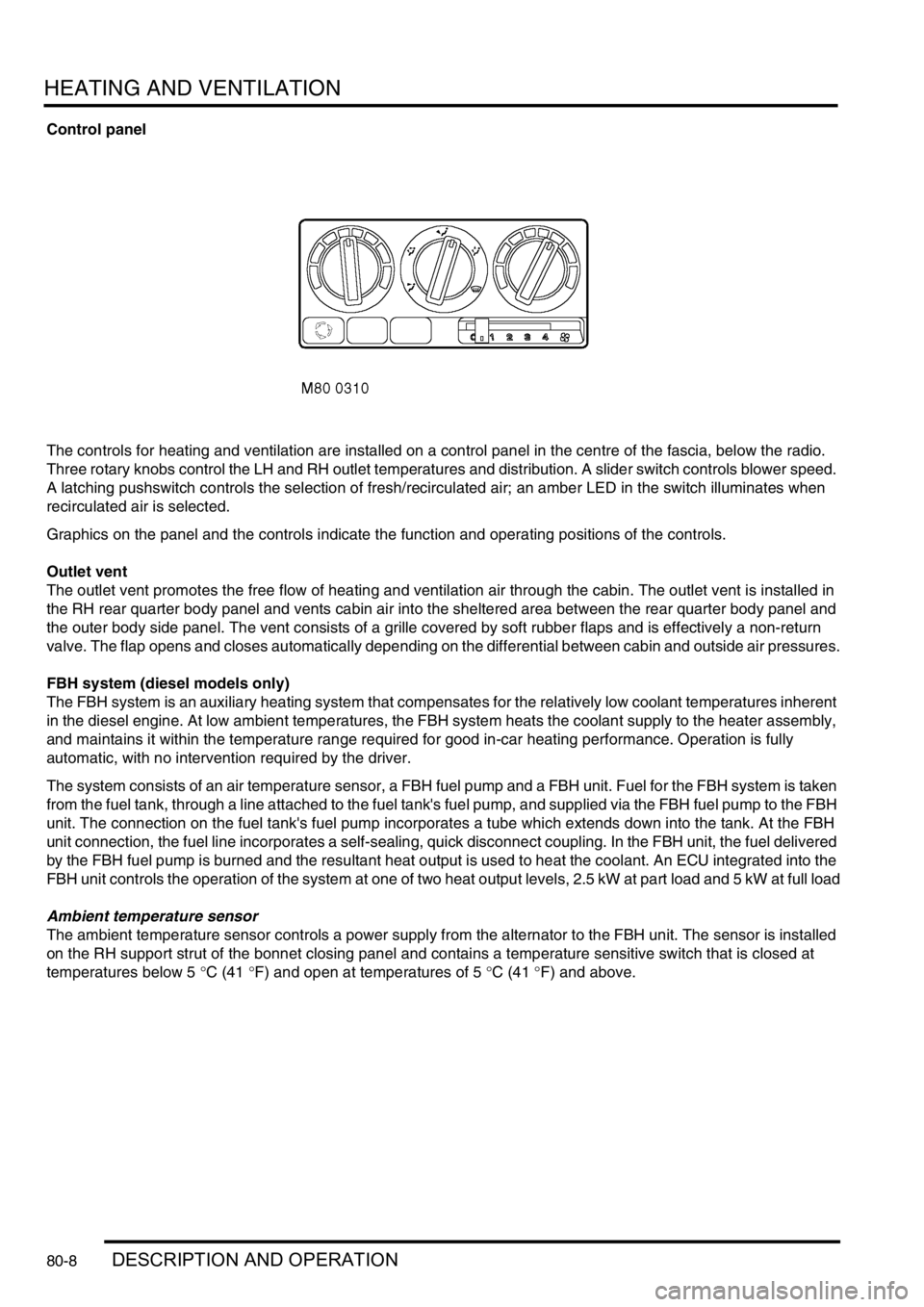
The controls for heating and ventilation are installed on a control panel in the centre of the fascia, below the radio.
Three rotary knobs control the LH and RH outlet temperatures and distribution. A slider switch controls blower speed.
A latching pushswitch controls the selection of fresh/recirculated air; an amber LED in the switch illuminates when
recirculated air is selected.
Graphics on the panel and the controls indicate the function and operating positions of the controls.
Outlet vent
The outlet vent promotes the free flow of heating and ventilation air through the cabin. The outlet vent is installed in
the RH rear quarter body panel and vents cabin air into the sheltered area between the rear quarter body panel and
the outer body side panel. The vent consists of a grille covered by soft rubber flaps and is effectively a non-return
valve. The flap opens and closes automatically depending on the differential between cabin and outside air pressures.
FBH system (diesel models only)
The FBH system is an auxiliary heating system that compensates for the relatively low coolant temperatures inherent
in the diesel engine. At low ambient temperatures, the FBH system heats the coolant supply to the heater assembly,
and maintains it within the temperature range required for good in-car heating performance. Operation is fully
automatic, with no intervention required by the driver.
The system consists of an air temperature sensor, a FBH fuel pump and a FBH unit. Fuel for the FBH system is taken
from the fuel tank, through a line attached to the fuel tank's fuel pump, and supplied via the FBH fuel pump to the FBH
unit. The connection on the fuel tank's fuel pump incorporates a tube which extends down into the tank. At the FBH
unit connection, the fuel line incorporates a self-sealing, quick disconnect coupling. In the FBH unit, the fuel delivered
by the FBH fuel pump is burned and the resultant heat output is used to heat the coolant. An ECU integrated into the
FBH unit controls the operation of the system at one of two heat output levels, 2.5 kW at part load and 5 kW at full load
Ambient temperature sensor
The ambient temperature sensor controls a power supply from the alternator to the FBH unit. The sensor is installed
on the RH support strut of the bonnet closing panel and contains a temperature sensitive switch that is closed at
temperatures below 5 °C (41 °F) and open at temperatures of 5 °C (41 °F) and above.
Page 1220 of 1529
AIR CONDITIONING
REPAIRS 82-31
Fan - condenser
$% 82.15.01
Remove
1.Remove front grille.
+ EXTERIOR FITTINGS, REPAIRS,
Grille - front - up to 03MY.
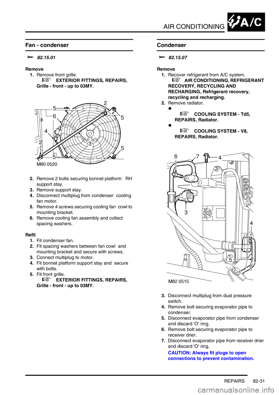
2.Remove 2 bolts securing bonnet platform RH
support stay.
3.Remove support stay.
4.Disconnect multiplug from condenser cooling
fan motor.
5.Remove 4 screws securing cooling fan cowl to
mounting bracket.
6.Remove cooling fan assembly and collect
spacing washers.
Refit
1.Fit condenser fan.
2.Fit spacing washers between fan cowl and
mounting bracket and secure with screws.
3.Connect multiplug to motor.
4.Fit bonnet platform support stay and secure
with bolts.
5.Fit front grille.
+ EXTERIOR FITTINGS, REPAIRS,
Grille - front - up to 03MY.
Condenser
$% 82.15.07
Remove
1.Recover refrigerant from A/C system.
+ AIR CONDITIONING, REFRIGERANT
RECOVERY, RECYCLING AND
RECHARGING, Refrigerant recovery,
recycling and recharging.
2.Remove radiator.
l
+ COOLING SYSTEM - Td5,
REPAIRS, Radiator.
l
+ COOLING SYSTEM - V8,
REPAIRS, Radiator.
3.Disconnect multiplug from dual pressure
switch.
4.Remove bolt securing evaporator pipe to
condenser.
5.Disconnect evaporator pipe from condenser
and discard 'O' ring.
6.Remove bolt securing evaporator pipe to
receiver drier.
7.Disconnect evaporator pipe from receiver drier
and discard 'O' ring.
CAUTION: Always fit plugs to open
connections to prevent contamination.
Page 1248 of 1529
WIPERS AND WASHERS
DESCRIPTION AND OPERATION 84-13
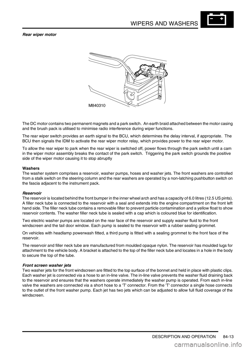
Rear wiper motor
The DC motor contains two permanent magnets and a park switch. An earth braid attached between the motor casing
and the brush pack is utilised to minimise radio interference during wiper functions.
The rear wiper switch provides an earth signal to the BCU, which determines the delay interval, if appropriate. The
BCU then signals the IDM to activate the rear wiper motor relay, which provides power to the rear wiper motor.
To allow the rear wiper to park when the rear wiper is switched off, power flows through the park switch until a cam
in the wiper motor assembly breaks the contact of the park switch. Triggering the park switch grounds the positive
side of the wiper motor causing it to stop abruptly
Washers
The washer system comprises a reservoir, washer pumps, hoses and washer jets. The front washers are controlled
from a stalk switch on the steering column and the rear washers are operated by a non-latching pushbutton switch on
the fascia adjacent to the instrument pack.
Reservoir
The reservoir is located behind the front bumper in the inner wheel arch and has a capacity of 6.0 litres (12.5 US pints).
A filler neck tube is connected to the reservoir with a seal and extends into the engine compartment on the front left
hand side. The filler neck tube contains a removable filter to prevent particle contamination and a yellow float to show
reservoir contents. The washer filler neck tube is sealed with a cap which is coloured blue for identification.
Two electric washer pumps are located on the rear face of the reservoir and supply washer fluid to the front
windscreen and the tail door window. Each pump is sealed to the reservoir with a rubber sealing grommet.
On vehicles with headlamp powerwash fitted, a third pump is fitted with a sealing grommet to the front face of the
reservoir.
The reservoir and filler neck tube are manufactured from moulded opaque nylon. The reservoir has moulded lugs for
attachment to the vehicle body. A bracket is attached to the top of the filler neck tube and locates in a hole in the body
to secure the top of the tube.
Front screen washer jets
Two washer jets for the front windscreen are fitted to the top surface of the bonnet and held in place with plastic clips.
Each washer jet is connected via a hose to an in-line valve. The in-line valve prevents the washer fluid draining back
to the reservoir and ensures that the washers operate immediately the washer pump is operated. From each in-line
valve the washers are connected via a short hose to a 'T' connector. From the 'T' connector a single hose connects
to the outlet of the front washer pump. Each jet has two jets which can be adjusted to allow full fluid coverage of the
windscreen.
Page 1258 of 1529
WIPERS AND WASHERS
REPAIRS 84-23
Jet - washer - windscreen
$% 84.10.08
Remove
1.Carefully pull the elbow from the washer jet.
2.Place a protective covering around the washer
jet, then release and remove washer jet.
Refit
1.Fit washer jet to its location in the bonnet, and
remove the protective material.
2.Connect the washer tube, ensuring that it is
pushed fully onto the stub pipe.
Page 1278 of 1529
LIGHTING
REPAIRS 86-2-5
Headlamp - from 03MY
$% 86.40.49
Remove
1.Remove front grille.
+ EXTERIOR FITTINGS, REPAIRS,
Grille - front - from 03MY.
2.Protect bumper.
CAUTION: Always protect paintwork when
removing or refitting any body trims or
bumpers.
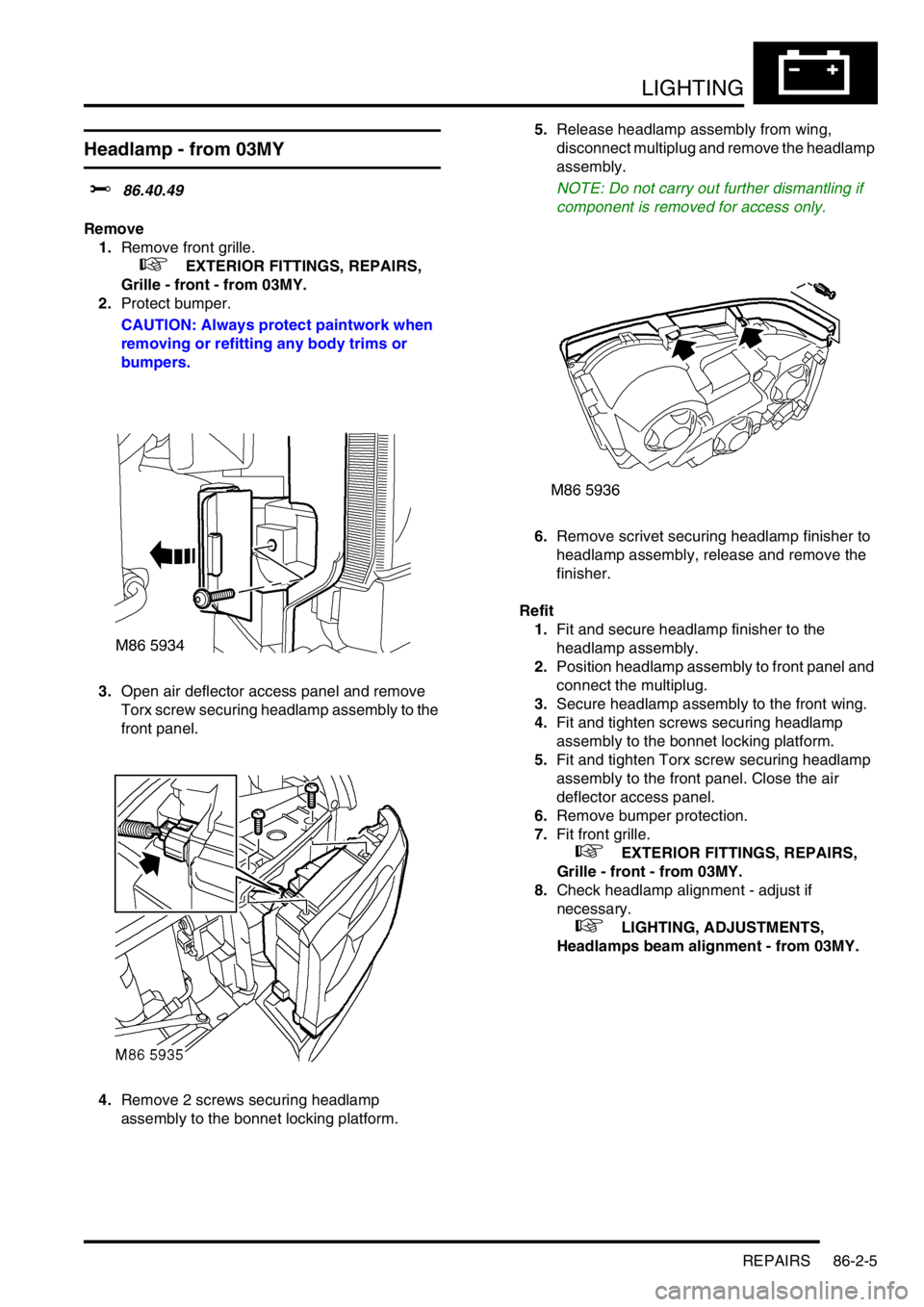
3.Open air deflector access panel and remove
Torx screw securing headlamp assembly to the
front panel.
4.Remove 2 screws securing headlamp
assembly to the bonnet locking platform.5.Release headlamp assembly from wing,
disconnect multiplug and remove the headlamp
assembly.
NOTE: Do not carry out further dismantling if
component is removed for access only.
6.Remove scrivet securing headlamp finisher to
headlamp assembly, release and remove the
finisher.
Refit
1.Fit and secure headlamp finisher to the
headlamp assembly.
2.Position headlamp assembly to front panel and
connect the multiplug.
3.Secure headlamp assembly to the front wing.
4.Fit and tighten screws securing headlamp
assembly to the bonnet locking platform.
5.Fit and tighten Torx screw securing headlamp
assembly to the front panel. Close the air
deflector access panel.
6.Remove bumper protection.
7.Fit front grille.
+ EXTERIOR FITTINGS, REPAIRS,
Grille - front - from 03MY.
8.Check headlamp alignment - adjust if
necessary.
+ LIGHTING, ADJUSTMENTS,
Headlamps beam alignment - from 03MY.
Page 1289 of 1529

BODY CONTROL UNIT
86-3-2 DESCRIPTION AND OPERATION
Power supply
Battery supply to the BCU and the IDM is provided through a 10 A fuse located in the engine compartment fuse box.
The BCU unit receives an ignition switched power supply (ignition switch position II) input via a 10 A fuse in the
passenger compartment fuse box.
The BCU receives a signal when the ignition switch is turned to the crank position, it then supplies an earth path to
the starter relay coil, to enable the crank operation by supplying power through the starter relay contacts to the starter
motor.
Battery voltage is monitored and BCU operation will function normally between 8 and 18 volts. Between 5.7 and 8
volts the BCU is in the 'under volts' state. The status of the battery is used to determine which outputs may be driven.
If a voltage supply above 18 volts is experienced, outputs will not normally be driven except for those functions which
are required during cranking (robust immobilisation, antenna coil, crank enable relay and feed to gear position switch
contacts W, X, Y, Z). In the over voltage state the vehicle can be driven, but all other functions are disabled and
outputs are switched off (power windows, heated screen, direction indicators etc.).
All functions are disabled on power up until communications between the BCU and IDM have been established. If
communications cannot be established, operation will commence with degraded functionality.
Battery supply to the IDM is provided through the inertia switch and a 10 A fuse in the engine compartment fuse box.
If the inertia switch contacts are closed battery voltage is available at the IDM; if the inertia switch contacts are open
there is no battery supply to the IDM. The supply condition of the IDM is signalled to the BCU via the serial bus. If the
inertia switch is operated (contacts open) the change in state is detected by the BCU which unlocks the doors if the
ignition switch is in position II and the alarm is not set.
The BCU is earthed through a hard-wire connection.
Inputs and outputs
The BCU and IDM process inputs and provide the necessary outputs for control and operation of the vehicle's 'body'
systems.
BCU inputs
The BCU processes signals received from the following components:
lDoor latch switches.
lDriver's door key lock/ unlock switches.
lBonnet activated security system.
lVolumetric sensors.
lCentral Door Locking (CDL) switches.
lRemote transmitter (via receiver unit).
lInertia fuel cut-off switch.
lIgnition switch.
lFuel flap release switch.
The input voltages (V
in) for BCU digital signals are defined as follows:
lLogic 1 when V
in ≥ 6V.
lLogic 0 when V
in ≤ 2V.
BCU input voltages between 2 and 6 volts are indeterminate and cannot be guaranteed.
Analogue input voltages are measured as a ratio with respect to battery voltage.
Page 1291 of 1529
BODY CONTROL UNIT
86-3-4 DESCRIPTION AND OPERATION
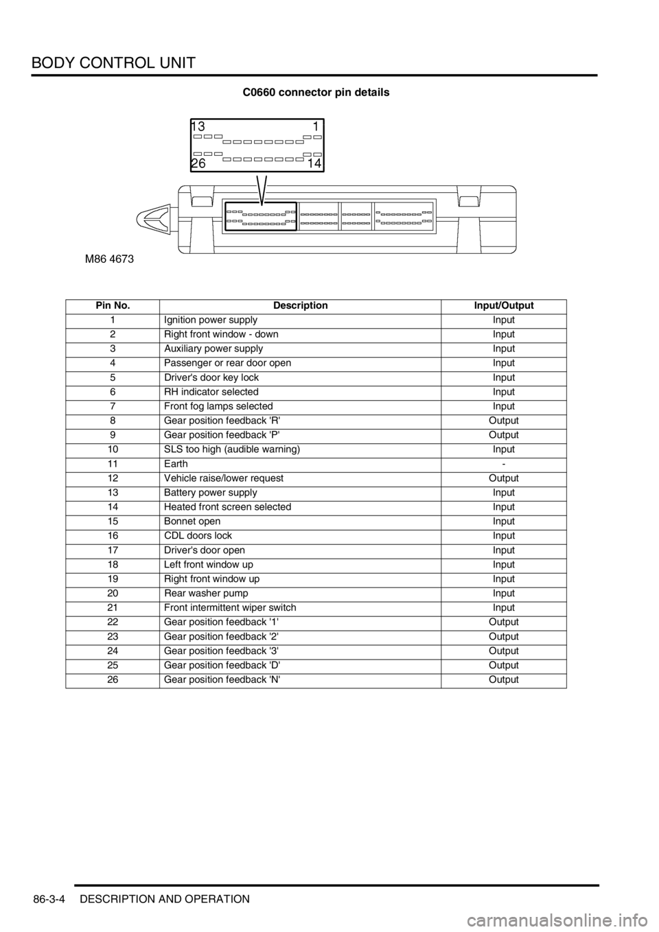
C0660 connector pin details
Pin No. Description Input/Output
1 Ignition power supply Input
2 Right front window - down Input
3 Auxiliary power supply Input
4 Passenger or rear door open Input
5 Driver's door key lock Input
6 RH indicator selected Input
7 Front fog lamps selected Input
8 Gear position feedback 'R' Output
9 Gear position feedback 'P' Output
10 SLS too high (audible warning) Input
11 Earth -
12 Vehicle raise/lower request Output
13 Battery power supply Input
14 Heated front screen selected Input
15 Bonnet open Input
16 CDL doors lock Input
17 Driver's door open Input
18 Left front window up Input
19 Right front window up Input
20 Rear washer pump Input
21 Front intermittent wiper switch Input
22 Gear position feedback '1' Output
23 Gear position feedback '2' Output
24 Gear position feedback '3' Output
25 Gear position feedback 'D' Output
26 Gear position feedback 'N' Output