1999 LAND ROVER DISCOVERY bonnet
[x] Cancel search: bonnetPage 1341 of 1529
ALARM SYSTEM AND HORN
86-4-18 DESCRIPTION AND OPERATION
Internal locking
Internal locking allows the doors to be locked / unlocked from a central position using switches on the instrument
panel. The internal unlock switch will not operate if the vehicle is super locked.
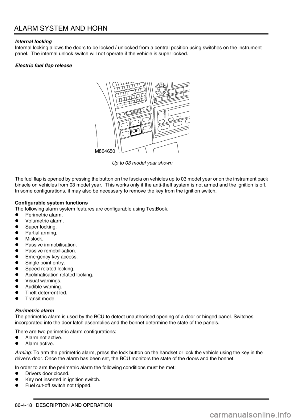
Electric fuel flap release
Up to 03 model year shown
The fuel flap is opened by pressing the button on the fascia on vehicles up to 03 model year or on the instrument pack
binacle on vehicles from 03 model year. This works only if the anti-theft system is not armed and the ignition is off.
In some configurations, it may also be necessary to remove the key from the ignition switch.
Configurable system functions
The following alarm system features are configurable using TestBook.
lPerimetric alarm.
lVolumetric alarm.
lSuper locking.
lPartial arming.
lMislock.
lPassive immobilisation.
lPassive remobilisation.
lEmergency key access.
lSingle point entry.
lSpeed related locking.
lAcclimatisation related locking.
lVisual warnings.
lAudible warning.
lTheft deterrent led.
lTransit mode.
Perimetric alarm
The perimetric alarm is used by the BCU to detect unauthorised opening of a door or hinged panel. Switches
incorporated into the door latch assemblies and the bonnet determine the state of the panels.
There are two perimetric alarm configurations:
lAlarm not active.
lAlarm active.
Arming: To arm the perimetric alarm, press the lock button on the handset or lock the vehicle using the key in the
driver's door. Once the alarm has been set, the BCU monitors the state of the doors and the bonnet.
In order to arm the perimetric alarm the following conditions must be met:
lDrivers door closed.
lKey not inserted in ignition switch.
lFuel cut-off switch not tripped.
Page 1342 of 1529

ALARM SYSTEM AND HORN
DESCRIPTION AND OPERATION 86-4-19
Disarming: To prevent the alarm from triggering when entering the vehicle, the alarm system must be disarmed with
the key or the handset.
There are two perimetric alarm disarming configurations:
lAlways disarm with key.
lOnly disarm with key if locked with key.
The perimetric alarm can be disarmed by unlocking the vehicle with the handset or by using the key in the driver's
door lock, depending on system configuration.
NOTE: The “only disarm with key if locked with key” configuration prevents the alarm from being disarmed by
unlocking the vehicle with the handset if the vehicle has been locked by the key. In this situation the Emergency Key
Access (EKA) code must be entered to disarm the alarm.
In order for the alarm to trigger, the following conditions must be met:
lPerimetric alarm armed.
lBonnet or door opened.
Once triggered, the alarm will remain triggered for 30 seconds before resetting.
Volumetric alarm
The volumetric alarm is used by the BCU to detect movement within the vehicle. This allows the alarm to be triggered
if a window is smashed in an attempt to gain access to the vehicle.
There are two volumetric alarm configurations:
lVolumetric alarm not active.
lVolumetric alarm active.
Two sensors, which transmit and receive ultrasonic signals, detect movement within the vehicle. Theses sensors
detect any change in air movement within the vehicle and then supply the BCU a signal to activate the alarm. Fifteen
seconds after the vehicle is locked with the handset or the key the volumetric alarm is armed. This delay is
incorporated into the BCU software to prevent accidental or nuisance triggering of the alarm.
In order to arm the volumetric alarm, the following conditions must be met:
lDriver's door closed.
lKey not inserted in ignition.
lFuel cut-off switch not tripped.
To prevent the alarm from triggering when entering the vehicle, the alarm system must be disarmed with the key or
the handset.
There are two volumetric alarm disarming configurations:
lAlways disarm with key.
lOnly disarm with key if locked with key.
The volumetric alarm can be disarmed by unlocking the driver's door with the key or the handset, depending on
system configuration.
NOTE: The “only disarm with key if locked with key” configuration prevents the alarm from being disarmed by
unlocking the vehicle with the handset if the vehicle has been locked by the key. In this situation the EKA code must
be entered to disarm the alarm.
In order for the alarm to trigger, the following conditions must be met:
lVolumetric alarm armed.
lVolumetric sensors triggered.
Once triggered, the alarm will remain triggered for 30 seconds before resetting.
Page 1343 of 1529

ALARM SYSTEM AND HORN
86-4-20 DESCRIPTION AND OPERATION
Super locking
Super locking prevents the use of the interior door handles to unlock and open the vehicle doors. This prevents the
doors from being opened if the window be smashed in an attempt to gain access to the vehicle.
There are four configurations for super locking:
lNo super locking.
lSuper locking on single handset press only (no key activated super locking).
lSuper locking on single handset press or single key turn.
lSuper locking on double handset press or double key turn.
To super lock, press the lock button on the handset once or twice within one second depending on system
configuration. In some configurations, it is also possible to super lock the vehicle using the key in the driver's door.
This also may require one or two turns of the key in the lock direction. If two turns of the key are required to activate
super locking, the two turns must occur within one second of each other.
In order to super lock the vehicle, the following conditions must be met:
lAll door are closed.
lThe ignition is off.
lThe fuel cut-off switch is not tripped.
Partial arming
Partial arming allows protection of as much of the vehicle as possible if the alarm is armed with one or more doors or
the bonnet open.
Partial arming allows the vehicle alarm to be armed even if the following conditions exist. When the bonnet or door is
closed, the BCU activates the perimetric alarm and the volumetric alarm after 15 seconds have elapsed:
lThe bonnet is not closed: If the bonnet is open when the alarm is armed, the BCU activates super locking and
volumetric sensing. In this condition, the alarm enters a partially armed state. All other functions of the alarm are
active and the BCU monitors the bonnet for a change of state. If the bonnet closes, the system is completely
armed.
lThe passenger door, a rear door or the tail door is not closed: If a door is open when the alarm is armed, the BCU
does not activate super locking or volumetric sensing. In this condition the alarm enters a partially armed state.
All other alarm functions are armed and the BCU monitors the open door. If the door closes volumetric sensing
and super locking become active.
lFailure of a door latch switch: If a short circuit in the door latch switch occurs, the BCU presumes the door is not
closed. In this situation the BCU does not activate super locking or volumetric sensing. All other alarm functions
are armed.
lDamaged wiring harness: If a short circuit in the wiring harness for the door latch switch occurs, the BCU
presumes the door is not closed and does not activate super locking or volumetric sensing; all other alarm
functions are armed. If an open circuit in the wiring harness for the door latch switch occurs, the BCU presumes
the door is closed and arms the alarm as normal.
Mislock
Mislock alerts the driver that a failed attempt has been made to lock the vehicle because of the doors or the bonnet
not being fully closed.
There are six audible configurations for mislock:
lNo audible warning.
lAlarm sounder.
lVehicle horn.
lAlarm sounder and vehicle horn.
lBBUS.
lAlarm sounder, vehicle horn and BBUS.
When a failed attempt has been made to lock the vehicle, the audible warning device is switched on for 50 ms and
off for 200 ms. The BCU allows the audible warning device to operate 3 times.
Page 1350 of 1529
ALARM SYSTEM AND HORN
REPAIR 86-4-27
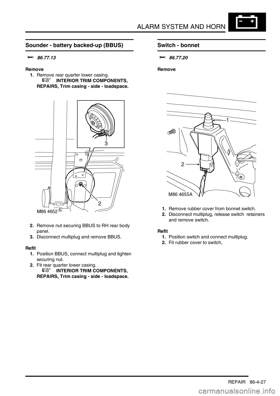
Sounder - battery backed-up (BBUS)
$% 86.77.13
Remove
1.Remove rear quarter lower casing.
+ INTERIOR TRIM COMPONENTS,
REPAIRS, Trim casing - side - loadspace.
2.Remove nut securing BBUS to RH rear body
panel.
3.Disconnect multiplug and remove BBUS.
Refit
1.Position BBUS, connect multiplug and tighten
securing nut.
2.Fit rear quarter lower casing.
+ INTERIOR TRIM COMPONENTS,
REPAIRS, Trim casing - side - loadspace.
Switch - bonnet
$% 86.77.20
Remove
1.Remove rubber cover from bonnet switch.
2.Disconnect multiplug, release switch retainers
and remove switch.
Refit
1.Position switch and connect multiplug.
2.Fit rubber cover to switch,
Page 1407 of 1529
HARNESSES
86-7-2 REPAIRS
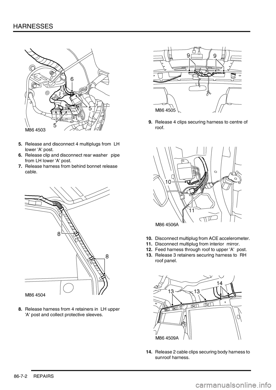
5.Release and disconnect 4 multiplugs from LH
lower 'A' post.
6.Release clip and disconnect rear washer pipe
from LH lower 'A' post.
7.Release harness from behind bonnet release
cable.
8.Release harness from 4 retainers in LH upper
'A' post and collect protective sleeves. 9.Release 4 clips securing harness to centre of
roof.
10.Disconnect multiplug from ACE accelerometer.
11.Disconnect multiplug from interior mirror.
12.Feed harness through roof to upper 'A' post.
13.Release 3 retainers securing harness to RH
roof panel.
14.Release 2 cable clips securing body harness to
sunroof harness.
Page 1412 of 1529

HARNESSES
REPAIRS 86-7-7
Refit
1.With assistance, position harness to air
conditioning ducting and secure with cable ties.
2.Secure harness to sunroof harness with cable
clips.
3.Connect multiplug to RF receiver.
4.Feed harness to LH and RH upper 'E' posts.
5.Feed harness through 'E' post to tail lamp and
rear bumper and secure with grommet.
6.Connect multiplug to fuel flap solenoid and
alarm sounder.
7.Position alarm sounder to rear quarter and
secure with nut to 9 Nm (7 lbf.ft).
8.Position both RH earth header to 'E' post and
tighten nut to 10 Nm (7 lbf.ft).
9.Feed tail door harness through 'E' post and
secure with grommet.
10.Position harness sleeve to outer edge of door
and pull harness through door.
11.Secure harness to tail door with clips.
12.Connect washer tube to rear of wiper arm.
13.Remove tape from draw string and secure to
CHMSL harness.
14.Draw harness through tail door and connect
Lucars to CHMSL.
15.Fit CHMSL cover and secure with screws.
16.Connect multiplug to door lock switch.
17.Connect Lucars to HRW.
18.Connect multiplug to rear wiper motor.
19.Connect multiplug to door latch.
20.Fit plastic sheet to tail door, ensuring it aligns
with witness marks.
21.Fit tail door trim casing.
+ DOORS, REPAIRS, Trim casing - tail
door.
22.Connect Lucar to radio aerial RH amplifier.
23.Secure harness to RH side of body with clips
and retainers.
24.Position both LH earth header to 'E' post and
tighten nut to 10 Nm (7 lbf.ft).
25.Connect multiplugs to both tail/flasher lamps
and secure harness to bumper with clips.
26.Fit both rear tail lamps.
+ LIGHTING, REPAIRS, Lamp - tail.
27.Secure harness to rear LH side of body with 6
cable clips.
28.Connect 2 Lucars to rear air conditioning unit.
29.Fit both luggage compartment trim casings.
+ INTERIOR TRIM COMPONENTS,
REPAIRS, Trim casing - side - loadspace.
30.Feed harness into position for rear interior light.
31.Connect Lucar to radio aerial LH amplifier.
32.Secure harness to body with cable ties clips
and retainers.
33.Secure air conditioning ducting to body with
rivets.
34.Feed harness to LH lower 'A' post. 35.Secure harness to LH side of body with cable
tie clips and retainers.
36.Connect and secure multiplugs to lower LH 'A'
post.
37.Feed harness through roof to centre.
38.Secure harness behind bonnet release cable.
39.Connect rear washer pipe at lower 'A' post and
secure with clip.
40.Secure harness to roof with clips.
41.Connect multiplug to interior mirror, ARC
accelerometer.
42.Position sound deadening panels and secure
with clips.
43.Fit headlining.
+ INTERIOR TRIM COMPONENTS,
REPAIRS, Headlining.
44.Fit fascia panel.
+ INTERIOR TRIM COMPONENTS,
REPAIRS, Fascia.
Page 1426 of 1529
HARNESSES
REPAIRS 86-7-21
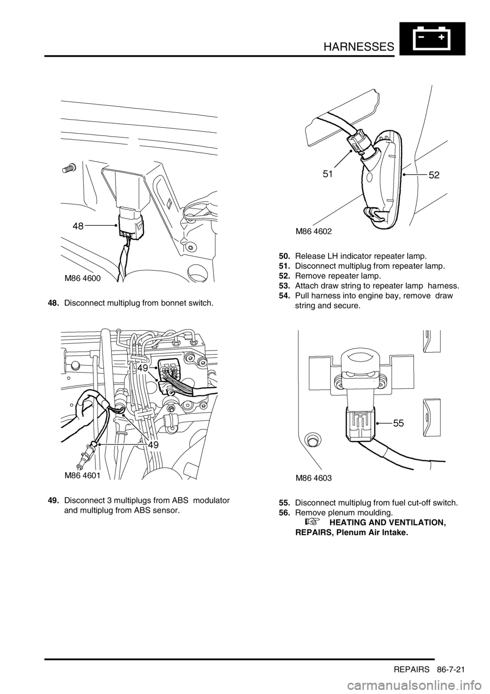
48.Disconnect multiplug from bonnet switch.
49.Disconnect 3 multiplugs from ABS modulator
and multiplug from ABS sensor. 50.Release LH indicator repeater lamp.
51.Disconnect multiplug from repeater lamp.
52.Remove repeater lamp.
53.Attach draw string to repeater lamp harness.
54.Pull harness into engine bay, remove draw
string and secure.
55.Disconnect multiplug from fuel cut-off switch.
56.Remove plenum moulding.
+ HEATING AND VENTILATION,
REPAIRS, Plenum Air Intake.
Page 1427 of 1529
HARNESSES
86-7-22 REPAIRS
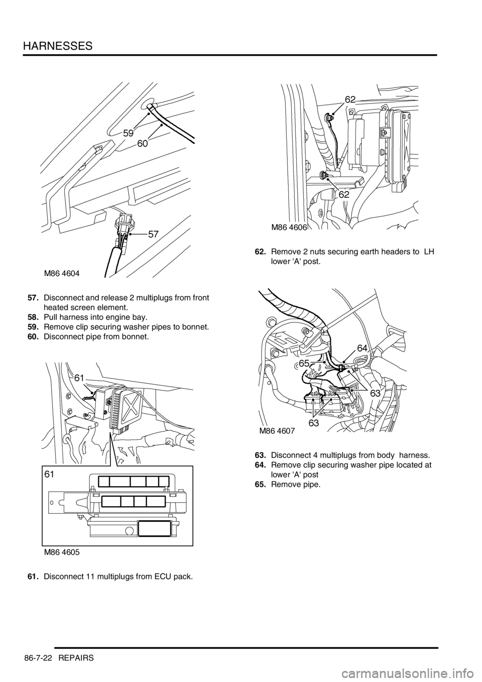
57.Disconnect and release 2 multiplugs from front
heated screen element.
58.Pull harness into engine bay.
59.Remove clip securing washer pipes to bonnet.
60.Disconnect pipe from bonnet.
61.Disconnect 11 multiplugs from ECU pack. 62.Remove 2 nuts securing earth headers to LH
lower 'A' post.
63.Disconnect 4 multiplugs from body harness.
64.Remove clip securing washer pipe located at
lower 'A' post
65.Remove pipe.