1999 LAND ROVER DISCOVERY turn signal
[x] Cancel search: turn signalPage 1376 of 1529

IN CAR ENTERTAINMENT
DESCRIPTION AND OPERATION 86-6-9
Inputs and outputs
The radio cassette player receives a mute signal from the telephone system if a call is received, when the call finishes
the mute is removed and the system resumes play. Inputs are also received from the steering wheel control system
(mid line and high line sytems). When the system is turned on, the high line systems radio cassette player:
lsends a 'power on enable' to the power amplifier
lsends an 'enable' signal to the radio headphone amplifiers.
On the high line system the radio cassette player also sends and receives signals from the CD-autochanger and rear
headphone amplifiers (if fitted). On high line systems the radio cassette player sends audio signals to the power
amplifier.
Remote radio steering wheel controls (midline and high line systems)
The remote radio control switch is located on the LH side of the steering wheel and is secured with two screws. The
wiring from the remote radio control switch plugs in to a connector that is part of the steering wheel rotary coupler.
Operation of the remote radio control switches allow the driver to control the ICE without releasing the steering wheel.
Volume, mode and selection functions can be carried out using the steering wheel mounted control switches. Control
inputs from the remote radio control switches are sent to the radio cassette player.
C0098
1 Telephone mute Input
2 Steering wheel remote radio controls Input
3 Steering wheel remote radio controls Output
4 Permanent battery feed Input
5 System enable Output
6 Illumination Input
7 Auxilary feed Input
8 Earth Input
C0921 (high line systems)
1 Radio headphone left channel Output +
2 Radio headphone right channel Output +
3 Telephone audio Input +
4 Radio headphone left channel Output -
5 Radio headphone right channel Output -
6 Telephone audio Input -
C0922 (high line systems)
7 Radio headphone active Input
8 I-BUS communications Input/Output
9 Audio amplifier spatial imaging enable Output
10 Radio headphone LH remote control Input
11 Radio headphone RH remote control Input
12 Headphone remote controls feed Output
C1354 (high line systems)
13 CD-autochanger audio left channel Input +
14 CD-autochanger audio right channel Input +
15 CD-autochanger audio earth Output
16 CD-autochanger audio left channel Input -
17 CD-autochanger audio right channel Input -
18 Not Used
19 CD-autochanger I-BUS communications link Input/Output
20 CD-autochanger permanent feed Output
Page 1377 of 1529

IN CAR ENTERTAINMENT
86-6-10 DESCRIPTION AND OPERATION
Aerial
On base and midline ICE systems an AM/FM aerial is built-in to the side window glass on the RH side of the vehicle.
An amplifier is located on the frame above the rear side widow behind the rear quarter trim, and is secured (and
earthed) with one bolt. Coaxial leads connect the aerial to the aerial amplifier and radio cassette. Power is supplied
from the auxilary relay in the engine compartment fuse box, through a fuse in the passenger compartment fusebox to
the amplifier.
On high line ICE systems two amplified aerials are built-in to the side window glass of the vehicle. The two aerials are
an AM/FM aerial on the RH side, and an FM aerial on the LH side. The amplifier for each aerial are located on the
frame above each rear side widow behind the rear quarter trim, and are each secured (and earthed) with one bolt.
Amplified aerials improve the reception quality, the FM aerial gives improved reception in areas of poor signal
(diversity) conditions in urban areas. A Power feed from the radio cassette player is connected to the amplified aerials,
power is available when the cassette player is operating. The aerials are connected to the radio cassette player by
two coaxial cables, a small plug connects the FM only aerial, a larger plug connects the AM/FM aerial.
Power amplifier (high line system)
The amplifier is located on a bracket under the LH front seat and is secured with three screws and washers. The
amplifier receives inputs from the radio, radio cassette player or (via the radio cassette player) the CD-autochanger.
Power for the amplifier is supplied from the passenger compartment fuse box. The amplifier will power up when an
enable logic signal is sent from the radio cassette, this signal is sent by the radio cassette when it is turned on.
CD-autochanger (high line system)
A CD-autochanger is located under the RH front seat, the unit is secured to brackets in the floor with four screws and
washers. A tray is used to hold each compact disk (CD), the loaded tray is then inserted in a magazine, the magazine
holds six trays and is then inserted into the CD-autochanger. A sliding cover protects the internal components of the
CD-autochanger from dirt entry through the magazine opening. An eject button located on the front of the CD-
autochanger can be used to release the magazine from the CD-autochanger. The sliding cover has to be opened
manually before the magazine eject button is pressed. The operation of the CD-autochanger is controlled by inputs
from the radio cassette, the control inputs can be from the radio cassette buttons, the remote radio controls or the rear
radio headphone amplifiers if they are fitted. The output from the CD-autochanger are connected to the radio cassette
player. The radio cassette player sends the outputs to the power amplifier. Power is supplied to the CD-autochanger
by a feed from the radio cassette player.
Radio headphone amplifiers (high line system)
The rear mounted radio headphone amplifiers are located in the lower rear quarter trim casing and are held in position
by a clip on the side of the headphone amplifier. Mode and function buttons are located on a control panel, the mode
button allows each of the rear seat passengers to independently select from the radio, tape or CD-autochanger. The
driver and the rear seat passengers can each listen to any of the audio devices they select. However the radio
cassette setting has overall priority e.g:
lIf the radio cassette is using a radio wave band (AM or FM), the headphone user will be able to select the cassette
tracks or CD-autochanger. The user will be able to listen to same radio band that is selected on the radio
cassette, but will not be able to change the station selected.
lIf the radio cassette has CD-autochanger selected, the headphone amplifiers will allow listening to the compact
disk but will not allow track changes. The headphone user will be able to select on all of the radio bands or
cassette tracks.
lIf the radio cassette has tape selected, the headphone amplifiers will allow listening to the tape but will not allow
track changes. The headphone user will be able to select all radio bands or CD's on the CD-autochanger.
If one headphone amplifier unit has control of the tape player, CD or radio, the other headphone amplifier will be able
to listen and be able to change tape tracks or radio bands. Other buttons allow a search seek function of radio band
or compact disk track, reversal of the tape, radio station and volume adjustment depending on the current operating
mode. If one radio headphone amplifier has control of the radio, tape or CD autochanger the other radio headphone
amplifier is able to change the track or radio band selected. A headphone socket with a glow ring is located on the
control panel. When a headphone is turned on , a 'headphone-module active' signal is sent to the radio cassette
player. The design incorporates panel illumination and a glow-ring to locate the socket in low light conditions. To
control the audio output from the radio headphone amplifiers, signals are sent to and received from the radio cassette
player.
Page 1385 of 1529

IN CAR ENTERTAINMENT
86-6-18 DESCRIPTION AND OPERATION
The console unit has three buttons which allow for minimum operation of the unit without using the handset:
lThe Stop/Eject button stops playback when pressed – 'Stop' appears on the LCD monitor as confirmation.
When the playback is stopped, a further press of the Stop/Eject button ejects the DVD or CD from the DVD
console – 'Eject' appears on the LCD monitor as confirmation.
lThe Play/Pause button begins play of the DVD or CD when pressed – 'Play' appears on the LCD monitor as
confirmation.
During play, pressing the Play/Pause button temporarily pauses the play – 'Pause' appears on the LCD monitor
as confirmation. A second press of the Play/Pause button resumes the play.
lThe Speaker button switches the DVD or CD audio to play through the vehicle audio speakers system. When the
CD is selected on the ICE head unit in the fascia, pressing the button allows the DVD or CD audio to play through
the vehicle audio speakers – 'Speaker On' appears on the LCD monitor. A second press of the button prevents
the DVD or CD audio playing through the vehicle audio speakers – 'Speaker Off' appears on the LCD monitor.
NOTE: These functions are also available from buttons on the remote handset.
Two sockets are provided on the left hand side of the unit and one socket on the right hand side of the unit for the use
of headphones with the overhead console unit. This allows the three occupants of the 2nd row seats to listen to the
DVD output using headphones. Occupants of the 3rd row seats can also listen to the DVD output using headphones
connected into the two radio/headphone amplifier units.
The console has three Phono sockets which allow for the use of an auxiliary video unit or video games console to be
connected to the system and use the LCD monitor for display. The sockets are colour coded for correct auxiliary input
connection as follows:
lRED – Right channel audio input
lWHITE – Left channel audio input
lYELLOW – Video input.
A slot is provided on the right hand side of the console for insertion of a DVD or CD into the console unit. The DVD
or CD can be inserted into the slot with the label side facing upwards. The DVD or CD is ejected from the slot when
the Stop/Eject button is pressed.
When the LCD monitor is in the lowered position, an infra-red receiver is exposed and receives transmitted signals
from the remote control handset. The receiver is located adjacent to the status LED which is illuminated when the
system is active.
The DVD player in the overhead console has an auto eject feature to protect the DVD or CD in the unit from damage
due to excessive heat. The status LED will flash to alert the user to this condition. If the temperature exceeds 70°C
(158°F), the DVD system automatically ejects the DVD or CD and shuts down, preventing further operation. When
the temperature in the vehicle has returned to 64°C (147°F) or less, press the 'Power' button on the handset or open
the LCD monitor to switch on the system.
Liquid Crystal Display (LCD) Monitor
The LCD monitor is suited for use with the in-car DVD system because of its compact, lightweight design and low
power consumption. The LCD monitor is a highly sophisticated unit and should be treated with care. Observe the
following precautions when using or handling the LCD monitor.
lDo not press on the monitor, this can distort the picture and cause permanent damage to the LCD panel.
lClean the LCD panel with a damp soft cloth with a mild household detergent if necessary. DO NOT use solvents,
commercial cleaners or anti-static sprays.
lDo not use the LCD in temperatures below 0°C (32°F) or above 80°C (176°F). If the vehicle is used in a cold
climate or in direct sunlight in a warm climate, the LCD monitor may not function correctly outside of the
temperatures stated. The picture may not be clear. This will not cause permanent damage to the monitor and the
picture should return to normal once the temperature is within the operating range as stated.
Page 1388 of 1529

IN CAR ENTERTAINMENT
DESCRIPTION AND OPERATION 86-6-21
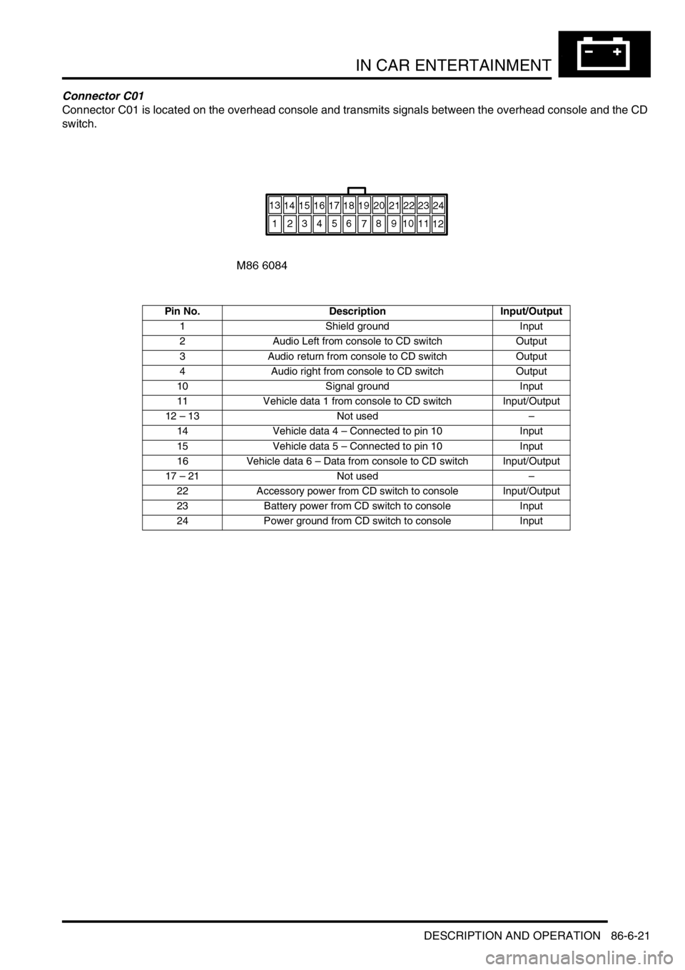
Connector C01
Connector C01 is located on the overhead console and transmits signals between the overhead console and the CD
switch.
Pin No. Description Input/Output
1 Shield ground Input
2 Audio Left from console to CD switch Output
3 Audio return from console to CD switch Output
4 Audio right from console to CD switch Output
10 Signal ground Input
11 Vehicle data 1 from console to CD switch Input/Output
12 – 13 Not used–
14 Vehicle data 4 – Connected to pin 10 Input
15 Vehicle data 5 – Connected to pin 10 Input
16 Vehicle data 6 – Data from console to CD switch Input/Output
17 – 21 Not used–
22 Accessory power from CD switch to console Input/Output
23 Battery power from CD switch to console Input
24 Power ground from CD switch to console Input
Page 1389 of 1529

IN CAR ENTERTAINMENT
86-6-22 DESCRIPTION AND OPERATION
Connector C04
Connector C04 is located on the CD switch and transmits signals between the CD switch and the overhead console.
Pin No. Description Input/Output
1 Shield ground Input
2 Audio left from console to CD switch Input
3 Audio return from console to CD switch Input
4 Audio right from console to CD switch Input
5 Vehicle data 5 – Connected from console to CD switch Input/Output
6 Vehicle data 1 – Connected between console and CD switch Input/Output
7 Vehicle data 6 – Connected between console and CD switch Input/Output
8 Accessory power from CD switch to console Input 12V
9 Battery power from CD switch to console Input 12V
10 Power ground from CD switch to console Input
Page 1457 of 1529

NAVIGATION SYSTEM
87-4 DESCRIPTION AND OPERATION
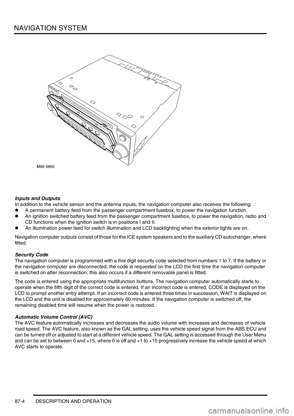
Inputs and Outputs
In addition to the vehicle sensor and the antenna inputs, the navigation computer also receives the following:
lA permanent battery feed from the passenger compartment fusebox, to power the navigation function.
lAn ignition switched battery feed from the passenger compartment fusebox, to power the navigation, radio and
CD functions when the ignition switch is in positions I and II.
lAn illumination power feed for switch illumination and LCD backlighting when the exterior lights are on.
Navigation computer outputs consist of those for the ICE system speakers and to the auxiliary CD autochanger, where
fitted.
Security Code
The navigation computer is programmed with a five digit security code selected from numbers 1 to 7. If the battery or
the navigation computer are disconnected, the code is requested on the LCD the first time the navigation computer
is switched on after reconnection; this also occurs if a different removable panel is fitted.
The code is entered using the appropriate multifunction buttons. The navigation computer automatically starts to
operate when the fifth digit of the correct code is entered. If an incorrect code is entered, CODE is displayed on the
LCD to prompt another entry attempt. If an incorrect code is entered three times in succession, WAIT is displayed on
the LCD and the unit is disabled for approximately 60 minutes. If the navigation computer is switched off, the
remaining disabled time will resume when the power is restored.
Automatic Volume Control (AVC)
The AVC feature automatically increases and decreases the audio volume with increases and decreases of vehicle
road speed. The AVC feature, also known as the GAL setting, uses the vehicle speed signal from the ABS ECU and
can be turned off or adjusted to start at a different vehicle speed. The GAL setting is accessed through the User Menu
and can be set to between 0 and +15, where 0 is off and +1 to +15 progressively increase the vehicle speed at which
AVC starts to operate.
Page 1461 of 1529

NAVIGATION SYSTEM
87-8 DESCRIPTION AND OPERATION
Calibration Routine
1Park the vehicle outside in an area clear of high buildings, trees etc.
NOTE: The more open the surrounding area is, the faster the system will acquire sufficient GPS satellite signals to
begin calibration. To minimise the calibration time, the vehicle should not be moved again until the calibration
ride.
2Turn the ignition switch to position II. If the navigation computer does not come on, press the navigation
computer ON button.
3If necessary, use the navigation computer multifunction buttons to enter the security code.
4Turn the ignition switch to position 0 and remove the ignition key.
5Press the navigation computer ON button.
6Call up the SENSORS screen on the LCD:
lIf the navigation CD-ROM has not been installed before, press and hold multifunction button 1 then press
multifunction button 10.
lIf the navigation CD-ROM has been installed before, use the garage menu as detailed above.
7Turn the LH rotary control to minimum volume.
8Wait for 30 minutes. If necessary, the vehicle can be left unattended and locked.
NOTE: Land Rover recommend a minimum of 30 minutes be allowed to elapse in order to ensure that only a short
distance need be driven to achieve calibration.
9After the 30 minutes have elapsed, ensure the navigation computer LCD shows a GPS almanac figure of 27 or
higher.
10Start the vehicle engine and allow to idle.
11Install the navigation CD-ROM.
12Wait until the navigation computer LCD prompts for a language to be selected. Turn the RH rotary control to
scroll through the options, highlight the required language and press the RH rotary control to select.
13The navigation computer LCD will prompt for a voice to be selected. Turn the RH rotary control to scroll through
the options, highlight the required voice and press the RH rotary control to select.
14Wait until the navigation computer LCD advises "language has been loaded OK". Press the RH rotary control to
confirm the language and voice selections.
15The navigation computer LCD will default to the CALIBRATION RIDE screen and should show the
CALIBRATION RIDE CAN START message. The GPS data and the road speed counter will also be shown.
16Drive the vehicle over a road route approximating that shown below (it is not necessary to copy the route
exactly). Calibration is complete when the navigation computer LCD switches to show DESTINATION & POI
and the satellite graphic. If all the pre calibration ride conditions were complied with, calibration is typically
achieved within 3 miles (5 km) and usually occurs when the vehicle returns to the start point. However,
calibration may be achieved earlier in the journey and, if it is, there is no need to complete the remainder of the
calibration route.
17After calibration is achieved, return to the dealership, park the vehicle and stop the engine.
18Turn the ignition switch to position I.
19Use the system settings menu to set the navigation computer to local time and the required units of measure:
aPress the Nav button.
bTurn the RH rotary control to scroll through the displayed menu, highlight TIME and press the RH rotary
control to select. Press the + or – multifunction button to adjust the time in 30 minute steps. Select the 24
hour clock and confirm by pressing the OK multifunction button.
cIf metric units of measure are required, go to step e) (the navigation computer defaults to metric units of
measure).
dIf Imperial units of measure are required, turn the RH rotary control to scroll through the displayed menu,
highlight MEASURING UNIT and press the RH rotary control to select. Turn the RH rotary control to
highlight IMPERIAL and press the RH rotary control to select.
ePress the Nav button to return to the destination menu.
20Calibration is complete. The navigation system is ready for use.
NOTE: The accuracy of the system will automatically be fine tuned when a further journey is made, but this is not
required as part of the calibration procedure.
NOTE: In European countries, the territory will have to be set the first time the navigation system is used, and the
first time a destination in another country is selected. The first time the navigation system is used or a destination
in another country is selected, a map is displayed with the default/current territory highlighted. To change the
territory: Press the RH rotary control to display the territory list; turn the RH rotary control to scroll through the
list and highlight the required territory; press the RH rotary control to confirm the selection.
Page 1469 of 1529

NAVIGATION SYSTEM
87-16 DESCRIPTION AND OPERATION
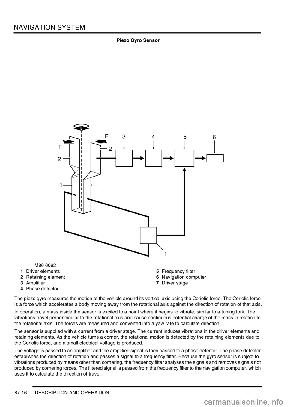
Piezo Gyro Sensor
1Driver elements
2Retaining element
3Amplifier
4Phase detector5Frequency filter
6Navigation computer
7Driver stage
The piezo gyro measures the motion of the vehicle around its vertical axis using the Coriolis force. The Coriolis force
is a force which accelerates a body moving away from the rotational axis against the direction of rotation of that axis.
In operation, a mass inside the sensor is excited to a point where it begins to vibrate, similar to a tuning fork. The
vibrations travel perpendicular to the rotational axis and cause continuous potential charge of the mass in relation to
the rotational axis. The forces are measured and converted into a yaw rate to calculate direction.
The sensor is supplied with a current from a driver stage. The current induces vibrations in the driver elements and
retaining elements. As the vehicle turns a corner, the rotational motion is detected by the retaining elements due to
the Coriolis force, and a small electrical voltage is produced.
The voltage is passed to an amplifier and the amplified signal is then passed to a phase detector. The phase detector
establishes the direction of rotation and passes a signal to a frequency filter. Because the gyro sensor is subject to
vibrations produced by means other than cornering, the frequency filter analyses the signals and removes signals not
produced by cornering forces. The filtered signal is passed from the frequency filter to the navigation computer, which
uses it to calculate the direction of travel.