Page 1474 of 1529
NAVIGATION SYSTEM
DESCRIPTION AND OPERATION 87-21
Basic Settings Menu
Service Mode
The service mode is accessed from the basic settings menu, by pushing and holding the menu switch until the service
mode menu is displayed. On the service mode menu, various checks can be selected using the rotary controller.
Pushing the menu switch again returns the system to the main menu.
The service mode has four main functions:
lTo check that components are fitted and to determine their hardware/software levels
lTo perform a quick 'health check' of the major input signals to the system
lTo check for correct operation of the control switches
lTo check the status of the GPS reception.
Service Mode Menu
SET
Units Language
D
km
110y 220y 550ymilesGB Other
Volume
Wp. radius
- 2
M86 6065
M86 6066
ON-BOARD MONITOR
NAVIGATION / GRAPHIC
ELEMENT
VIDEO MODULE
GPS
Service Mode
SENSOR TEST
Page 1478 of 1529

NAVIGATION SYSTEM
DESCRIPTION AND OPERATION 87-25
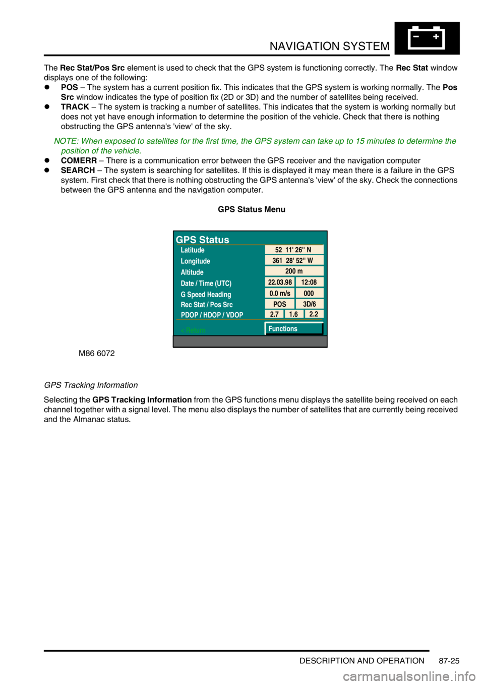
The Rec Stat/Pos Src element is used to check that the GPS system is functioning correctly. The Rec Stat window
displays one of the following:
lPOS – The system has a current position fix. This indicates that the GPS system is working normally. The Pos
Src window indicates the type of position fix (2D or 3D) and the number of satellites being received.
lTRACK – The system is tracking a number of satellites. This indicates that the system is working normally but
does not yet have enough information to determine the position of the vehicle. Check that there is nothing
obstructing the GPS antenna's 'view' of the sky.
NOTE: When exposed to satellites for the first time, the GPS system can take up to 15 minutes to determine the
position of the vehicle.
lCOMERR – There is a communication error between the GPS receiver and the navigation computer
lSEARCH – The system is searching for satellites. If this is displayed it may mean there is a failure in the GPS
system. First check that there is nothing obstructing the GPS antenna's 'view' of the sky. Check the connections
between the GPS antenna and the navigation computer.
GPS Status Menu
GPS Tracking Information
Selecting the GPS Tracking Information from the GPS functions menu displays the satellite being received on each
channel together with a signal level. The menu also displays the number of satellites that are currently being received
and the Almanac status.
M86 6072
GPS Status
Latitude
Longitude
Altitude
Date / Time (UTC)
G Speed Heading
Rec Stat / Pos Src
PDOP / HDOP / VDOP
< Return
200 m
22.03.98 12:08
0.0 m/s 000
POS3D/6
52 11' 26'' N
361 28' 52'' W
2.2
1.6 2.7
Functions
Page 1489 of 1529

INSTRUMENTS
88-6 DESCRIPTION AND OPERATION
The third warning lamp pack is located in the top right-hand side of the instrument pack and contains the following
warning lamps:
lSRS warning lamp.
lSLS off road mode warning lamp.
lTrailer warning lamp.
lGlow plug warning lamp.
lWater in fuel filter warning lamp.
lSeat belt warning lamp.
lTransmission high temperature warning lamp.
The fourth warning lamp pack is located underneath the tachometer of the instrument pack contains the following
warning lamps:
lOil pressure warning lamp.
lAlternator charge warning lamp.
lHDC fault warning lamp.
lSelf Levelling Suspension (SLS) warning lamp.
lActive Cornering Enhancement (ACE) warning lamp.
lGearbox manual/sport mode warning lamps.
The serial communication link is used to allow information to travel to and from the instrument pack, and it provides
the ability to configure the instrument pack to a specific market. It also allows the instrument pack to be controlled by
TestBook for diagnostics.
There are five market specific variants of the instrument pack:
lUnited Kingdom (UK).
lNorth American Specification (NAS).
lCanada.
lAustralia.
lRest Of the World (ROW), Gulf and Japan.
The main difference between the five markets is that the speedometer will indicate road speed in mph as major figures
and km/h as minor figures, km/h as major figures and mph as minor figures or km/h only.
When TestBook is used to diagnose the instrument pack it demands each of the dials and warning lamps to operate
in-turn so a visual check of their operation can be made.
CAUTION: The instrument pack must not be stored on its face side at any time. This is because the dials have
damping fluid within them to ensure smooth operation of the dials' indicator needles. This fluid will leak out.
Speedometer
The speedometer informs the driver of the current vehicle road speed. It has a Liquid Crystal Display (LCD) to show
odometer, trip meter and, on automatic gearbox models, the selected gear. The speedometer will not show speeds
of less than 1.5 mph (2.5 km/h).
There are three different market configurations:
lNAS and UK = mph as major figures km/h as minor figures.
lCanada = km/h as major figures mph as minor figures.
lROW and Australia = km/h only.
The Self Levelling and Anti-Lock Brake System (SLABS) ECU provides the signal input for the road speed. The signal
is at 8000 pulses per mile (1.6 kilometres).
Page 1492 of 1529

INSTRUMENTS
DESCRIPTION AND OPERATION 88-9
Fuel gauge
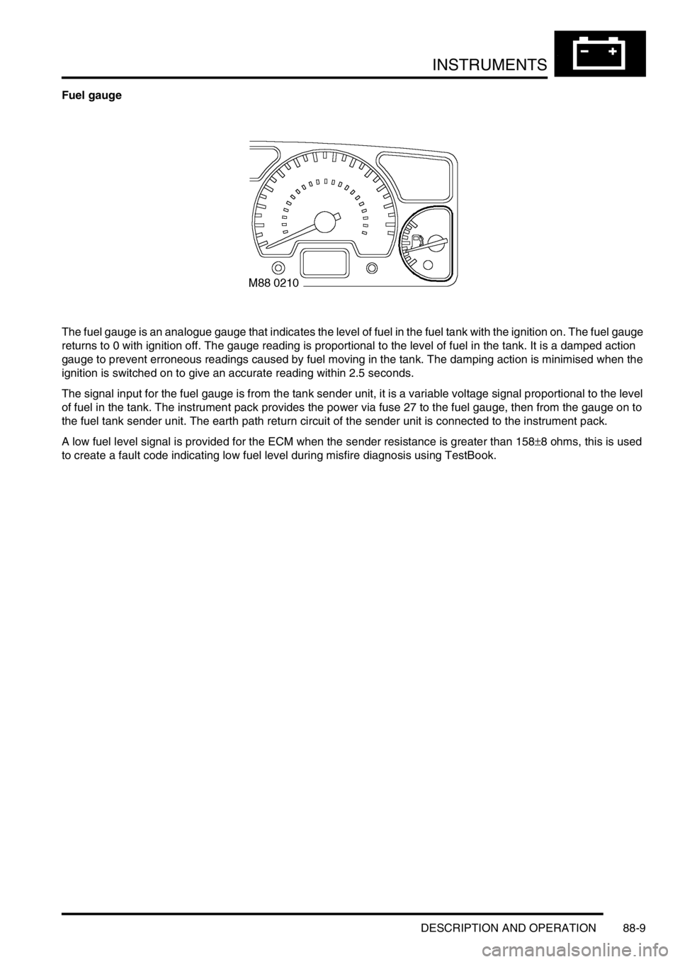
The fuel gauge is an analogue gauge that indicates the level of fuel in the fuel tank with the ignition on. The fuel gauge
returns to 0 with ignition off. The gauge reading is proportional to the level of fuel in the tank. It is a damped action
gauge to prevent erroneous readings caused by fuel moving in the tank. The damping action is minimised when the
ignition is switched on to give an accurate reading within 2.5 seconds.
The signal input for the fuel gauge is from the tank sender unit, it is a variable voltage signal proportional to the level
of fuel in the tank. The instrument pack provides the power via fuse 27 to the fuel gauge, then from the gauge on to
the fuel tank sender unit. The earth path return circuit of the sender unit is connected to the instrument pack.
A low fuel level signal is provided for the ECM when the sender resistance is greater than 158±8 ohms, this is used
to create a fault code indicating low fuel level during misfire diagnosis using TestBook.