1999 LAND ROVER DISCOVERY key
[x] Cancel search: keyPage 1049 of 1529
SUNROOF
76-6-18 REPAIRS
Motor - sunroof
$% 76.84.07
This procedure is applicable to the motor of both
sunroofs.
Remove
1.Gain access to the sunroof motor:
lFor front sunroof motor, remove front
stowage pocket.
+ INTERIOR TRIM COMPONENTS,
REPAIRS, Stowage pocket - front.
lFor rear sunroof motor, remove headlining.
+ INTERIOR TRIM COMPONENTS,
REPAIRS, Headlining.
CAUTION: The sunroof must be fully closed
before removing the sunroof motor.
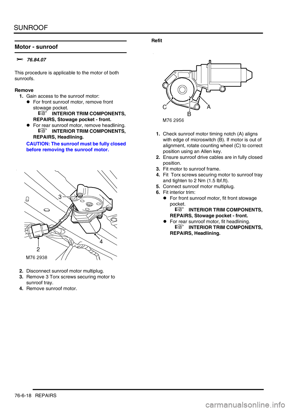
2.Disconnect sunroof motor multiplug.
3.Remove 3 Torx screws securing motor to
sunroof tray.
4.Remove sunroof motor. Refit
1.Check sunroof motor timing notch (A) aligns
with edge of microswitch (B). If motor is out of
alignment, rotate counting wheel (C) to correct
position using an Allen key.
2.Ensure sunroof drive cables are in fully closed
position.
3.Fit motor to sunroof frame.
4.Fit Torx screws securing motor to sunroof tray
and tighten to 2 Nm (1.5 lbf.ft).
5.Connect sunroof motor multiplug.
6.Fit interior trim:
lFor front sunroof motor, fit front stowage
pocket.
+ INTERIOR TRIM COMPONENTS,
REPAIRS, Stowage pocket - front.
lFor rear sunroof motor, fit headlining.
+ INTERIOR TRIM COMPONENTS,
REPAIRS, Headlining.
Page 1157 of 1529
PAINTING
77-5-2 PROCEDURES
Paint preparation
Paint refinishing
The following process must be adhered to for paint refinishing operations.
1Seal required exterior and interior seams with an approved seam sealer
+ BODY SEALING MATERIALS, MATERIALS AND APPLICATIONS, Approved materials.
2Repair any damage to underbody sealers
+ CORROSION PREVENTION AND SEALING, CORROSION PREVENTION, Corrosion prevention.
3Apply a two-pack paint refinishing system
4Apply cavity wax to all interior surfaces which have not received refinish paint
Paint repairs
Before carrying out paintwork repairs, clean the vehicle thoroughly using either a steam cleaner or high-pressure
washer.
Wash locally repaired areas using a mild water-mixable detergent and wipe them clean with solvent, immediately
before paint application.
Ensure that damaged paintwork which has led to exposed metal is abraded until the metal is clean, extending beyond
the area of the original damage. Treat the bare metal with an etch phosphate to remove all traces of rust and to provide
a key for new paint coats. Re-treat the affected area using either a separate acid-etch primer and two-pack surfacer
or an integrated etch primer/filler, and follow with a two-pack paint system. Treat those surfaces not receiving paint
using an approved cavity wax, following paint operations.
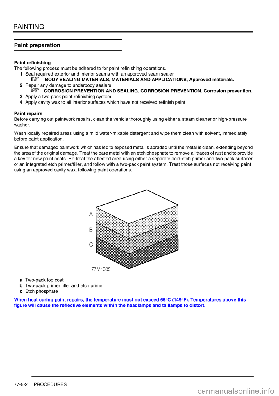
aTwo-pack top coat
bTwo-pack primer filler and etch primer
cEtch phosphate
When heat curing paint repairs, the temperature must not exceed 65°C (149°F). Temperatures above this
figure will cause the reflective elements within the headlamps and taillamps to distort.
Page 1274 of 1529
LIGHTING
ADJUSTMENTS 86-2-1
LIGHTING ADJUST ME NTS
Headlamps beam alignment - up to 03MY
$% 86.40.17
Check
1.Ensure vehicle is unladen and tyres are at
correct pressures.
2. Models with SLS: Ensure vehicle is at
standard ride height.
3. Models with headlamp levelling: Ensure
headlamp levelling switch is set to '0'.
4.Align suitable beam setting equipment to
headlamp.
5.Switch headlamps on and measure main beam
settings. Beam must be 1.4% below the
horizontal and parallel to the vehicle centre line.
If necessary, adjust headlamp to get correct
beam settings.
6.Align beam setting equipment to 2nd headlamp
and repeat check.
7.Switch off headlamps and remove beam setting
equipment.Adjust
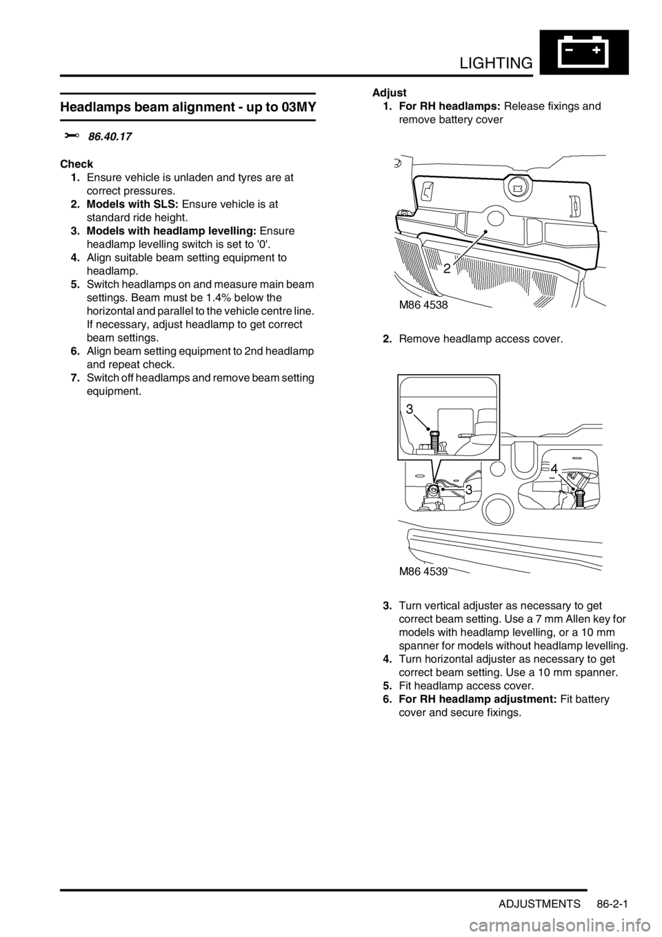
1. For RH headlamps: Release fixings and
remove battery cover
2.Remove headlamp access cover.
3.Turn vertical adjuster as necessary to get
correct beam setting. Use a 7 mm Allen key for
models with headlamp levelling, or a 10 mm
spanner for models without headlamp levelling.
4.Turn horizontal adjuster as necessary to get
correct beam setting. Use a 10 mm spanner.
5.Fit headlamp access cover.
6. For RH headlamp adjustment: Fit battery
cover and secure fixings.
Page 1286 of 1529
LIGHTING
REPAIRS 86-2-13
Switch - hazard warning
$% 86.65.50
Remove
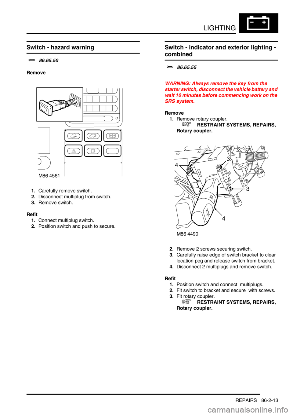
1.Carefully remove switch.
2.Disconnect multiplug from switch.
3.Remove switch.
Refit
1.Connect multiplug switch.
2.Position switch and push to secure.
Switch - indicator and exterior lighting -
combined
$% 86.65.55
WARNING: Always remove the key from the
starter switch, disconnect the vehicle battery and
wait 10 minutes before commencing work on the
SRS system.
Remove
1.Remove rotary coupler.
+ RESTRAINT SYSTEMS, REPAIRS,
Rotary coupler.
2.Remove 2 screws securing switch.
3.Carefully raise edge of switch bracket to clear
location peg and release switch from bracket.
4.Disconnect 2 multiplugs and remove switch.
Refit
1.Position switch and connect multiplugs.
2.Fit switch to bracket and secure with screws.
3.Fit rotary coupler.
+ RESTRAINT SYSTEMS, REPAIRS,
Rotary coupler.
Page 1288 of 1529

BODY CONTROL UNIT
DESCRIPTION AND OPERATION 86-3-1
BODY CONTROL UNIT DESCRIPTION AND OPERAT ION
Description
General
The Body Control Unit (BCU) is located behind the passenger glovebox and is connected to the main harness by four
connectors on its bottom edge and an additional connector located on the side of the BCU casing. Mounting the BCU
behind the fascia makes it reasonably inaccessible for intruders to disable the anti-theft system.
The BCU uses solid-state microprocessor control to perform logical operations and timing functions for a variety of
the vehicle's electrically operated systems, these include:
lDoor locking.
lAnti-theft alarm and immobilisation system.
lExterior lighting including direction indicators and hazard warning lamps.
lCourtesy lighting.
lWipers and washers.
lElectric windows and sunroof.
lHeated windows.
The BCU also communicates with several other electronically controlled systems such as the EAT ECU and SLABS
ECU and also has a datalink between the Intelligent Driver Module (IDM) and the instrument pack. The datalink is a
low speed bus capable of transmitting and receiving messages at a data rate of 10,400 bits per second. Additional
inputs and outputs to peripheral devices are included which are necessary for determining vehicle status for particular
logical operations e.g. crank, ignition key inserted, fuel flap enable etc.
The BCU receives its power supply from the engine compartment fuse box, and is protected by a 10 A fuse.
The BCU communicates with the IDM to provide the control signals to perform power switching operations in
conjunction with dedicated relays.
IDM
The IDM is integrated into the passenger compartment fuse box, which is mounted behind the fascia below the
steering column. There are no harnesses between the fuse box and the IDM. The IDM performs the power switching
operations for several of the vehicle's electrical systems.
The IDM communicates with the BCU and the instrument pack via a serial interface. If the BCU or the IDM is replaced,
the communications link between the two units has to be re-established. This can be done either by switching on the
ignition and leaving it on for five minutes, or by using TestBook. The vehicle immobilisation will remain active until the
communications link between the BCU and IDM has been re-established.
Transit mode
To prevent excessive battery drain during transit to overseas markets, the vehicle is placed in a transit mode. The
following functions are disabled when the vehicle is in transit mode:
lVolumetric sensors.
lPassive immobilisation.
lImmobilisation of the vehicle by use of door lock.
lIgnition key interlock.
lElectric seat enable time-out with driver's door open.
Page 1289 of 1529

BODY CONTROL UNIT
86-3-2 DESCRIPTION AND OPERATION
Power supply
Battery supply to the BCU and the IDM is provided through a 10 A fuse located in the engine compartment fuse box.
The BCU unit receives an ignition switched power supply (ignition switch position II) input via a 10 A fuse in the
passenger compartment fuse box.
The BCU receives a signal when the ignition switch is turned to the crank position, it then supplies an earth path to
the starter relay coil, to enable the crank operation by supplying power through the starter relay contacts to the starter
motor.
Battery voltage is monitored and BCU operation will function normally between 8 and 18 volts. Between 5.7 and 8
volts the BCU is in the 'under volts' state. The status of the battery is used to determine which outputs may be driven.
If a voltage supply above 18 volts is experienced, outputs will not normally be driven except for those functions which
are required during cranking (robust immobilisation, antenna coil, crank enable relay and feed to gear position switch
contacts W, X, Y, Z). In the over voltage state the vehicle can be driven, but all other functions are disabled and
outputs are switched off (power windows, heated screen, direction indicators etc.).
All functions are disabled on power up until communications between the BCU and IDM have been established. If
communications cannot be established, operation will commence with degraded functionality.
Battery supply to the IDM is provided through the inertia switch and a 10 A fuse in the engine compartment fuse box.
If the inertia switch contacts are closed battery voltage is available at the IDM; if the inertia switch contacts are open
there is no battery supply to the IDM. The supply condition of the IDM is signalled to the BCU via the serial bus. If the
inertia switch is operated (contacts open) the change in state is detected by the BCU which unlocks the doors if the
ignition switch is in position II and the alarm is not set.
The BCU is earthed through a hard-wire connection.
Inputs and outputs
The BCU and IDM process inputs and provide the necessary outputs for control and operation of the vehicle's 'body'
systems.
BCU inputs
The BCU processes signals received from the following components:
lDoor latch switches.
lDriver's door key lock/ unlock switches.
lBonnet activated security system.
lVolumetric sensors.
lCentral Door Locking (CDL) switches.
lRemote transmitter (via receiver unit).
lInertia fuel cut-off switch.
lIgnition switch.
lFuel flap release switch.
The input voltages (V
in) for BCU digital signals are defined as follows:
lLogic 1 when V
in ≥ 6V.
lLogic 0 when V
in ≤ 2V.
BCU input voltages between 2 and 6 volts are indeterminate and cannot be guaranteed.
Analogue input voltages are measured as a ratio with respect to battery voltage.
Page 1291 of 1529
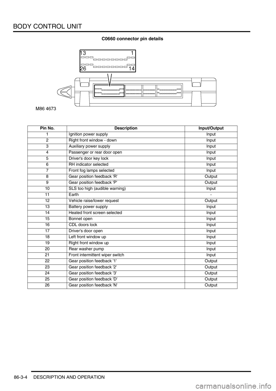
BODY CONTROL UNIT
86-3-4 DESCRIPTION AND OPERATION
C0660 connector pin details
Pin No. Description Input/Output
1 Ignition power supply Input
2 Right front window - down Input
3 Auxiliary power supply Input
4 Passenger or rear door open Input
5 Driver's door key lock Input
6 RH indicator selected Input
7 Front fog lamps selected Input
8 Gear position feedback 'R' Output
9 Gear position feedback 'P' Output
10 SLS too high (audible warning) Input
11 Earth -
12 Vehicle raise/lower request Output
13 Battery power supply Input
14 Heated front screen selected Input
15 Bonnet open Input
16 CDL doors lock Input
17 Driver's door open Input
18 Left front window up Input
19 Right front window up Input
20 Rear washer pump Input
21 Front intermittent wiper switch Input
22 Gear position feedback '1' Output
23 Gear position feedback '2' Output
24 Gear position feedback '3' Output
25 Gear position feedback 'D' Output
26 Gear position feedback 'N' Output
Page 1292 of 1529
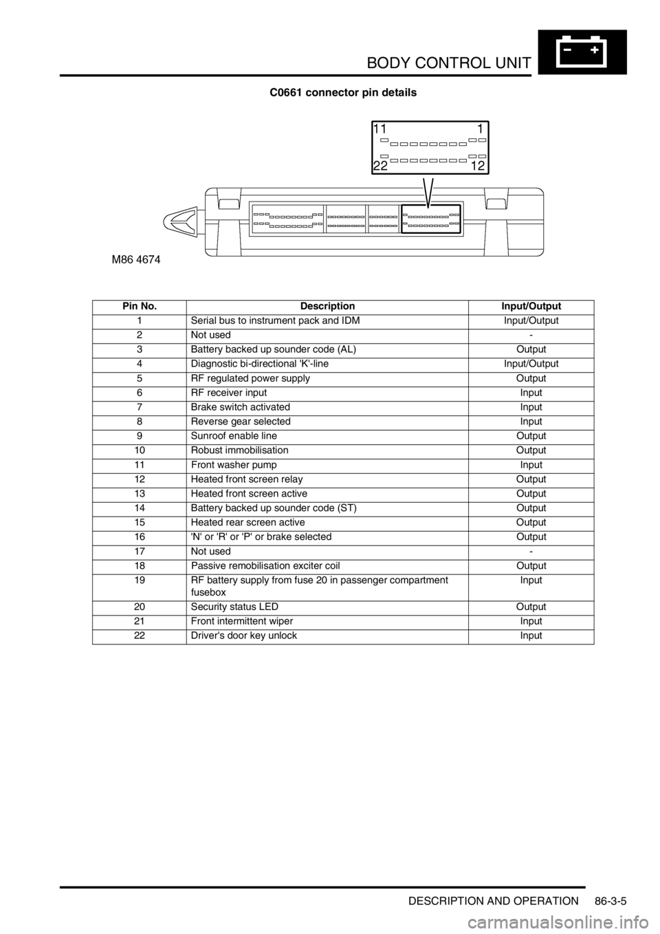
BODY CONTROL UNIT
DESCRIPTION AND OPERATION 86-3-5
C0661 connector pin details
Pin No. Description Input/Output
1 Serial bus to instrument pack and IDM Input/Output
2 Not used -
3 Battery backed up sounder code (AL) Output
4 Diagnostic bi-directional 'K'-line Input/Output
5 RF regulated power supply Output
6 RF receiver input Input
7 Brake switch activated Input
8 Reverse gear selected Input
9 Sunroof enable line Output
10 Robust immobilisation Output
11 Front washer pump Input
12 Heated front screen relay Output
13 Heated front screen active Output
14 Battery backed up sounder code (ST) Output
15 Heated rear screen active Output
16 'N' or 'R' or 'P' or brake selected Output
17 Not used -
18 Passive remobilisation exciter coil Output
19 RF battery supply from fuse 20 in passenger compartment
fuseboxInput
20 Security status LED Output
21 Front intermittent wiper Input
22 Driver's door key unlock Input