Page 1488 of 1529

INSTRUMENTS
DESCRIPTION AND OPERATION 88-5
Description
General
The instrument pack consists of four analogue dials, four warning lamp packs and a Liquid Crystal Display (LCD)
odometer.
The four dials are used to indicate:
lRoad speed.
lEngine speed.
lFuel tank level.
lEngine coolant temperature.
The dials are driven by a microprocessor from information received from the serial communication link. Information
input is received as either:
lDigital.
lAnalogue.
lPulse train.
lPulse Width Modulation (PWM).
The LCD provides information for:
lOdometer.
lTrip distance.
lSelected gear (on vehicles fitted with an automatic gearbox).
A trip reset button is provided to zero the trip display, this button also allows the selection of "miles" or "kilometres"
for the display. A photocell controls the illumination of the LCD, maintaining contrast of the display during ambient light
changes.
Within the four warning lamp packs there are 28 lamps. A long life bulb illuminates the high beam warning lamp and
the rest of the warning lamps are illuminated by Light Emitting Diodes (LED's). All warning lamp legends are invisible
until lit. When lit the symbols are illuminated on a black background.
The warning lamps illuminate in one of four colours. The colour indicates the level of importance to the driver, as
follows:
lRed = warning.
lAmber = caution.
lGreen = system operative.
lBlue = main beam operative.
The first warning lamp pack is located in the top left-hand side of the instrument pack and contains the following
warning lamps:
lTraction control warning lamp.
lTransfer box in neutral warning lamp.
lDifferential lock warning lamp
lOverspeed warning lamp (activated for gulf market only).
lBrake system warning lamp.
lHill Descent Control (HDC) information warning lamp.
lMalfunction Indicator Lamp (MIL)/ SERVICE ENGINE SOON warning lamp.
The second warning lamp pack is located in the centre of the instrument pack and contains the following warning
lamps:
lDirection indicator warning lamps.
lHigh beam warning lamp.
lAnti-lock brake system warning lamp.
Page 1491 of 1529
INSTRUMENTS
88-8 DESCRIPTION AND OPERATION
Tachometer
The tachometer is an integral part of the instrument pack. Located next to the speedometer. it displays engine speed
in revolutions per minute. It is an analogue gauge with a maximum reading of 6000 rev/min.
V8 and diesel variants use the same gauge.
The input for the tachometer is from the ECM. It is a digital signal at 2 pulses per engine revolution. When the ignition
is switched on with the engine not running, the ECM will generates pulses equivalent to 228 rev/min for diagnostic
purposes. The tachometer will not register a reading, as it only indicate engine speeds above 228 rev/min.
Page 1494 of 1529

INSTRUMENTS
DESCRIPTION AND OPERATION 88-11
Engine coolant temperature gauge
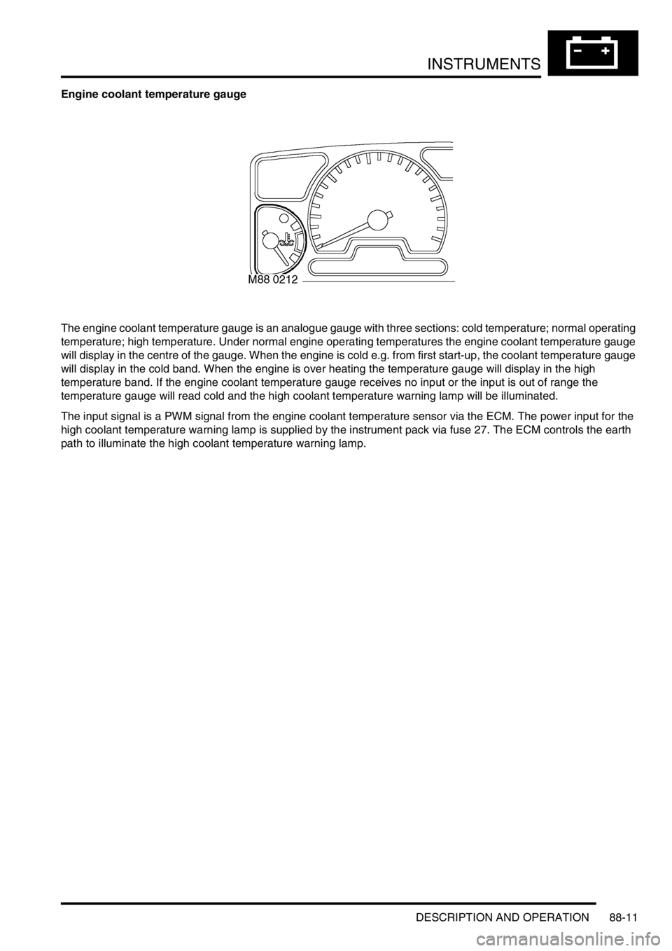
The engine coolant temperature gauge is an analogue gauge with three sections: cold temperature; normal operating
temperature; high temperature. Under normal engine operating temperatures the engine coolant temperature gauge
will display in the centre of the gauge. When the engine is cold e.g. from first start-up, the coolant temperature gauge
will display in the cold band. When the engine is over heating the temperature gauge will display in the high
temperature band. If the engine coolant temperature gauge receives no input or the input is out of range the
temperature gauge will read cold and the high coolant temperature warning lamp will be illuminated.
The input signal is a PWM signal from the engine coolant temperature sensor via the ECM. The power input for the
high coolant temperature warning lamp is supplied by the instrument pack via fuse 27. The ECM controls the earth
path to illuminate the high coolant temperature warning lamp.
Page 1495 of 1529

INSTRUMENTS
88-12 DESCRIPTION AND OPERATION
Malfunction Indicator Lamp (MIL)/ SERVICE ENGINE SOON warning lamp
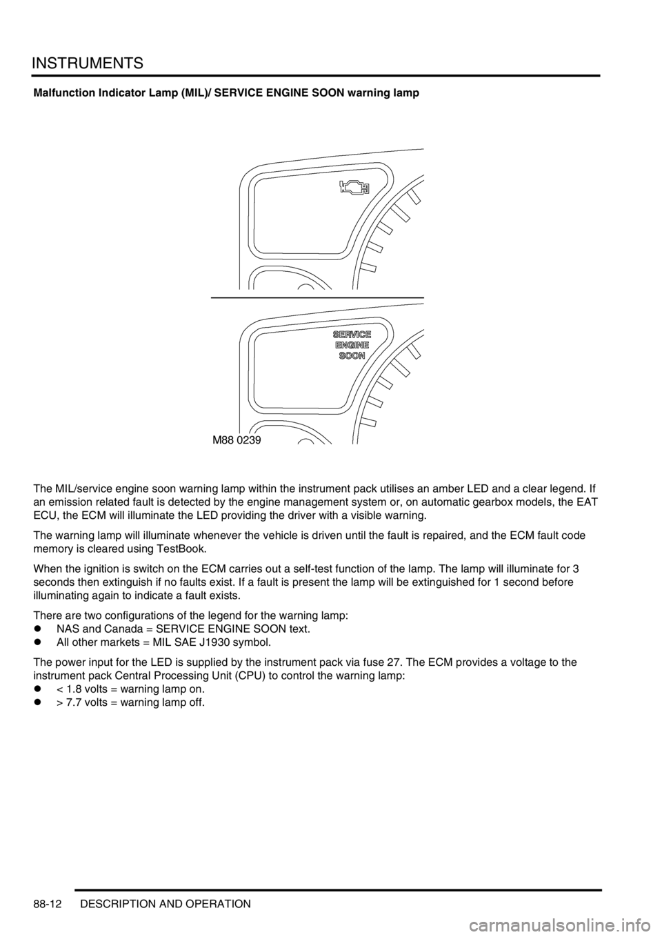
The MIL/service engine soon warning lamp within the instrument pack utilises an amber LED and a clear legend. If
an emission related fault is detected by the engine management system or, on automatic gearbox models, the EAT
ECU, the ECM will illuminate the LED providing the driver with a visible warning.
The warning lamp will illuminate whenever the vehicle is driven until the fault is repaired, and the ECM fault code
memory is cleared using TestBook.
When the ignition is switch on the ECM carries out a self-test function of the lamp. The lamp will illuminate for 3
seconds then extinguish if no faults exist. If a fault is present the lamp will be extinguished for 1 second before
illuminating again to indicate a fault exists.
There are two configurations of the legend for the warning lamp:
lNAS and Canada = SERVICE ENGINE SOON text.
lAll other markets = MIL SAE J1930 symbol.
The power input for the LED is supplied by the instrument pack via fuse 27. The ECM provides a voltage to the
instrument pack Central Processing Unit (CPU) to control the warning lamp:
l< 1.8 volts = warning lamp on.
l> 7.7 volts = warning lamp off.
Page 1502 of 1529

INSTRUMENTS
DESCRIPTION AND OPERATION 88-19
High engine coolant temperature warning lamp
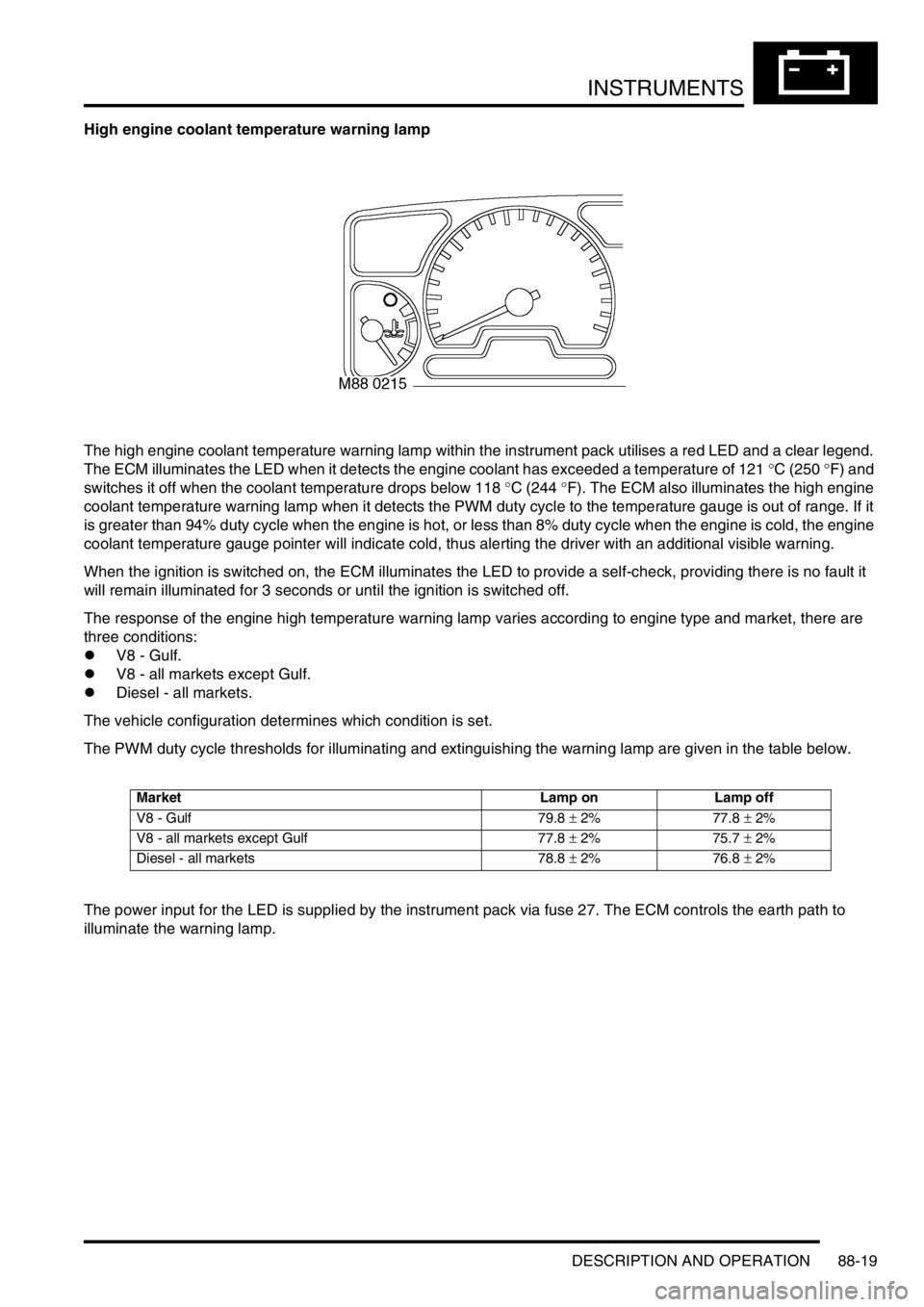
The high engine coolant temperature warning lamp within the instrument pack utilises a red LED and a clear legend.
The ECM illuminates the LED when it detects the engine coolant has exceeded a temperature of 121 °C (250 °F) and
switches it off when the coolant temperature drops below 118 °C (244 °F). The ECM also illuminates the high engine
coolant temperature warning lamp when it detects the PWM duty cycle to the temperature gauge is out of range. If it
is greater than 94% duty cycle when the engine is hot, or less than 8% duty cycle when the engine is cold, the engine
coolant temperature gauge pointer will indicate cold, thus alerting the driver with an additional visible warning.
When the ignition is switched on, the ECM illuminates the LED to provide a self-check, providing there is no fault it
will remain illuminated for 3 seconds or until the ignition is switched off.
The response of the engine high temperature warning lamp varies according to engine type and market, there are
three conditions:
lV8 - Gulf.
lV8 - all markets except Gulf.
lDiesel - all markets.
The vehicle configuration determines which condition is set.
The PWM duty cycle thresholds for illuminating and extinguishing the warning lamp are given in the table below.
The power input for the LED is supplied by the instrument pack via fuse 27. The ECM controls the earth path to
illuminate the warning lamp.
Market Lamp on Lamp off
V8 - Gulf 79.8 ± 2% 77.8 ± 2%
V8 - all markets except Gulf 77.8 ± 2% 75.7 ± 2%
Diesel - all markets 78.8 ± 2% 76.8 ± 2%
Page 1506 of 1529

INSTRUMENTS
DESCRIPTION AND OPERATION 88-23
Differential lock warning lamp (If fitted)
The differential lock is a device used for rolling road testing only on vehicles up to 03 model year. On vehicles from
03 model year, the differential is a driver selectable option which can also be used for off road driving. Refer to the
service procedures for details of rolling road testing on vehicles up to and from 03 model year.
CAUTION: Engage the differential lock when testing the vehicle on a two wheel rolling road. The propeller
shaft connecting the axle not on the rolling road must also be removed.
Differential lock warning lamp – vehicles up to 03 model year
The differential lock warning lamp within the instrument pack utilises a red LED and a clear legend. When the
differential lock is engaged, using the lever on the side of the transfer box, the differential lock switch is operated and
the warning lamp is switched on providing the driver with a visible warning.
When the differential lock is engaged, the warning lamp will be illuminated continuously when the ignition switch is in
position II.
Differential lock warning lamp – vehicles from 03 model year
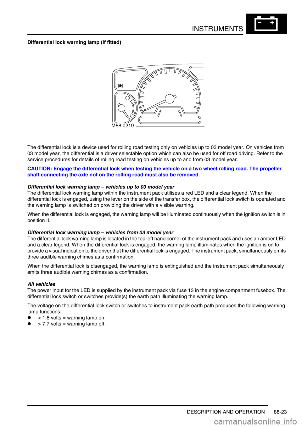
The differential lock warning lamp is located in the top left hand corner of the instrument pack and uses an amber LED
and a clear legend. When the differential lock is engaged, the warning lamp illuminates when the ignition is on to
provide a visual indication to the driver that the differential lock is engaged. The instrument pack, simultaneously emits
three audible warning chimes as a confirmation.
When the differential lock is disengaged, the warning lamp is extinguished and the instrument pack simultaneously
emits three audible warning chimes as a confirmation.
All vehicles
The power input for the LED is supplied by the instrument pack via fuse 13 in the engine compartment fusebox. The
differential lock switch or switches provide(s) the earth path illuminating the warning lamp.
The voltage on the differential lock switch or switches to instrument pack earth path produces the following warning
lamp functions:
l< 1.8 volts = warning lamp on.
l> 7.7 volts = warning lamp off.
Page 1511 of 1529
INSTRUMENTS
88-28 DESCRIPTION AND OPERATION
Glow plug warning lamp
The glow plug warning lamp within the instrument pack utilises an amber LED and a clear legend. On vehicles with
diesel engines the LED illuminates when the ECM operates the glow plugs. After a predetermined time calculated by
the ECM, dependent on engine temperature, the LED is switched off providing the driver with a visible warning that
the engine can be started.
The power input for the LED is supplied by the instrument pack via fuse 27. The ECM provides the earth path to
illuminate the warning lamp.
The voltage on the earth path from the ECM to the instrument pack is as follows:
l< 1.8 volts = warning lamp on.
l> 7.7 volts = warning lamp off.
Page 1512 of 1529
INSTRUMENTS
DESCRIPTION AND OPERATION 88-29
Water in fuel filter warning lamp
The water in fuel filter warning lamp within the instrument pack utilises an amber LED and a clear legend. On vehicles
with diesel engines the LED is illuminated when the water sensor detects water is present in the fuel filter, providing
the driver with a visible warning.
When the ignition is switched on, the instrument pack illuminates the LED to provide a self-check, providing there is
no water present in the fuel filter it will remain illuminated for 3 seconds or until the ignition is switched off.
The power input for the LED is supplied by the instrument pack via fuse 27. The water sensor provides the earth path
to illuminate the warning lamp. The voltage on the earth path from the sensor to the instrument pack is as follows:
l< 1.8 volts = warning lamp on.
l> 7.7 volts = warning lamp off.