1999 LAND ROVER DISCOVERY engine
[x] Cancel search: enginePage 1425 of 1529
HARNESSES
86-7-20 REPAIRS
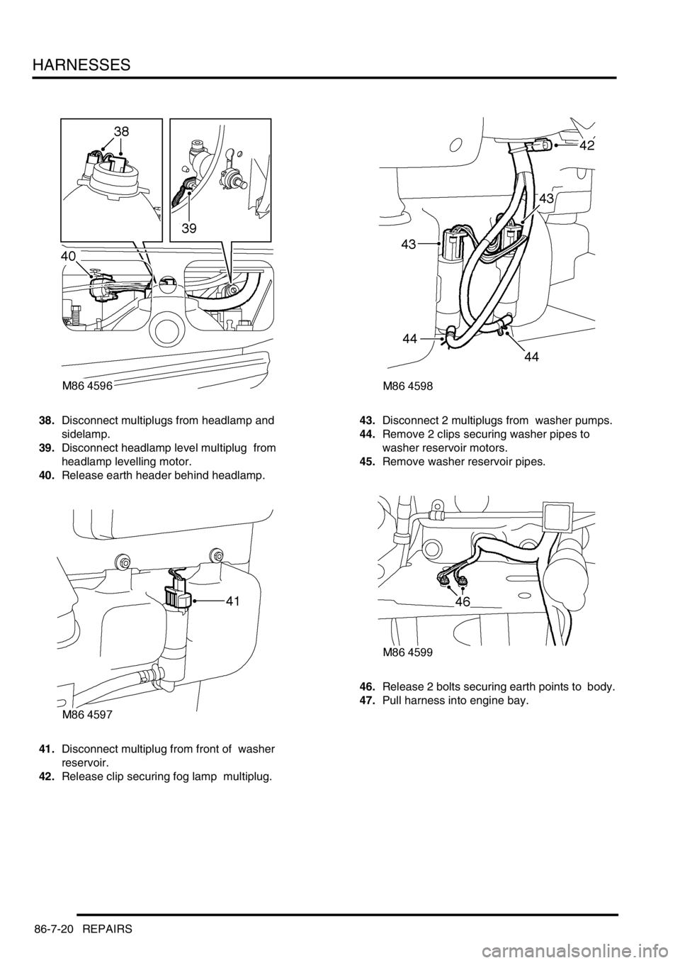
38.Disconnect multiplugs from headlamp and
sidelamp.
39.Disconnect headlamp level multiplug from
headlamp levelling motor.
40.Release earth header behind headlamp.
41.Disconnect multiplug from front of washer
reservoir.
42.Release clip securing fog lamp multiplug. 43.Disconnect 2 multiplugs from washer pumps.
44.Remove 2 clips securing washer pipes to
washer reservoir motors.
45.Remove washer reservoir pipes.
46.Release 2 bolts securing earth points to body.
47.Pull harness into engine bay.
Page 1426 of 1529
HARNESSES
REPAIRS 86-7-21
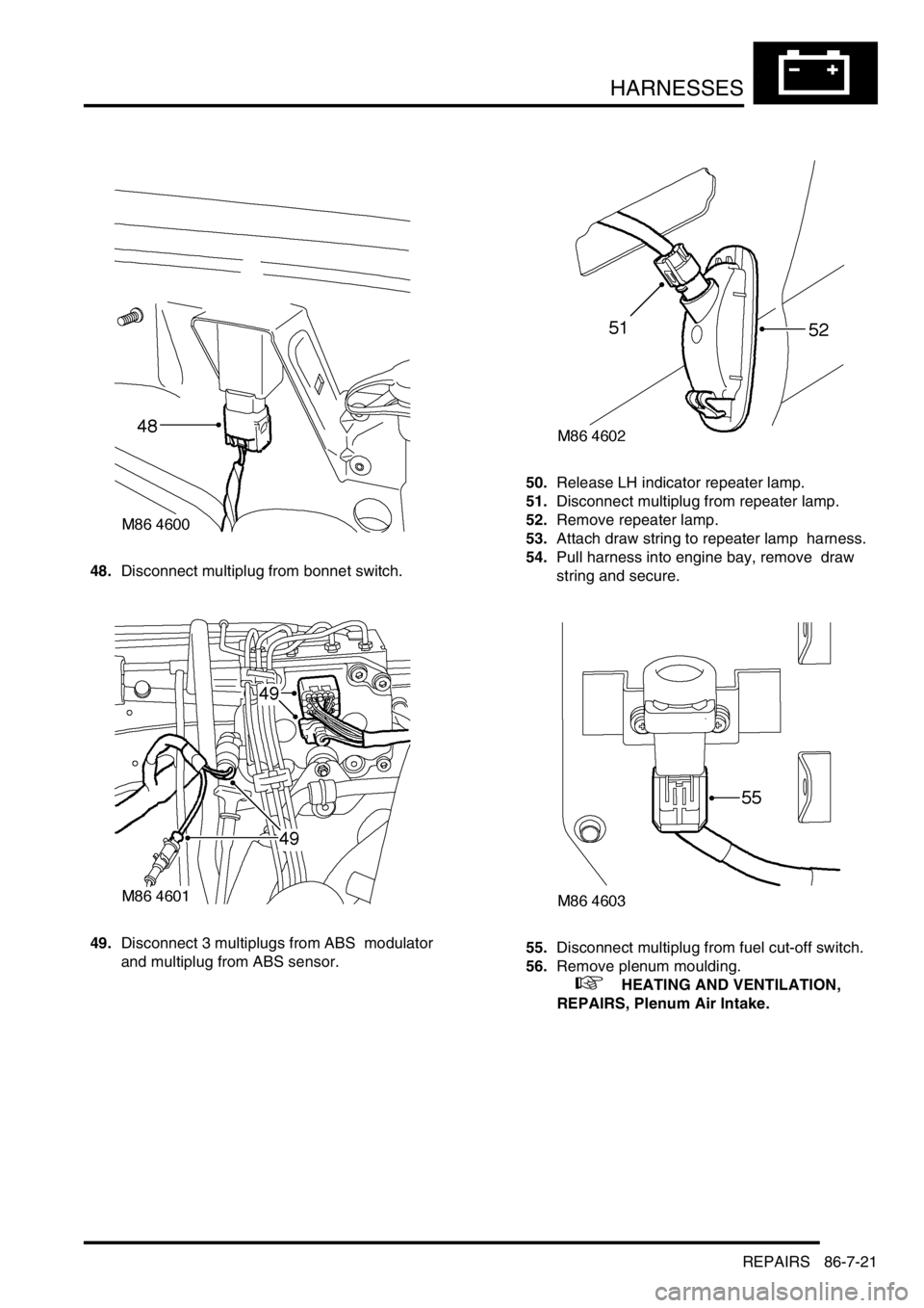
48.Disconnect multiplug from bonnet switch.
49.Disconnect 3 multiplugs from ABS modulator
and multiplug from ABS sensor. 50.Release LH indicator repeater lamp.
51.Disconnect multiplug from repeater lamp.
52.Remove repeater lamp.
53.Attach draw string to repeater lamp harness.
54.Pull harness into engine bay, remove draw
string and secure.
55.Disconnect multiplug from fuel cut-off switch.
56.Remove plenum moulding.
+ HEATING AND VENTILATION,
REPAIRS, Plenum Air Intake.
Page 1427 of 1529
HARNESSES
86-7-22 REPAIRS
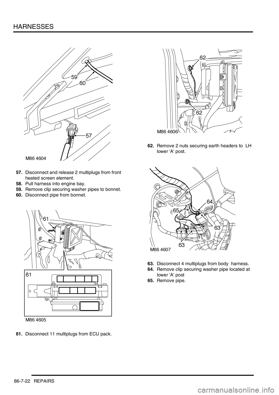
57.Disconnect and release 2 multiplugs from front
heated screen element.
58.Pull harness into engine bay.
59.Remove clip securing washer pipes to bonnet.
60.Disconnect pipe from bonnet.
61.Disconnect 11 multiplugs from ECU pack. 62.Remove 2 nuts securing earth headers to LH
lower 'A' post.
63.Disconnect 4 multiplugs from body harness.
64.Remove clip securing washer pipe located at
lower 'A' post
65.Remove pipe.
Page 1432 of 1529
HARNESSES
REPAIRS 86-7-27
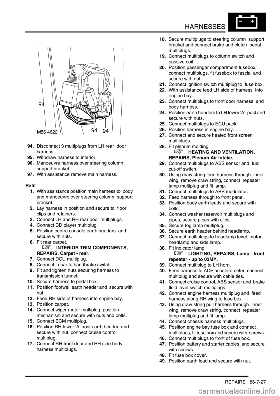
94.Disconnect 3 multiplugs from LH rear door
harness.
95.Withdraw harness to interior.
96.Manoeuvre harness over steering column
support bracket.
97.With assistance remove main harness.
Refit
1.With assistance position main harness to body
and manoeuvre over steering column support
bracket.
2.Lay harness in position and secure to floor
clips and retainers.
3.Connect LH and RH rear door multiplugs.
4.Connect CD player multiplug.
5.Position centre console earth headers and
secure with nuts.
6.Fit rear carpet.
+ INTERIOR TRIM COMPONENTS,
REPAIRS, Carpet - rear.
7.Connect DCU multiplug.
8.Connect Lucar to handbrake switch.
9.Fit and tighten nuts securing harness to
transmission tunnel.
10.Secure harness to pedal box.
11.Position footwell earth header and secure with
nut.
12.Feed RH side of harness into engine bay.
13.Position carpet.
14.Connect wiper motor multiplug, position
mechanism and secure with nuts and bolts.
15.Connect ECM multiplug.
16.Position RH lower 'A' post earth header and
secure with nut, connect cruise control
multiplug.
17.Connect RH front door and RH side body
harness multiplugs. 18.Secure multiplugs to steering column support
bracket and connect brake and clutch pedal
multiplugs.
19.Connect multiplugs to column switch and
passive coil.
20.Position passenger compartment fusebox,
connect multiplugs, fit fusebox to fascia and
secure with nut.
21.Connect ignition switch multiplug to fuse box.
22.With assistance feed LH side of harness into
engine bay.
23.Connect multiplugs to front door harness and
body harness.
24.Position earth headers to LH lower 'A' post and
secure with nuts.
25.Connect multiplugs to ECU pack.
26.Position harness in engine bay.
27.Connect and secure heated front screen
multiplugs.
28.Fit plenum molding.
+ HEATING AND VENTILATION,
REPAIRS, Plenum Air Intake.
29.Connect multiplugs to ABS sensor and fuel
cut-off switch.
30.Using draw string feed harness through inner
wing, remove draw string, connect repeater
lamp multiplug and fit lamp.
31.Connect multiplugs to ABS modulator.
32.Feed harness through to front panel.
33.Position body earth leads and secure with
bolts.
34.Connect washer reservoir multiplugs and
pipes, secure pipes with clips.
35.Secure fog lamp multiplug.
36.Secure earth header behind headlamp.
37.Connect multiplugs to headlamp level motor,
headlamp and side lamp.
38.Fit indicator lamp
+ LIGHTING, REPAIRS, Lamp - front
repeater - up to 03MY.
39.Connect multiplug to LH horn.
40.Feed harness to ACE accelerometer, connect
multiplug and secure with cable ties.
41.Connect cruise control, ABS sensor and brake
fluid level switch multiplugs.
42.Connect engine harness multiplug and feed
harness along RH wing to fuse box.
43.Using draw string pull harness through inner
wing, remove draw string, connect repeater
lamp multiplug and fit lamp.
44.Connect chassis harness multiplugs.
45.Position engine bay fuse box and connect
multiplugs, fit fuse box and secure with screws.
46.Connect multiplugs to front of fuse box.
47.Position battery and starter cables and secure
with screws.
48.Fit fuse box cover.
49.Position earth lead and secure with nut.
Page 1433 of 1529
HARNESSES
86-7-28 REPAIRS
50.Feed harness through to front panel.
51.Secure fog lamp multiplug.
52.Connect headlamp level motor, headlamp and
side lamp multiplugs.
53.Fit indicator lamp.
+ LIGHTING, REPAIRS, Lamp - front
repeater - up to 03MY.
54.Secure harness to RH front panel.
55.Connect cooling fan and horn multiplug.
56.Secure harness to lower support rail.
57.Connect receiver drier and air temperature
sensor multiplugs.
58.Fit front bumper.
+ EXTERIOR FITTINGS, REPAIRS,
Bumper assembly - front.
59.Fit battery tray.
60.Fit air filter assembly.
+ ENGINE MANAGEMENT SYSTEM -
V8, REPAIRS, Air cleaner assembly.
61.Position both lower 'A' post trims and secure
with studs.
62.Fit heater assembly.
+ HEATING AND VENTILATION,
REPAIRS, Heater assembly - models with
air conditioning.
+ HEATING AND VENTILATION,
REPAIRS, Heater assembly - models
without air conditioning.
Harness - main - DVD unit
$% 86.70.25
Remove
1.Remove battery cover and disconnect the
battery earth lead.
2.Remove CD switch box.
+ IN CAR ENTERTAINMENT,
REPAIRS, Switch box - CD/DVD player.
3.Remove DVD player unit.
+ IN CAR ENTERTAINMENT,
REPAIRS, DVD screen/player unit.
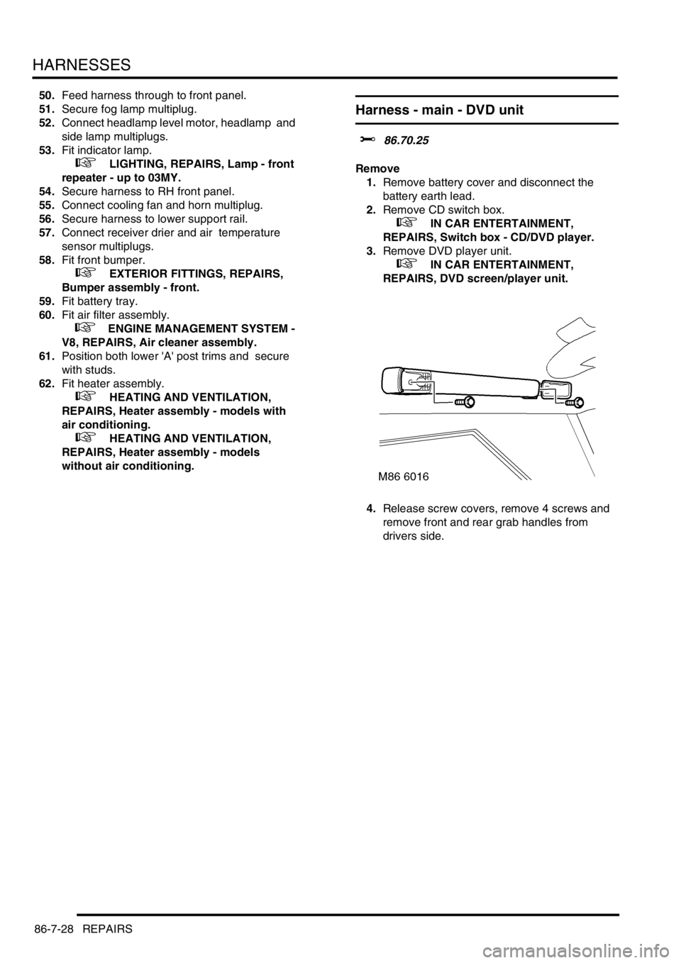
4.Release screw covers, remove 4 screws and
remove front and rear grab handles from
drivers side.
Page 1461 of 1529
NAVIGATION SYSTEM
87-8 DESCRIPTION AND OPERATION
Calibration Routine
1Park the vehicle outside in an area clear of high buildings, trees etc.
NOTE: The more open the surrounding area is, the faster the system will acquire sufficient GPS satellite signals to
begin calibration. To minimise the calibration time, the vehicle should not be moved again until the calibration
ride.
2Turn the ignition switch to position II. If the navigation computer does not come on, press the navigation
computer ON button.
3If necessary, use the navigation computer multifunction buttons to enter the security code.
4Turn the ignition switch to position 0 and remove the ignition key.
5Press the navigation computer ON button.
6Call up the SENSORS screen on the LCD:
lIf the navigation CD-ROM has not been installed before, press and hold multifunction button 1 then press
multifunction button 10.
lIf the navigation CD-ROM has been installed before, use the garage menu as detailed above.
7Turn the LH rotary control to minimum volume.
8Wait for 30 minutes. If necessary, the vehicle can be left unattended and locked.
NOTE: Land Rover recommend a minimum of 30 minutes be allowed to elapse in order to ensure that only a short
distance need be driven to achieve calibration.
9After the 30 minutes have elapsed, ensure the navigation computer LCD shows a GPS almanac figure of 27 or
higher.
10Start the vehicle engine and allow to idle.
11Install the navigation CD-ROM.
12Wait until the navigation computer LCD prompts for a language to be selected. Turn the RH rotary control to
scroll through the options, highlight the required language and press the RH rotary control to select.
13The navigation computer LCD will prompt for a voice to be selected. Turn the RH rotary control to scroll through
the options, highlight the required voice and press the RH rotary control to select.
14Wait until the navigation computer LCD advises "language has been loaded OK". Press the RH rotary control to
confirm the language and voice selections.
15The navigation computer LCD will default to the CALIBRATION RIDE screen and should show the
CALIBRATION RIDE CAN START message. The GPS data and the road speed counter will also be shown.
16Drive the vehicle over a road route approximating that shown below (it is not necessary to copy the route
exactly). Calibration is complete when the navigation computer LCD switches to show DESTINATION & POI
and the satellite graphic. If all the pre calibration ride conditions were complied with, calibration is typically
achieved within 3 miles (5 km) and usually occurs when the vehicle returns to the start point. However,
calibration may be achieved earlier in the journey and, if it is, there is no need to complete the remainder of the
calibration route.
17After calibration is achieved, return to the dealership, park the vehicle and stop the engine.
18Turn the ignition switch to position I.
19Use the system settings menu to set the navigation computer to local time and the required units of measure:
aPress the Nav button.
bTurn the RH rotary control to scroll through the displayed menu, highlight TIME and press the RH rotary
control to select. Press the + or – multifunction button to adjust the time in 30 minute steps. Select the 24
hour clock and confirm by pressing the OK multifunction button.
cIf metric units of measure are required, go to step e) (the navigation computer defaults to metric units of
measure).
dIf Imperial units of measure are required, turn the RH rotary control to scroll through the displayed menu,
highlight MEASURING UNIT and press the RH rotary control to select. Turn the RH rotary control to
highlight IMPERIAL and press the RH rotary control to select.
ePress the Nav button to return to the destination menu.
20Calibration is complete. The navigation system is ready for use.
NOTE: The accuracy of the system will automatically be fine tuned when a further journey is made, but this is not
required as part of the calibration procedure.
NOTE: In European countries, the territory will have to be set the first time the navigation system is used, and the
first time a destination in another country is selected. The first time the navigation system is used or a destination
in another country is selected, a map is displayed with the default/current territory highlighted. To change the
territory: Press the RH rotary control to display the territory list; turn the RH rotary control to scroll through the
list and highlight the required territory; press the RH rotary control to confirm the selection.
Page 1484 of 1529
INSTRUMENTS
DESCRIPTION AND OPERATION 88-1
INS TRUMENTS DESCRIPTION AND OPERAT ION
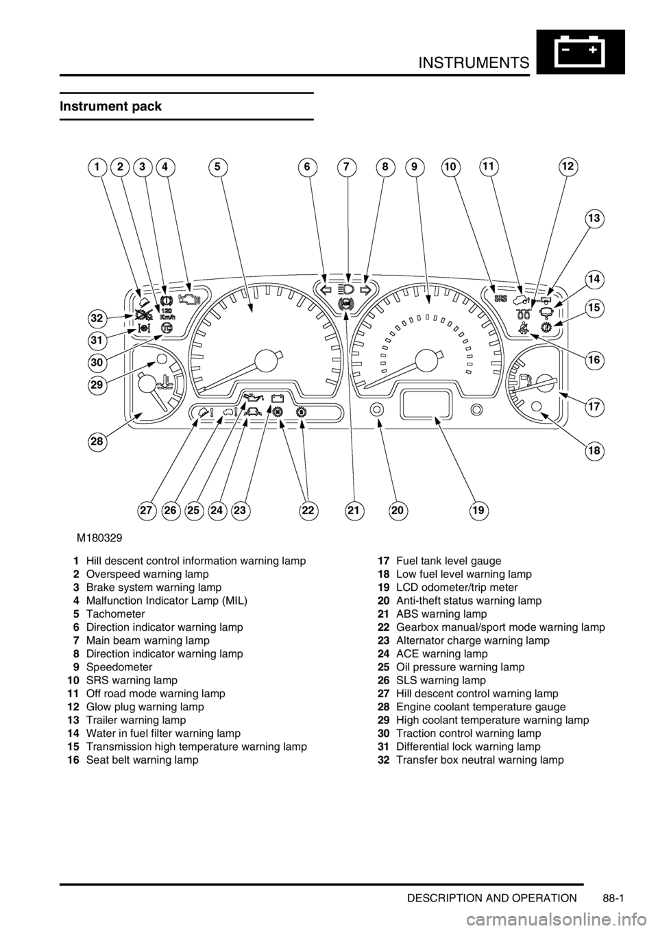
Instrument pack
1Hill descent control information warning lamp
2Overspeed warning lamp
3Brake system warning lamp
4Malfunction Indicator Lamp (MIL)
5Tachometer
6Direction indicator warning lamp
7Main beam warning lamp
8Direction indicator warning lamp
9Speedometer
10SRS warning lamp
11Off road mode warning lamp
12Glow plug warning lamp
13Trailer warning lamp
14Water in fuel filter warning lamp
15Transmission high temperature warning lamp
16Seat belt warning lamp17Fuel tank level gauge
18Low fuel level warning lamp
19LCD odometer/trip meter
20Anti-theft status warning lamp
21ABS warning lamp
22Gearbox manual/sport mode warning lamp
23Alternator charge warning lamp
24ACE warning lamp
25Oil pressure warning lamp
26SLS warning lamp
27Hill descent control warning lamp
28Engine coolant temperature gauge
29High coolant temperature warning lamp
30Traction control warning lamp
31Differential lock warning lamp
32Transfer box neutral warning lamp
Page 1485 of 1529
INSTRUMENTS
88-2 DESCRIPTION AND OPERATION
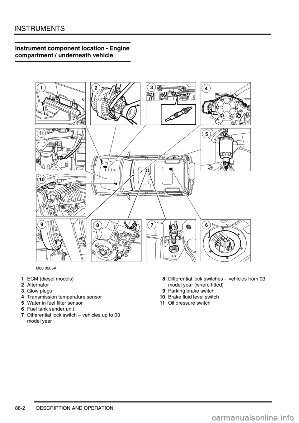
Instrument component location - Engine
compartment / underneath vehicle
1ECM (diesel models)
2Alternator
3Glow plugs
4Transmission temperature sensor
5Water in fuel filter sensor
6Fuel tank sender unit
7Differential lock switch – vehicles up to 03
model year8Differential lock switches – vehicles from 03
model year (where fitted)
9Parking brake switch
10Brake fluid level switch
11Oil pressure switch