1999 LAND ROVER DISCOVERY lock
[x] Cancel search: lockPage 1147 of 1529
CORROSION PREVENTION AND SEALING
77-4-14 SEALING
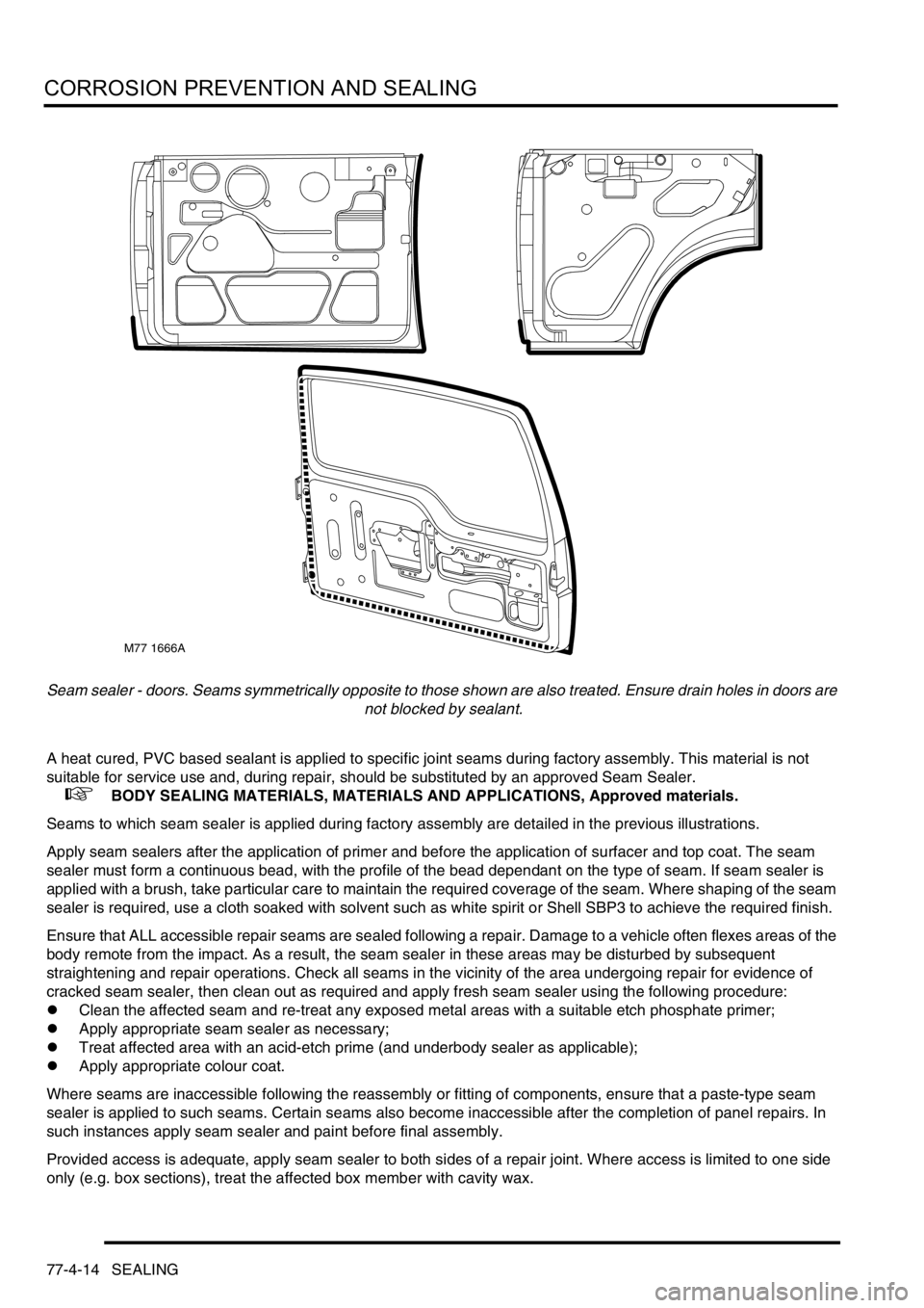
Seam sealer - doors. Seams symmetrically opposite to those shown are also treated. Ensure drain holes in doors are
not blocked by sealant.
A heat cured, PVC based sealant is applied to specific joint seams during factory assembly. This material is not
suitable for service use and, during repair, should be substituted by an approved Seam Sealer.
+ BODY SEALING MATERIALS, MATERIALS AND APPLICATIONS, Approved materials.
Seams to which seam sealer is applied during factory assembly are detailed in the previous illustrations.
Apply seam sealers after the application of primer and before the application of surfacer and top coat. The seam
sealer must form a continuous bead, with the profile of the bead dependant on the type of seam. If seam sealer is
applied with a brush, take particular care to maintain the required coverage of the seam. Where shaping of the seam
sealer is required, use a cloth soaked with solvent such as white spirit or Shell SBP3 to achieve the required finish.
Ensure that ALL accessible repair seams are sealed following a repair. Damage to a vehicle often flexes areas of the
body remote from the impact. As a result, the seam sealer in these areas may be disturbed by subsequent
straightening and repair operations. Check all seams in the vicinity of the area undergoing repair for evidence of
cracked seam sealer, then clean out as required and apply fresh seam sealer using the following procedure:
lClean the affected seam and re-treat any exposed metal areas with a suitable etch phosphate primer;
lApply appropriate seam sealer as necessary;
lTreat affected area with an acid-etch prime (and underbody sealer as applicable);
lApply appropriate colour coat.
Where seams are inaccessible following the reassembly or fitting of components, ensure that a paste-type seam
sealer is applied to such seams. Certain seams also become inaccessible after the completion of panel repairs. In
such instances apply seam sealer and paint before final assembly.
Provided access is adequate, apply seam sealer to both sides of a repair joint. Where access is limited to one side
only (e.g. box sections), treat the affected box member with cavity wax.
M77 1666A
Page 1171 of 1529

HEATING AND VENTILATION
80-14DESCRIPTION AND OPERATION
Coolant temperature control
When the ECU first enters the active mode, it initiates a start to full load combustion. Full load combustion continues
until the heat exchanger casing temperature reaches 60 °C (140 °F), when the ECU decreases the speed of the FBH
fuel pump and the combustion air fan to half speed, to produce part load combustion. The ECU maintains part load
combustion while the heat exchanger casing temperature remains between 54 and 65 °C (129 and 149 °F). If the heat
exchanger casing temperature decreases to 54 °C (129 °F), the ECU switches the system to full load combustion
again. If the heat exchanger casing temperature increases to 65 °C (149 °F), the ECU enters a control idle phase of
operation.
On entering the control idle phase, the ECU immediately switches the FBH fuel pump off, to stop combustion, and
starts a timer for the combustion air fan. After a 2 minute cooldown period, the ECU switches the combustion air fan
off and then remains in the control idle phase while the heat exchanger casing temperature remains above 59 °C (138
°F). If the heat exchanger casing temperature decreases to 59 °C (138 °F), within 15 minutes of the ECU entering the
control idle phase, the ECU initiates a start to part load combustion. If more than 15 minutes elapse before the heat
exchanger casing temperature decreases to 59 °C (138 °F), the ECU initiates a start to full load combustion.
In order to limit the build-up of carbon deposits on the glow plug/flame sensor, the ECU also enters the control idle
phase if the continuous part and/or full load combustion time exceeds 72 minutes. After the cooldown period, if the
heat exchanger casing is still in the temperature range that requires additional heat, the ECU initiates an immediate
restart to part or full load combustion, as appropriate.
Shutdown
The FBH system is de-activated when the alternator power supply to the FBH unit is disconnected, either by the
engine stopping or, if the ambient temperature increases to 5 °C (41 °F) or above, by the contacts in the air
temperature sensor opening. If the system is active when the alternator power supply is disconnected, the ECU de-
energises the FBH fuel pump to stop combustion, but continues operation of the combustion air fan and the circulation
pump to cool down the FBH unit. The cool down time depends on the combustion load at the time the alternator power
input is disconnected.
Cool down times
Diagnostics
The ECU in the FBH unit monitors the system for faults. Any faults detected are stored in a volatile memory in the the
ECU, which can be interrogated by Testbook. A maximum of three faults and associated freeze frame data can be
stored at any one time. If a further fault is detected, the oldest fault is overwritten by the new fault.
The ECU also incorporates an error lockout mode of operation that inhibits system operation to prevent serious faults
from causing further damage to the system. In the error lockout mode, the ECU immediately stops the FBH fuel pump,
and stops the combustion air fan and circulation pump after a cool down time of approximately 2 minutes. Error lockout
occurs for start sequence failures and/or combustion flameouts, heat exchanger casing overheat and out of limit input
voltage. The error lockout mode can be cleared using Testbook, or by disconnecting the battery power supply for a
minimum of 10 seconds.
Start failure/flameout. If a start sequence fails to establish combustion, or a flameout occurs after combustion is
established, the ECU immediately initiates another start sequence. The start failure or flameout is also recorded by
an event timer in the ECU. The event timer is increased by one after each start failure or flameout, and decreased by
one if a subsequent start is successful. If the event timer increases to three (over any number of drive cycles), the
ECU enters the error lockout mode.
Heat exchanger casing overheat. To protect the system from excessive temperatures, the ECU enters the error
lockout mode if the heat exchanger casing temperature exceeds 105 °C (221 °F).
Out of limit voltage. The ECU enters the error lockout mode if the battery or alternator power input is less than 10.5 ±
0.3 V for more than 20 seconds, or more than 15.5 ± 0.5 V for more than 6 seconds.
Combustion load Cool down time, seconds
Part 100
Full 175
Page 1178 of 1529
HEATING AND VENTILATION
REPAIRS 80-21
Plenum Air Intake
$% 80.15.62
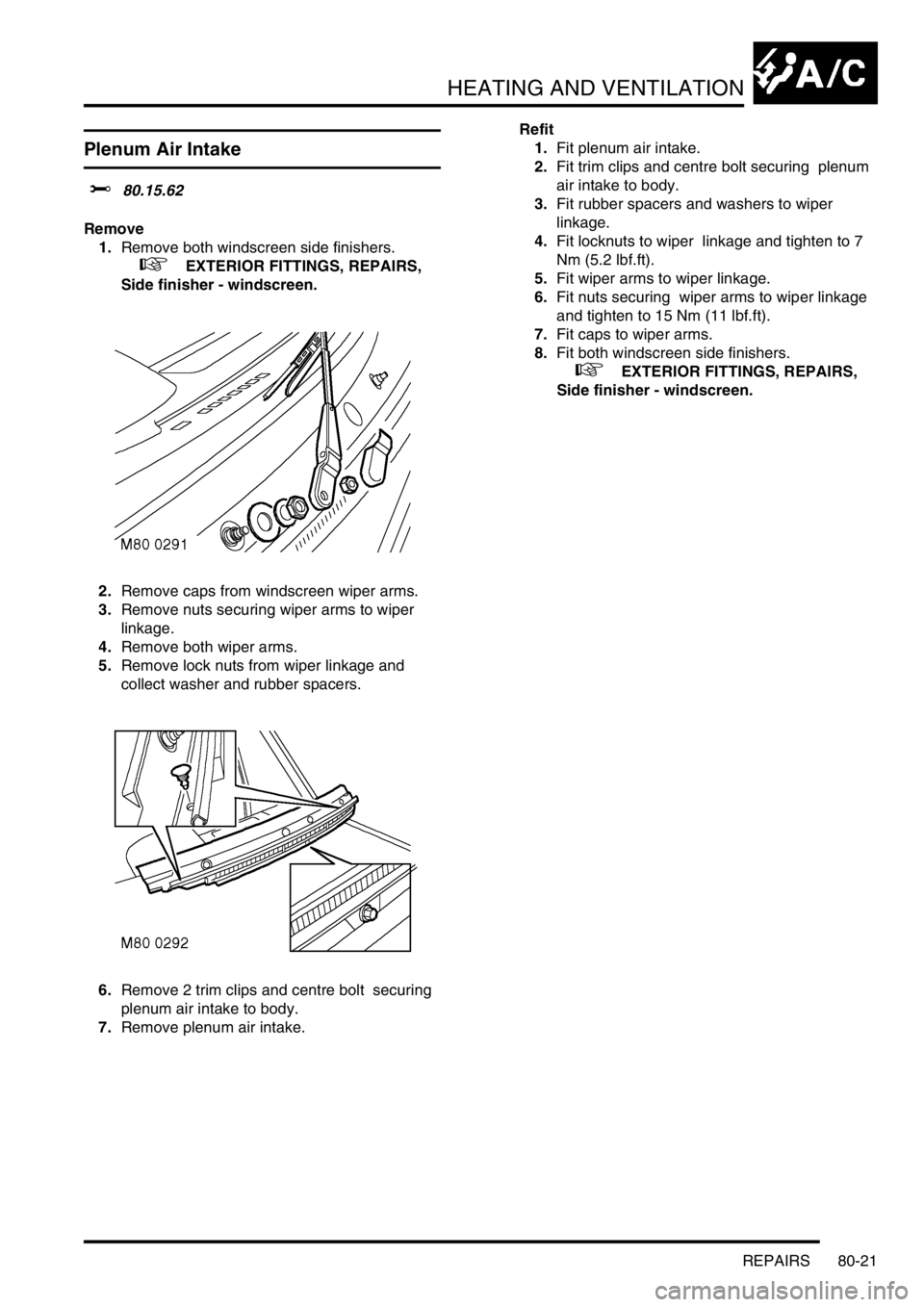
Remove
1.Remove both windscreen side finishers.
+ EXTERIOR FITTINGS, REPAIRS,
Side finisher - windscreen.
2.Remove caps from windscreen wiper arms.
3.Remove nuts securing wiper arms to wiper
linkage.
4.Remove both wiper arms.
5.Remove lock nuts from wiper linkage and
collect washer and rubber spacers.
6.Remove 2 trim clips and centre bolt securing
plenum air intake to body.
7.Remove plenum air intake. Refit
1.Fit plenum air intake.
2.Fit trim clips and centre bolt securing plenum
air intake to body.
3.Fit rubber spacers and washers to wiper
linkage.
4.Fit locknuts to wiper linkage and tighten to 7
Nm (5.2 lbf.ft).
5.Fit wiper arms to wiper linkage.
6.Fit nuts securing wiper arms to wiper linkage
and tighten to 15 Nm (11 lbf.ft).
7.Fit caps to wiper arms.
8.Fit both windscreen side finishers.
+ EXTERIOR FITTINGS, REPAIRS,
Side finisher - windscreen.
Page 1187 of 1529
HEATING AND VENTILATION
80-30REPAIRS
Pipe - Heater - Return
$% 80.25.12
Remove
1.Drain engine coolant.
+ COOLING SYSTEM - V8,
ADJUSTMENTS, Drain and refill.
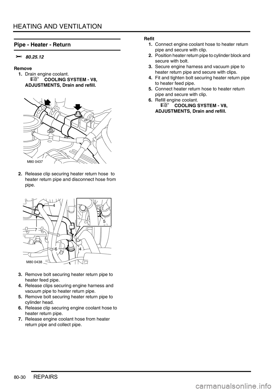
2.Release clip securing heater return hose to
heater return pipe and disconnect hose from
pipe.
3.Remove bolt securing heater return pipe to
heater feed pipe.
4.Release clips securing engine harness and
vacuum pipe to heater return pipe.
5.Remove bolt securing heater return pipe to
cylinder head.
6.Release clip securing engine coolant hose to
heater return pipe.
7.Release engine coolant hose from heater
return pipe and collect pipe.Refit
1.Connect engine coolant hose to heater return
pipe and secure with clip.
2.Position heater return pipe to cylinder block and
secure with bolt.
3.Secure engine harness and vacuum pipe to
heater return pipe and secure with clips.
4.Fit and tighten bolt securing heater return pipe
to heater feed pipe.
5.Connect heater return hose to heater return
pipe and secure with clip.
6.Refill engine coolant.
+ COOLING SYSTEM - V8,
ADJUSTMENTS, Drain and refill.
M80 0437
M80 0438
4
46
7
5
Page 1198 of 1529
AIR CONDITIONING
DESCRIPTION AND OPERATION 82-9
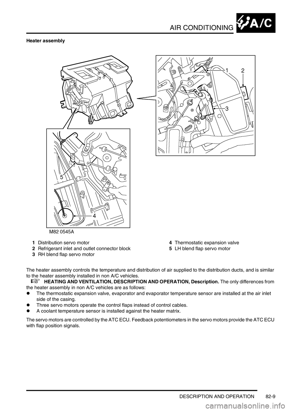
Heater assembly
1Distribution servo motor
2Refrigerant inlet and outlet connector block
3RH blend flap servo motor4Thermostatic expansion valve
5LH blend flap servo motor
The heater assembly controls the temperature and distribution of air supplied to the distribution ducts, and is similar
to the heater assembly installed in non A/C vehicles.
+ HEATING AND VENTILATION, DESCRIPTION AND OPERATION, Description. The only differences from
the heater assembly in non A/C vehicles are as follows:
lThe thermostatic expansion valve, evaporator and evaporator temperature sensor are installed at the air inlet
side of the casing.
lThree servo motors operate the control flaps instead of control cables.
lA coolant temperature sensor is installed against the heater matrix.
The servo motors are controlled by the ATC ECU. Feedback potentiometers in the servo motors provide the ATC ECU
with flap position signals.
Page 1208 of 1529

AIR CONDITIONING
DESCRIPTION AND OPERATION 82-19
Diagnostics
The ATC ECU performs a diagnostic check each time the ignition is switched on. To avoid nuisance fault indications
at low light levels, the sunlight sensor is omitted from the diagnostic check. If a fault is detected, the audible warning
sounds three times and the AUTO window on the control panel display flashes for 20 seconds. The ATC ECU then
reverts to normal control but uses a default value or strategy for the detected fault. Faults are identified by performing
a manual diagnostic check of the system.
A manual diagnostic check includes a check of the sunlight sensor, and is initiated by pressing and holding the AUTO
switch and the air distribution switch, then turning the ignition switch from off to on. The audible warning sounds once
and the indications on the control panel display illuminate. FC is shown in the LH temperature window and the results
of the check are shown as a two digit fault code in the RH temperature window. If a fault is detected, the audible
warning sounds three times and the AUTO window on the display flashes on and off for 20 seconds. If more than one
fault is detected, the fault codes cycle in numerical order, at 1 Hz. The audible warning sounds as each fault code is
shown. In low light conditions, to avoid false sunlight sensor fault indications, the sunlight sensor should be illuminated
with a strong light source.
Diagnostic fault codes and fault descriptions
Code Component Fault Default value/strategy
00 - No fault found -
11 In-car temperature sensor Open or short circuit 25°C (77°F)
12 Ambient temperature sensor Open or short circuit 10°C (50°F)
Cooling fan permanently on
Display shows "- -" if external air
temperature selected
13 Thermistor Open or short circuit 0°C (32°F)
14 Heater coolant temperature sensor Open or short circuit 70°C (158°F)
21 Sunlight sensor, left output Open or short circuit No solar heating correction
22 Sunlight sensor, right output Open or short circuit No solar heating correction
31 LH temperature servo motor Open or short circuit
Motor or flap mechanism seizedServo motor locked in position
32 RH temperature servo motor Open or short circuit
Motor or flap mechanism seizedServo motor locked in position
33 Distribution servo motor Open or short circuit
Motor or flap mechanism seizedServo motor locked in position
Page 1212 of 1529

AIR CONDITIONING
DESCRIPTION AND OPERATION 82-23
Description
The rear air conditioning system cools and recirculates air at the rear of the cabin. The system consists of refrigerant
lines, a rear evaporator/blower assembly, a distribution system and a control panel.
Cooled air from the rear evaporator/blower assembly is supplied by the distribution system to vent outlets above each
second and third row seat. The system is controlled by two switches on the control panel.
Refrigerant lines
Two refrigerant lines connect the rear evaporator/blower assembly to the front A/C refrigerant system. The lines are
routed along the LH underside of the vehicle and secured to a connector block in the floor. A heat shield protects the
lines where they pass above the rear silencer.
Page 1221 of 1529
AIR CONDITIONING
82-32REPAIRS
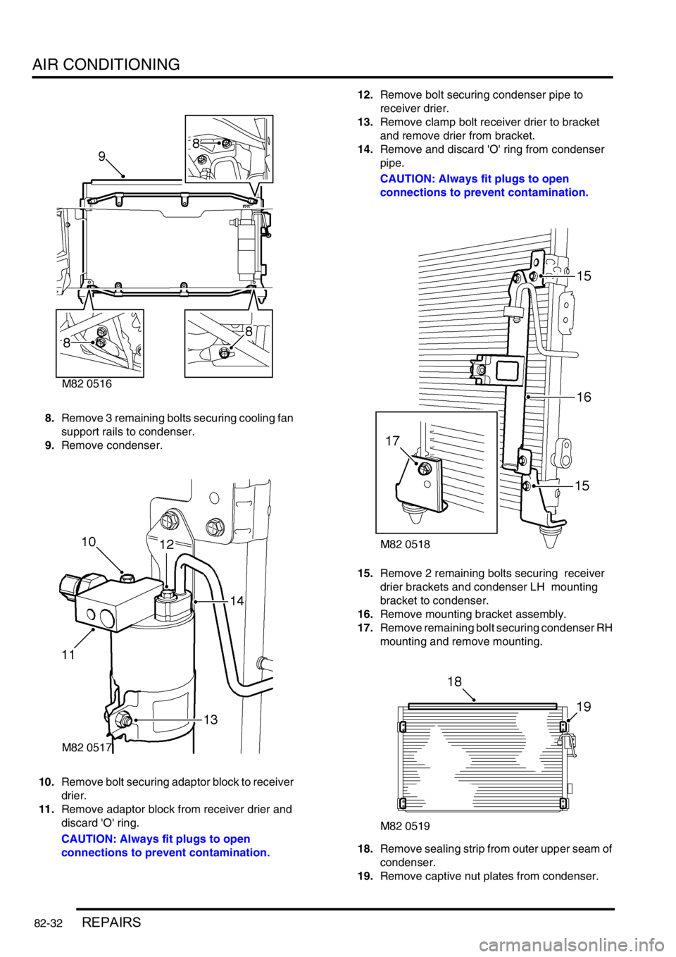
8.Remove 3 remaining bolts securing cooling fan
support rails to condenser.
9.Remove condenser.
10.Remove bolt securing adaptor block to receiver
drier.
11.Remove adaptor block from receiver drier and
discard 'O' ring.
CAUTION: Always fit plugs to open
connections to prevent contamination.12.Remove bolt securing condenser pipe to
receiver drier.
13.Remove clamp bolt receiver drier to bracket
and remove drier from bracket.
14.Remove and discard 'O' ring from condenser
pipe.
CAUTION: Always fit plugs to open
connections to prevent contamination.
15.Remove 2 remaining bolts securing receiver
drier brackets and condenser LH mounting
bracket to condenser.
16.Remove mounting bracket assembly.
17.Remove remaining bolt securing condenser RH
mounting and remove mounting.
18.Remove sealing strip from outer upper seam of
condenser.
19.Remove captive nut plates from condenser.