1999 LAND ROVER DISCOVERY reset
[x] Cancel search: resetPage 1374 of 1529

IN CAR ENTERTAINMENT
DESCRIPTION AND OPERATION 86-6-7
Multi function buttons
Rotary controls are located on the front of the radio cassette for adjustment of bass, treble etc, depending on current
mode selected. Operation of presets 1-6 depends on current mode of operation and allows selection of radio band
(Radio mode on) or CD-autochanger disc (in the CD mode). Scan (Mode dependent) manual or automatic selection
of band or track. RND random play, MODE/MUTE (mode dependent) when pressed the button allows manual
operation or alternate mode selections such as manual tuning, compact disk cue/review, tape forward/rewind modes.
Internal memory
An internal memory chip stores the station presets and security code, power is supplied internally to the chip via a
permanent power feed, supplied from the passenger compartment fuse box.
High line system radio cassette
The high line radio cassette is located in the center of the fascia and contains the radio and tape player. Two clips
(accessible through slots in the front of the unit) secure the unit. To remove the radio cassette unit the two clips must
be released with a special tool. The high line system can be controlled from the fascia mounted radio cassette, or from
remote radio control switches on the left hand side of the steering wheel. In vehicles fitted with radio headphone
amplifiers, the rear seat passengers can control their individual audio output using a headphone amplifier control
panel. The audio signal can be from the radio, cassette player or a CD-autochanger. A logic control circuit in the radio
cassette player controls the operation in the various control modes.
The radio cassette has a display screen, information shown includes current status, station (Radio mode) , CD-
autochanger track/disc status or status of headphone amplifier. Power for illumination on the radio cassette is supplied
from the passenger compartment fusebox. A main fuse is also located in the connector socket area on the back of
the radio cassette. When the radio cassette switch is on, power is made available via internal circuits to the radio
headphone amplifiers.
Security code function
A combination of buttons on the radio cassette are used to input and change security codes. Security codes make the
unit unusable if the unit is disconnected from the vehicle without deactivating the security code. The radio cassette
has an internal memory chip that stores the information, if the power is removed from the unit the chip will activate the
security code feature. For this reason the security code feature must be deactivated before the unit is removed or the
vehicles battery is disconnected.
Audio functions
A rotary knob allows changes of levels or selections during the various modes of operation, this includes volume,
bass, treble, fader and spatial on/off.
Cassette functions
The radio cassette has buttons for the following cassette functions; eject, fast forward, rewind and dolby. The dolby
symbol is shown on the dot matrix display screen if dolby mode is selected.
Radio functions
The radio cassette has buttons for the selection of AM or FM reception. Selection of the radio station is controlled by
the use of the multi-function buttons on the radio cassette player, the radio headphone amplifiers or the remote radio
controls on the steering wheel.
CD-autochanger functions
The CD button on the radio cassette player allows selection of the CD-autochanger. CD disc and track selection is
controlled by the use of the multi-function buttons on the radio cassette player, the radio headphone amplifiers or the
remote radio controls on the steering wheel.
Traffic information function
A traffic/news information button (I) allows traffic or news information to be selected on the FM waveband only, in this
mode the radio will mute when traffic or news messages are received. After the traffic or news message the radio,
cassette tape or CD will resume play, the traffic and news information varies with the country of use and radio band
selected.
Page 1375 of 1529
IN CAR ENTERTAINMENT
86-6-8 DESCRIPTION AND OPERATION
Multi function buttons
The music symbol button is used for mode selection for adjustment of bass, treble etc. depending on current mode
selected. Operation of presets 1-6 depends on current mode of operation and allows selection of radio band (Radio
mode on) or CD-autochanger disc (in the CD mode). Search/Seek (Mode dependent) manual or automatic selection
of band or track. MAN (mode dependent) when pressed the button allows manual operation or alternate mode
selections such as manual tuning, compact disk cue/review, tape forward/rewind modes. The mode dependent SCAN
button allows automatic searching of radio bands, tape or compact disk tracks.
Internal memory
An internal memory chip stores the station presets and security code, power is supplied internally to the chip via a
permanent power feed, supplied from the passenger compartment fuse box.
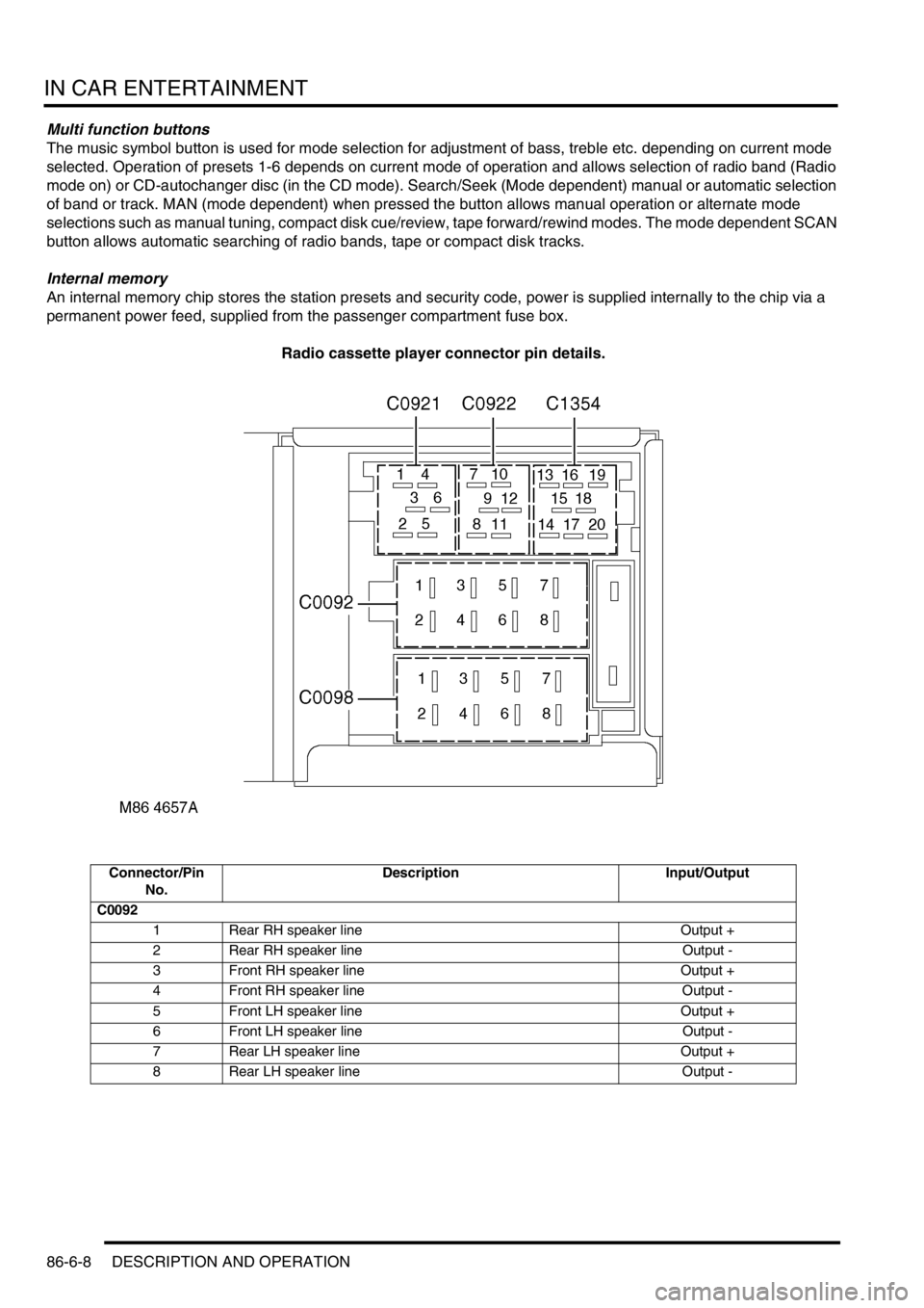
Radio cassette player connector pin details.
Connector/Pin
No.Description Input/Output
C0092
1 Rear RH speaker line Output +
2 Rear RH speaker line Output -
3 Front RH speaker line Output +
4 Front RH speaker line Output -
5 Front LH speaker line Output +
6 Front LH speaker line Output -
7 Rear LH speaker line Output +
8 Rear LH speaker line Output -
Page 1394 of 1529
IN CAR ENTERTAINMENT
DESCRIPTION AND OPERATION 86-6-27
Operation
DVD Player Functionality
The following defines the functionality of the unit. Further details of system operation can found in the DVD System
Owner's Manual, Publication Part No. LRL0482, supplied with the system.
DVD Region Selection
The DVD player is capable of playing discs from any region. The DVD can only be set to play discs of one region at
a time. A code is entered using the remote control handset to set the unit to the required region. The unit is set to the
correct region on production and therefore this will not be required by either the dealer or the customer.
If the unit region is required to be changed for any reason, Land Rover Special Vehicles must be contacted for the
required code and procedure.
NOTE: The unit can be re-configured for region up to five times. After the fifth attempt to re-configure the region, the
unit will be locked in the fifth region that was programmed. This will require the unit to be returned to the manufacturer
to be reset. The manufacturer will charge a fee for this service.
DVD Player CD Audio Function
The DVD player can play audio CD's through the vehicle audio system. This allows the user to play additional CD's
without having to remove the CD autochanger cartridge.
The overhead console LCD monitor must be open to play audio CD's.. Normal audio CD functionality such as repeat,
random and track select etc. can be accessed using the remote control handset.
The DVD player in the overhead console will also function independently of the vehicle audio system, and operate as
an additional CD player. The rear seat passengers can listen to audio CD's via the three headphone sockets on the
overhead console and via the two radio/headphone amplifier units (if fitted), while the front seat passengers
simultaneously listen to CD's played on the vehicle audio system and CD autochanger.
DVD/CD Output using the Vehicle Audio System
To play the DVD/CD audio output from the overhead console through the vehicle audio speakers, the speaker button
on the overhead console or remote control handset must be pressed. 'Speaker On' appears on the LCD monitor and
the head unit CD functionality is suspended. The audio output from the overhead console will now be played from the
vehicle speaker system. The head unit volume control, tone control, Navigation announcements and mobile phone (if
fitted) will function as normal and override the DVD output. A second press of the speaker button will switch the audio
output back to the head unit. 'Speaker Off' will be displayed on the LCD monitor.
The overhead console will remember the selected speaker condition if the overhead console is switched off by closing
the monitor, the console switched off using the handset or accessory power removed from the overhead console.
Power Up Conditions
On application of accessory power, the overhead console will perform the following:
lIf no disc is in the DVD player, the LCD monitor will display a blue screen and enter 'AUX' input mode.
When a DVD or CD is inserted in the DVD player, the system will change to DVD input mode. The disc will
attempt to play but may be limited by the disc media. Some discs will play automatically, some will display a menu
and others require the user to start playback.
lIf a disc was in the DVD player and the system was in 'Play', 'Pause', 'FF' or 'Rew' when powered down, playback
will start when power is re-applied.
lIf a disc was in the DVD player and the system was in 'Stop' when powered down, the system will enter DVD
mode and a blue screen will be displayed on the LCD monitor.
lSpeaker selection will remain in the same state as when the accessory power was removed.
Engine Cranking
If the unit is playing a DVD or CD when the ignition switch is moved to position III (engine crank), the system will stop
playing while the engine is cranking. Playback will resume at the point the playback was stopped when the ignition
switch is returned to position I or II.
Page 1459 of 1529
NAVIGATION SYSTEM
87-6 DESCRIPTION AND OPERATION
Service Menu
The service menu provides access to details of the navigation computer hardware and software, and can be accessed
when the navigation computer is in radio mode, by simultaneously pressing the NAV button and the 10 multifunction
buttons. The following items can then be scrolled through by pressing the Nxt (next) and Prv (previous) multifunction
buttons, or turning the RH rotary control:
lModel No.
lSerial No.
lChanger Reset
lGAL
lRadio Software
lRadio Bolo
lNavi Rom
lNavi Flash
lRTC Value
When Changer Reset is displayed, the CD autochanger (where fitted) can be reset by pressing the appropriate
multifunction button.
When the End multifunction button is pressed, the navigation computer quits the service menu and returns to radio
mode.
Garage Menu
Garage menu enables the navigation system to be tested and calibrated, and also contains a route navigation
demonstration. The garage menu is entered from the main navigation menu, as follows:
1Press the Nav button to access the system settings.
2Press and hold multifunction button 3, then press multifunction button 5 to display the garage menu.
The garage menu contains the following, which can be accessed using the RH rotary control:
lCALIBRATION RIDE – Used to calibrate the navigation computer, to enable route navigation.
lGPS INFO– Provides functional test of antenna by checking GPS reception. If functioning correctly, displays the
number of satellites being received, the date, time (Greenwich Mean Time) and the type of positional fix currently
possible.
lCALIBRATION– Allows vehicle specific calibration data to be entered, e.g. tyre size. Also allows current
calibration to be deleted prior to re-calibrating.
NOTE: Only known calibration data should be entered. The navigation computer cannot make route
calculations if incorrect data is entered.
lSENSORS– Allows wheel speed, reverse gear and gyro sensor inputs to be checked.
lVERSION– Displays navigation computer hardware and software details.
lSPEECH TEST– Performs a test of the navigation computer audio output.
lMODULE TEST– Performs a test routine on the internal components of the navigation computer.
lDEMO – Allows a route navigation demonstration to be run.
To quit the garage menu, press the Nav button.
Page 1462 of 1529
NAVIGATION SYSTEM
DESCRIPTION AND OPERATION 87-9
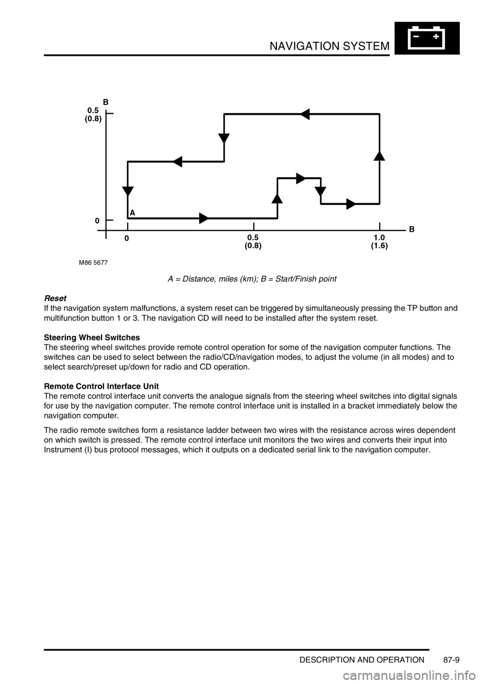
A = Distance, miles (km); B = Start/Finish point
Reset
If the navigation system malfunctions, a system reset can be triggered by simultaneously pressing the TP button and
multifunction button 1 or 3. The navigation CD will need to be installed after the system reset.
Steering Wheel Switches
The steering wheel switches provide remote control operation for some of the navigation computer functions. The
switches can be used to select between the radio/CD/navigation modes, to adjust the volume (in all modes) and to
select search/preset up/down for radio and CD operation.
Remote Control Interface Unit
The remote control interface unit converts the analogue signals from the steering wheel switches into digital signals
for use by the navigation computer. The remote control interface unit is installed in a bracket immediately below the
navigation computer.
The radio remote switches form a resistance ladder between two wires with the resistance across wires dependent
on which switch is pressed. The remote control interface unit monitors the two wires and converts their input into
Instrument (I) bus protocol messages, which it outputs on a dedicated serial link to the navigation computer.
Page 1468 of 1529
NAVIGATION SYSTEM
DESCRIPTION AND OPERATION 87-15
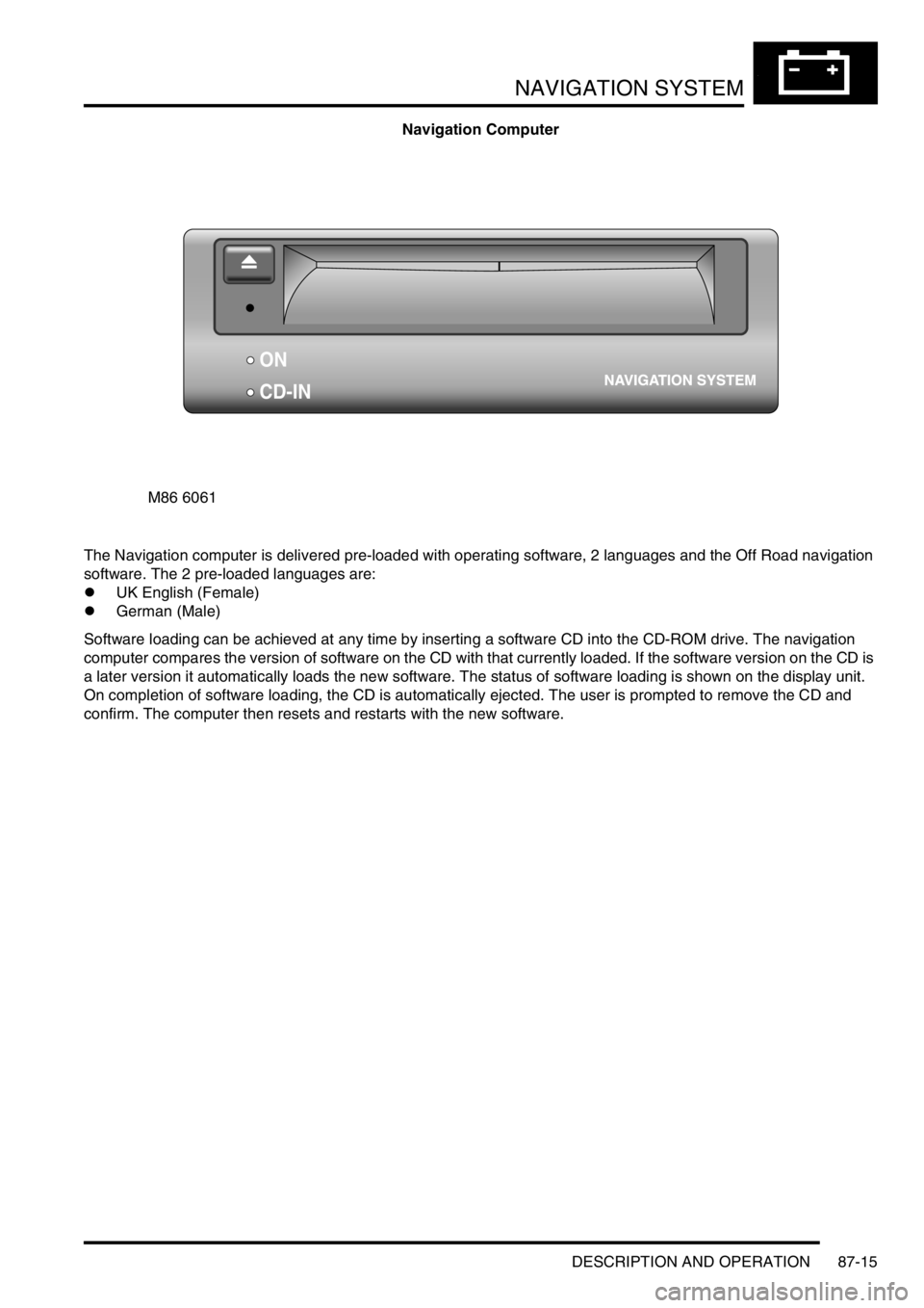
Navigation Computer
The Navigation computer is delivered pre-loaded with operating software, 2 languages and the Off Road navigation
software. The 2 pre-loaded languages are:
lUK English (Female)
lGerman (Male)
Software loading can be achieved at any time by inserting a software CD into the CD-ROM drive. The navigation
computer compares the version of software on the CD with that currently loaded. If the software version on the CD is
a later version it automatically loads the new software. The status of software loading is shown on the display unit.
On completion of software loading, the CD is automatically ejected. The user is prompted to remove the CD and
confirm. The computer then resets and restarts with the new software.
M86 6061
ON
CD-IN
Page 1488 of 1529
INSTRUMENTS
DESCRIPTION AND OPERATION 88-5
Description
General
The instrument pack consists of four analogue dials, four warning lamp packs and a Liquid Crystal Display (LCD)
odometer.
The four dials are used to indicate:
lRoad speed.
lEngine speed.
lFuel tank level.
lEngine coolant temperature.
The dials are driven by a microprocessor from information received from the serial communication link. Information
input is received as either:
lDigital.
lAnalogue.
lPulse train.
lPulse Width Modulation (PWM).
The LCD provides information for:
lOdometer.
lTrip distance.
lSelected gear (on vehicles fitted with an automatic gearbox).
A trip reset button is provided to zero the trip display, this button also allows the selection of "miles" or "kilometres"
for the display. A photocell controls the illumination of the LCD, maintaining contrast of the display during ambient light
changes.
Within the four warning lamp packs there are 28 lamps. A long life bulb illuminates the high beam warning lamp and
the rest of the warning lamps are illuminated by Light Emitting Diodes (LED's). All warning lamp legends are invisible
until lit. When lit the symbols are illuminated on a black background.
The warning lamps illuminate in one of four colours. The colour indicates the level of importance to the driver, as
follows:
lRed = warning.
lAmber = caution.
lGreen = system operative.
lBlue = main beam operative.
The first warning lamp pack is located in the top left-hand side of the instrument pack and contains the following
warning lamps:
lTraction control warning lamp.
lTransfer box in neutral warning lamp.
lDifferential lock warning lamp
lOverspeed warning lamp (activated for gulf market only).
lBrake system warning lamp.
lHill Descent Control (HDC) information warning lamp.
lMalfunction Indicator Lamp (MIL)/ SERVICE ENGINE SOON warning lamp.
The second warning lamp pack is located in the centre of the instrument pack and contains the following warning
lamps:
lDirection indicator warning lamps.
lHigh beam warning lamp.
lAnti-lock brake system warning lamp.
Page 1490 of 1529
INSTRUMENTS
DESCRIPTION AND OPERATION 88-7
LCD odometer/trip meter
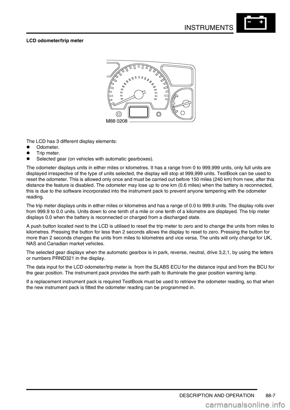
The LCD has 3 different display elements:
lOdometer.
lTrip meter.
lSelected gear (on vehicles with automatic gearboxes).
The odometer displays units in either miles or kilometres. It has a range from 0 to 999,999 units, only full units are
displayed irrespective of the type of units selected, the display will stop at 999,999 units. TestBook can be used to
reset the odometer. This is allowed only once and must be carried out before 150 miles (240 km) from new, after this
distance the feature is disabled. The odometer may lose up to one km (0.6 miles) when the battery is reconnected,
this is due to the software incorporated into the instrument pack to prevent anyone tampering with the odometer
reading.
The trip meter displays units in either miles or kilometres and has a range of 0.0 to 999.9 units. The display rolls over
from 999.9 to 0.0 units. Units down to one tenth of a mile or one tenth of a kilometre are displayed. The trip meter
displays 0.0 when the battery is reconnected or charged from a discharged state.
A push button located next to the LCD is utilised to reset the trip meter to zero and to change the units from miles to
kilometres. Pressing the button for less than 2 seconds allows the display to reset to zero. Pressing the button for
more than 2 seconds changes the units from miles to kilometres and vice versa. The units will only change for UK,
NAS and Canadian market vehicles.
The selected gear displays when the automatic gearbox is in park, reverse, neutral, drive 3,2,1, by using the letters
or numbers PRND321 in the display.
The data input for the LCD odometer/trip meter is from the SLABS ECU for the distance input and from the BCU for
the gear position. The instrument pack provides the earth path to illuminate the gear position warning lamp.
If a replacement instrument pack is required TestBook must be used to retrieve the odometer reading, so that when
the new instrument pack is fitted the odometer reading can be programmed in.