Page 1433 of 1529

HARNESSES
86-7-28 REPAIRS
50.Feed harness through to front panel.
51.Secure fog lamp multiplug.
52.Connect headlamp level motor, headlamp and
side lamp multiplugs.
53.Fit indicator lamp.
+ LIGHTING, REPAIRS, Lamp - front
repeater - up to 03MY.
54.Secure harness to RH front panel.
55.Connect cooling fan and horn multiplug.
56.Secure harness to lower support rail.
57.Connect receiver drier and air temperature
sensor multiplugs.
58.Fit front bumper.
+ EXTERIOR FITTINGS, REPAIRS,
Bumper assembly - front.
59.Fit battery tray.
60.Fit air filter assembly.
+ ENGINE MANAGEMENT SYSTEM -
V8, REPAIRS, Air cleaner assembly.
61.Position both lower 'A' post trims and secure
with studs.
62.Fit heater assembly.
+ HEATING AND VENTILATION,
REPAIRS, Heater assembly - models with
air conditioning.
+ HEATING AND VENTILATION,
REPAIRS, Heater assembly - models
without air conditioning.
Harness - main - DVD unit
$% 86.70.25
Remove
1.Remove battery cover and disconnect the
battery earth lead.
2.Remove CD switch box.
+ IN CAR ENTERTAINMENT,
REPAIRS, Switch box - CD/DVD player.
3.Remove DVD player unit.
+ IN CAR ENTERTAINMENT,
REPAIRS, DVD screen/player unit.
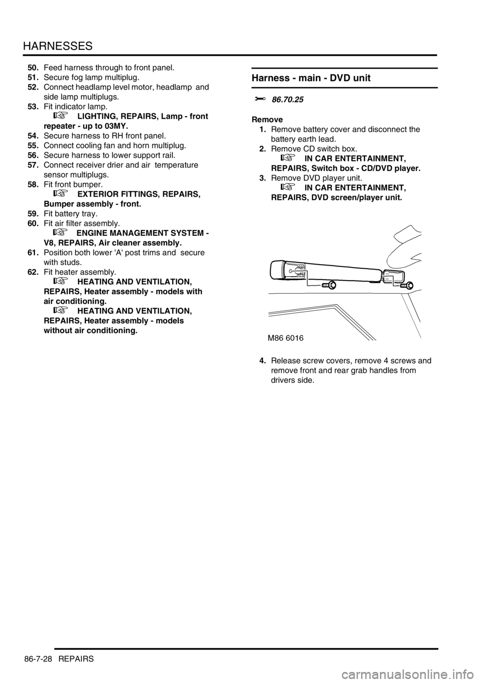
4.Release screw covers, remove 4 screws and
remove front and rear grab handles from
drivers side.
Page 1438 of 1529
DRIVING AIDS
DESCRIPTION AND OPERATION 86-8-1
DRIV ING AIDS DESCRIPTION AND OPERAT ION
Park Distance Control – Component
Location
1Park Distance Control (PDC) Switch
2PDC ECU
3PDC sounder4Mounting bracket
5PDC sensor
Page 1440 of 1529
DRIVING AIDS
DESCRIPTION AND OPERATION 86-8-3
1PDC sounder
2PDC switch
3Fusible link
4Ignition switch
5Fuse
6PDC ECU
7PDC sensors
Page 1441 of 1529
DRIVING AIDS
86-8-4 DESCRIPTION AND OPERATION
Description
General
Park Distance Control (PDC) is introduced on vehicles from 03 model year. PDC provides an audible warning to the
driver when any obstacles are in the path of the vehicle during a reversing manoeuvre. The purpose of the system is
to assist the driver when parking and is not designed as a crash avoidance system or a replacement for visual
interpretation by the driver.
The system comprises four ultrasonic sensors in the rear bumper, an ECU, a fascia mounted momentary switch and
a sounder unit. The system operates using ultrasonic signals which are transmitted by the sensors. The reflected echo
from this output is received by the sensors and used by the PDC ECU to calculate the distance from an object.
The fascia mounted switch allows the driver to de-activate the PDC system if operation is not required or the vehicle
has a trailer attached.
Page 1443 of 1529
DRIVING AIDS
86-8-6 DESCRIPTION AND OPERATION
PDC ECU Connector Pin Details
aConnector C0958
bConnector C0957
Connector C0958
Connector C0957
Pin No. Description Input/Output
1 Ignition switch power supply Input
2 Sounder - Negative Input
3 Not used–
4PDC Switch Input
5 Not used–
6 Reverse Gear signal Input
7 Not used–
8Ground–
9 Not used–
10 Sounder - Positive 12V supply Output
11 Not used–
12 Not used–
13 PDC Switch LED Output
14 to 16 Not used–
Pin No. Description Input/Output
1 Not used–
2 Sensor - RH Inner - Signal Input
3 Sensor - Rear LH Inner - Signal Input
4 Sensor - Rear RH Outer - Signal Input
5 Sensor - Rear LH Outer - Signal Input
6 and 7 Not used–
8 Ground - All sensors Input
9 Not used–
10 Power Supply - All sensors Output
11 and 12 Not used–
Page 1444 of 1529

DRIVING AIDS
DESCRIPTION AND OPERATION 86-8-7
Inputs and Outputs
Two connectors provide the interface between the PDC ECU and the external PDC components.
The ECU receives inputs from the following:
lReverse lamp circuit – for system activation when reverse gear is selected
lPDC switch – for activation and de-activation of the system
lIgnition switch – power supply for system operation.
The ECU outputs to the following:
lSensors – power and ground connections
lSensor – digital signal transmit and receive signals
lSounder – signal for sounder operation
lPDC Switch – power supply for switch LED operation.
Diagnostics
The PDC ECU has no diagnostic connection to enable faults to be retrieved using TestBook/T4. An on-board
diagnostic routine monitors the system and alerts the driver to a system fault by emitting a tone from the sounder.
If a PDC system fault has occurred, the sounder will emit a continuous tone for 3 seconds and the PDC switch LED
will flash continuously when reverse gear is selected.
Page 1445 of 1529

DRIVING AIDS
86-8-8 DESCRIPTION AND OPERATION
Sensors
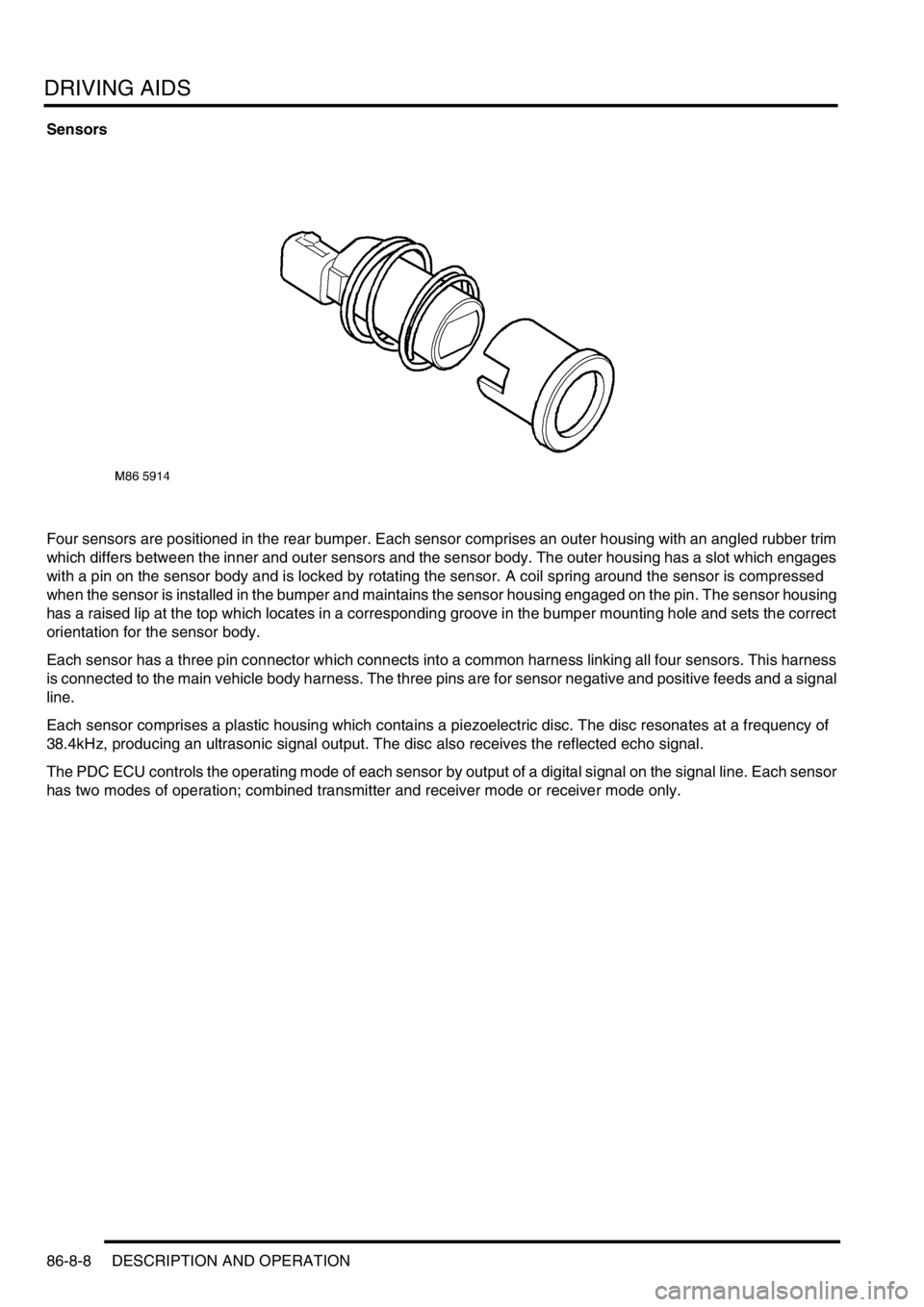
Four sensors are positioned in the rear bumper. Each sensor comprises an outer housing with an angled rubber trim
which differs between the inner and outer sensors and the sensor body. The outer housing has a slot which engages
with a pin on the sensor body and is locked by rotating the sensor. A coil spring around the sensor is compressed
when the sensor is installed in the bumper and maintains the sensor housing engaged on the pin. The sensor housing
has a raised lip at the top which locates in a corresponding groove in the bumper mounting hole and sets the correct
orientation for the sensor body.
Each sensor has a three pin connector which connects into a common harness linking all four sensors. This harness
is connected to the main vehicle body harness. The three pins are for sensor negative and positive feeds and a signal
line.
Each sensor comprises a plastic housing which contains a piezoelectric disc. The disc resonates at a frequency of
38.4kHz, producing an ultrasonic signal output. The disc also receives the reflected echo signal.
The PDC ECU controls the operating mode of each sensor by output of a digital signal on the signal line. Each sensor
has two modes of operation; combined transmitter and receiver mode or receiver mode only.
Page 1448 of 1529

DRIVING AIDS
DESCRIPTION AND OPERATION 86-8-11
Operation
PDC System Operation
When the ignition switch is in position II and reverse gear is selected, the PDC sensors are automatically activated.
The PDC ECU only activates the system if reverse is selected for more than 1 second. This avoids nuisance audible
warnings when the gear selector lever is being moved between Drive and Park on vehicles with automatic
transmission.
When the system is activated, the PDC ECU illuminates the indicator LED in the PDC switch, switches on the
ultrasonic sensors and generates a single chime on the PDC sounder to indicate the system is active. If an object is
range of the sensors when the system is activated, a series of audible warnings are emitted by the PDC sounder
immediately.
If PDC operation is not required, it can be suspended temporarily by pressing the PDC switch. When reverse is
deselected and subsequently reselected, PDC will automatically become active again.
PDC can also be manually selected when not in reverse gear by pressing the PDC switch. A second press of the
switch is required to turn off the PDC or the PDC will be deactivated if reverse is selected and then deselected.
Sensor Operation
The PDC ECU processes the distance readings from the ultrasonic sensors to determine if there are any objects
within the detection areas. If there are no objects in the detection areas, there are no further audible warnings. If an
object is detected, repeated audible warnings are produced on the PDC sounder.
The maximum detection range is 1800 mm (70 in). When an object is detected, the time delay between the audible
warning tones decreases as the distance between the detected object and the vehicle decreases until, at
approximately 450 mm (17 in), the audible warning tone is continuous.
After the initial detection of an object, if there is no decrease in the distance between an object and the central sensors,
the time delay between the audible warnings remains constant. If an object is detected by one of the corner sensors
only, the audible warnings stop after about 5 seconds if there is no change in the distance between the object and the
corner sensor.