1999 LAND ROVER DISCOVERY sensor
[x] Cancel search: sensorPage 1467 of 1529

NAVIGATION SYSTEM
87-14 DESCRIPTION AND OPERATION
Description
General
Where fitted, the CARiN III and Trafficmaster system combines a satellite navigation system (CARiN III) with a real-
time traffic information system (Trafficmaster).
The satellite navigation system provides computer generated audible and visual route guidance information to enable
the driver to reach a desired destination. The system allows the driver to choose between road navigation and off-
road navigation, and to incorporate waypoints. Road navigation also allows the driver to choose between using minor
or major roads and the quickest or shortest route. Directions to hospitals, museums, monuments, hotels etc. are also
available. The computer uses map information stored on a CD-ROM to determine the best route for the journey and
provide the driver with details of directions and approaching junctions. The current position of the vehicle is
determined using a combination of vehicle sensor inputs and the Global Positioning System (GPS).
The Trafficmaster system displays live traffic flow information on the road navigation map screens. Traffic speed is
indicated on the maps by colour coded roads and arrows. The traffic flow information is relayed from a network of
sensors covering motorways and trunk roads. Data from the sensors is updated on a three minute cycle, 24 hours a
day, 365 days a year.
The navigation system consists of the following components:
lNavigation computer
lGPS antenna
lDisplay unit
lSwitch pack
lNavigation speaker
lTrafficmaster monitor ECU
lTrafficmaster antenna
Navigation Computer
The navigation computer is located in a bracket under the RH front seat, immediately behind the CD autochanger.
The navigation computer contains all the hardware and software required for control of the navigation system,
including the GPS receiver and a solid state piezo gyro. Using the gyro, and inputs from the GPS antenna and the
vehicle K bus, the navigation computer determines the vehicle’s current position, direction and speed.
The navigation computer also houses a CD-ROM drive. The drive is used to read map data from country specific CD’s
and also to load software into the computer. A button, adjacent to the CD slot, is provided to eject the CD from the
unit. If the ignition is on, one press of the button will eject the CD. If the ignition is off, two presses are required, one
to wake up the system and the second to eject the CD. Access to the CD-ROM drive is from the rear of the RH front
seat.
Page 1469 of 1529
NAVIGATION SYSTEM
87-16 DESCRIPTION AND OPERATION
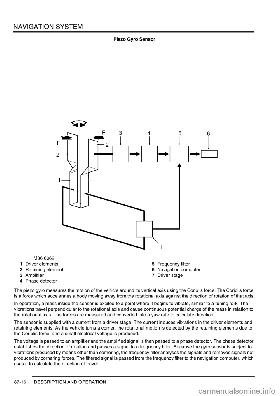
Piezo Gyro Sensor
1Driver elements
2Retaining element
3Amplifier
4Phase detector5Frequency filter
6Navigation computer
7Driver stage
The piezo gyro measures the motion of the vehicle around its vertical axis using the Coriolis force. The Coriolis force
is a force which accelerates a body moving away from the rotational axis against the direction of rotation of that axis.
In operation, a mass inside the sensor is excited to a point where it begins to vibrate, similar to a tuning fork. The
vibrations travel perpendicular to the rotational axis and cause continuous potential charge of the mass in relation to
the rotational axis. The forces are measured and converted into a yaw rate to calculate direction.
The sensor is supplied with a current from a driver stage. The current induces vibrations in the driver elements and
retaining elements. As the vehicle turns a corner, the rotational motion is detected by the retaining elements due to
the Coriolis force, and a small electrical voltage is produced.
The voltage is passed to an amplifier and the amplified signal is then passed to a phase detector. The phase detector
establishes the direction of rotation and passes a signal to a frequency filter. Because the gyro sensor is subject to
vibrations produced by means other than cornering, the frequency filter analyses the signals and removes signals not
produced by cornering forces. The filtered signal is passed from the frequency filter to the navigation computer, which
uses it to calculate the direction of travel.
Page 1472 of 1529

NAVIGATION SYSTEM
DESCRIPTION AND OPERATION 87-19
Trafficmaster Monitor ECU
The Trafficmaster monitor ECU is installed underneath the CD autochanger, below the RH front seat. The
Trafficmaster monitor ECU processes the traffic flow data from the Trafficmaster antenna and combines it with data
from the navigation computer to display on the display unit.
Trafficmaster Antenna
The Trafficmaster antenna is installed in the fascia, on the rear of the instrument pack. The antenna receives radio
signals containing the data relayed from the traffic flow sensors, and transmits the information on a hardwired
connection to the Trafficmaster monitor ECU.
Page 1474 of 1529
NAVIGATION SYSTEM
DESCRIPTION AND OPERATION 87-21
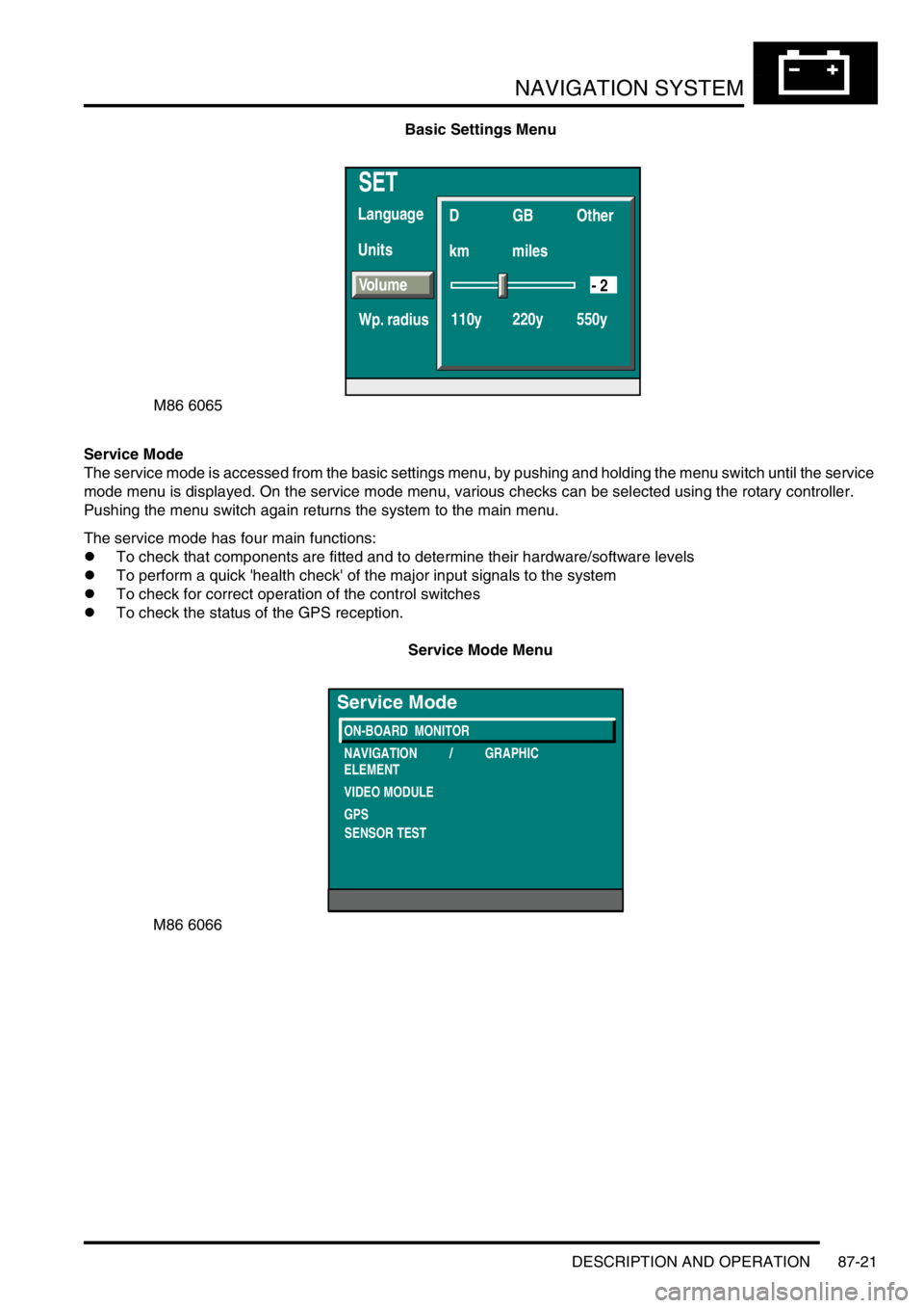
Basic Settings Menu
Service Mode
The service mode is accessed from the basic settings menu, by pushing and holding the menu switch until the service
mode menu is displayed. On the service mode menu, various checks can be selected using the rotary controller.
Pushing the menu switch again returns the system to the main menu.
The service mode has four main functions:
lTo check that components are fitted and to determine their hardware/software levels
lTo perform a quick 'health check' of the major input signals to the system
lTo check for correct operation of the control switches
lTo check the status of the GPS reception.
Service Mode Menu
SET
Units Language
D
km
110y 220y 550ymilesGB Other
Volume
Wp. radius
- 2
M86 6065
M86 6066
ON-BOARD MONITOR
NAVIGATION / GRAPHIC
ELEMENT
VIDEO MODULE
GPS
Service Mode
SENSOR TEST
Page 1475 of 1529
NAVIGATION SYSTEM
87-22 DESCRIPTION AND OPERATION
On-Board Monitor (Display Unit)
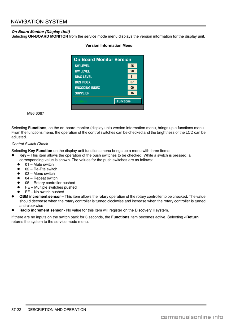
Selecting ON-BOARD MONITOR from the service mode menu displays the version information for the display unit.
Version Information Menu
Selecting Functions, on the on-board monitor (display unit) version information menu, brings up a functions menu.
From the functions menu, the operation of the control switches can be checked and the brightness of the LCD can be
adjusted.
Control Switch Check
Selecting Key Function on the display unit functions menu brings up a menu with three items:
lKey – This item allows the operation of the push switches to be checked. While a switch is pressed, a
corresponding value is shown. The values for the push switches are as follows:
l01 – Mute switch
l02 – Re-Rte switch
l03 – Menu switch
l04 – Repeat switch
l05 – Rotary controller pushed
lFE – Multiple switches pushed
lFF – No switch pushed
lOBM increment sensor – This item allows the rotary operation of the rotary controller to be checked. The value
should decrease when the rotary controller is turned clockwise and increase when the rotary controller is turned
anti-clockwise
lRadio increment sensor - No value for this item will register on the Discovery II system.
If there are no inputs on the switch pack for 3 seconds, the Functions item becomes active. Selecting
M86 6067
On Board Monitor Version
SW LEVEL
HW LEVEL
DIAG LEVEL
BUS INDEX
ENCODING INDEX
SUPPLIER
< Return25
20
11
07
00
16
Functions
Page 1476 of 1529
NAVIGATION SYSTEM
DESCRIPTION AND OPERATION 87-23
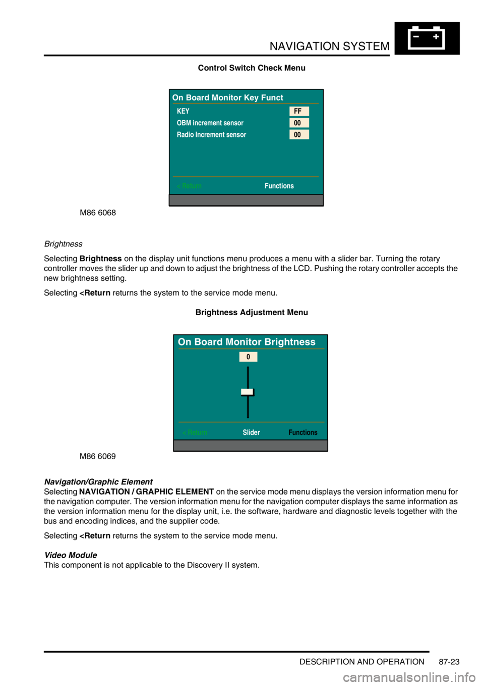
Control Switch Check Menu
Brightness
Selecting Brightness on the display unit functions menu produces a menu with a slider bar. Turning the rotary
controller moves the slider up and down to adjust the brightness of the LCD. Pushing the rotary controller accepts the
new brightness setting.
Selecting
Navigation/Graphic Element
Selecting NAVIGATION / GRAPHIC ELEMENT on the service mode menu displays the version information menu for
the navigation computer. The version information menu for the navigation computer displays the same information as
the version information menu for the display unit, i.e. the software, hardware and diagnostic levels together with the
bus and encoding indices, and the supplier code.
Selecting
This component is not applicable to the Discovery II system.
M86 6068
On Board Monitor Key Funct
KEY
OBM increment sensor
Radio Increment sensor
< ReturnFF
00
00
Functions
M86 6069
On Board Monitor Brightness
< Return SliderFunctions
0
Page 1479 of 1529
NAVIGATION SYSTEM
87-26 DESCRIPTION AND OPERATION
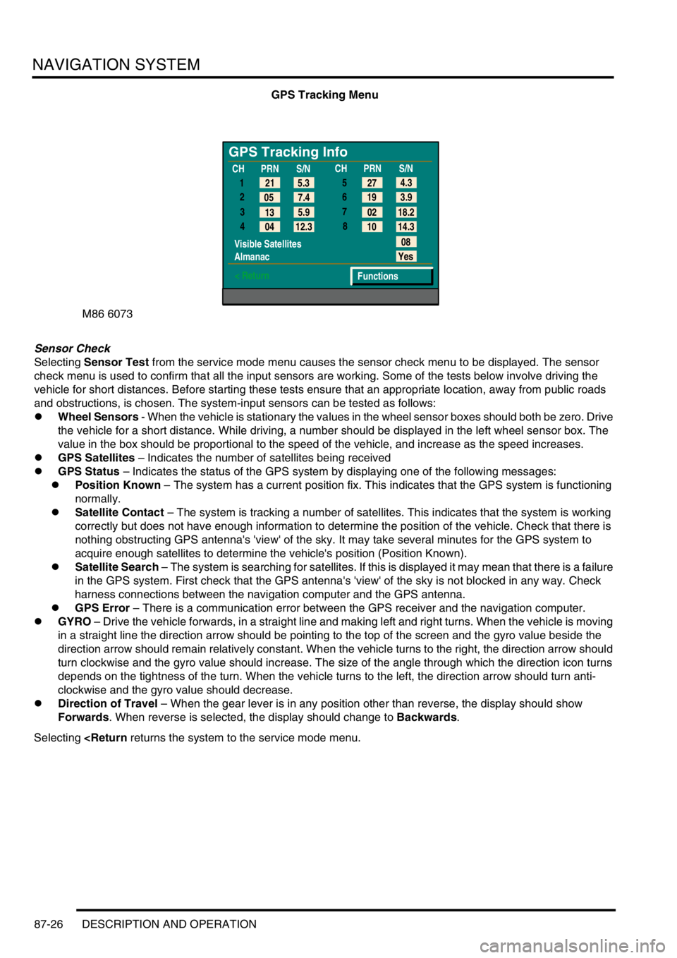
GPS Tracking Menu
Sensor Check
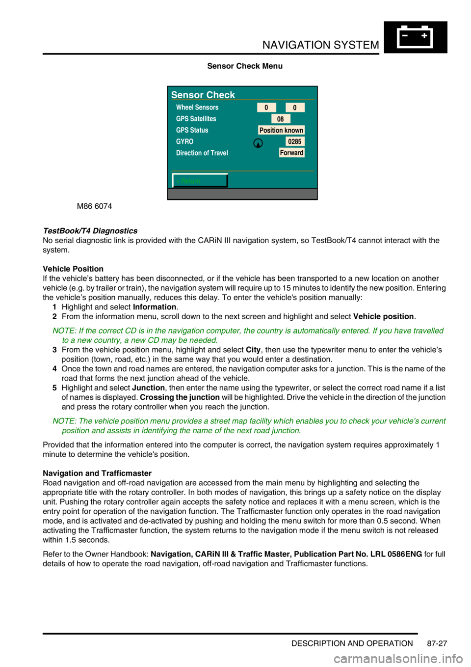
Selecting Sensor Test from the service mode menu causes the sensor check menu to be displayed. The sensor
check menu is used to confirm that all the input sensors are working. Some of the tests below involve driving the
vehicle for short distances. Before starting these tests ensure that an appropriate location, away from public roads
and obstructions, is chosen. The system-input sensors can be tested as follows:
lWheel Sensors - When the vehicle is stationary the values in the wheel sensor boxes should both be zero. Drive
the vehicle for a short distance. While driving, a number should be displayed in the left wheel sensor box. The
value in the box should be proportional to the speed of the vehicle, and increase as the speed increases.
lGPS Satellites – Indicates the number of satellites being received
lGPS Status – Indicates the status of the GPS system by displaying one of the following messages:
lPosition Known – The system has a current position fix. This indicates that the GPS system is functioning
normally.
lSatellite Contact – The system is tracking a number of satellites. This indicates that the system is working
correctly but does not have enough information to determine the position of the vehicle. Check that there is
nothing obstructing GPS antenna's 'view' of the sky. It may take several minutes for the GPS system to
acquire enough satellites to determine the vehicle's position (Position Known).
lSatellite Search – The system is searching for satellites. If this is displayed it may mean that there is a failure
in the GPS system. First check that the GPS antenna's 'view' of the sky is not blocked in any way. Check
harness connections between the navigation computer and the GPS antenna.
lGPS Error – There is a communication error between the GPS receiver and the navigation computer.
lGYRO – Drive the vehicle forwards, in a straight line and making left and right turns. When the vehicle is moving
in a straight line the direction arrow should be pointing to the top of the screen and the gyro value beside the
direction arrow should remain relatively constant. When the vehicle turns to the right, the direction arrow should
turn clockwise and the gyro value should increase. The size of the angle through which the direction icon turns
depends on the tightness of the turn. When the vehicle turns to the left, the direction arrow should turn anti-
clockwise and the gyro value should decrease.
lDirection of Travel – When the gear lever is in any position other than reverse, the display should show
Forwards. When reverse is selected, the display should change to Backwards.
Selecting
GPS Tracking Info
1
2
3
4
Visible Satellites
Almanac
< Return
08
Yes
Functions 5.3 21
7.4 05
5.9
13
12.3
04CHPRN
S/N
CHPRN
S/N
4.3
27
3.9 19
18.2 02
14.3 10 5
6
7
8
Page 1480 of 1529
NAVIGATION SYSTEM
DESCRIPTION AND OPERATION 87-27
Sensor Check Menu
TestBook/T4 Diagnostics
No serial diagnostic link is provided with the CARiN III navigation system, so TestBook/T4 cannot interact with the
system.
Vehicle Position
If the vehicle’s battery has been disconnected, or if the vehicle has been transported to a new location on another
vehicle (e.g. by trailer or train), the navigation system will require up to 15 minutes to identify the new position. Entering
the vehicle’s position manually, reduces this delay. To enter the vehicle's position manually:
1Highlight and select Information.
2From the information menu, scroll down to the next screen and highlight and select Vehicle position.
NOTE: If the correct CD is in the navigation computer, the country is automatically entered. If you have travelled
to a new country, a new CD may be needed.
3From the vehicle position menu, highlight and select City, then use the typewriter menu to enter the vehicle’s
position (town, road, etc.) in the same way that you would enter a destination.
4Once the town and road names are entered, the navigation computer asks for a junction. This is the name of the
road that forms the next junction ahead of the vehicle.
5Highlight and select Junction, then enter the name using the typewriter, or select the correct road name if a list
of names is displayed. Crossing the junction will be highlighted. Drive the vehicle in the direction of the junction
and press the rotary controller when you reach the junction.
NOTE: The vehicle position menu provides a street map facility which enables you to check your vehicle’s current
position and assists in identifying the name of the next road junction.
Provided that the information entered into the computer is correct, the navigation system requires approximately 1
minute to determine the vehicle's position.
Navigation and Trafficmaster
Road navigation and off-road navigation are accessed from the main menu by highlighting and selecting the
appropriate title with the rotary controller. In both modes of navigation, this brings up a safety notice on the display
unit. Pushing the rotary controller again accepts the safety notice and replaces it with a menu screen, which is the
entry point for operation of the navigation function. The Trafficmaster function only operates in the road navigation
mode, and is activated and de-activated by pushing and holding the menu switch for more than 0.5 second. When
activating the Trafficmaster function, the system returns to the navigation mode if the menu switch is not released
within 1.5 seconds.
Refer to the Owner Handbook: Navigation, CARiN III & Traffic Master, Publication Part No. LRL 0586ENG for full
details of how to operate the road navigation, off-road navigation and Trafficmaster functions.
M86 6074
Sensor Check
Wheel Sensors
GPS Satellites
GPS Status
GYRO
Direction of Travel
< Return0
0
08
Position known
0285
Forward