1999 LAND ROVER DISCOVERY sensor
[x] Cancel search: sensorPage 1165 of 1529

HEATING AND VENTILATION
80-8DESCRIPTION AND OPERATION
Control panel
The controls for heating and ventilation are installed on a control panel in the centre of the fascia, below the radio.
Three rotary knobs control the LH and RH outlet temperatures and distribution. A slider switch controls blower speed.
A latching pushswitch controls the selection of fresh/recirculated air; an amber LED in the switch illuminates when
recirculated air is selected.
Graphics on the panel and the controls indicate the function and operating positions of the controls.
Outlet vent
The outlet vent promotes the free flow of heating and ventilation air through the cabin. The outlet vent is installed in
the RH rear quarter body panel and vents cabin air into the sheltered area between the rear quarter body panel and
the outer body side panel. The vent consists of a grille covered by soft rubber flaps and is effectively a non-return
valve. The flap opens and closes automatically depending on the differential between cabin and outside air pressures.
FBH system (diesel models only)
The FBH system is an auxiliary heating system that compensates for the relatively low coolant temperatures inherent
in the diesel engine. At low ambient temperatures, the FBH system heats the coolant supply to the heater assembly,
and maintains it within the temperature range required for good in-car heating performance. Operation is fully
automatic, with no intervention required by the driver.
The system consists of an air temperature sensor, a FBH fuel pump and a FBH unit. Fuel for the FBH system is taken
from the fuel tank, through a line attached to the fuel tank's fuel pump, and supplied via the FBH fuel pump to the FBH
unit. The connection on the fuel tank's fuel pump incorporates a tube which extends down into the tank. At the FBH
unit connection, the fuel line incorporates a self-sealing, quick disconnect coupling. In the FBH unit, the fuel delivered
by the FBH fuel pump is burned and the resultant heat output is used to heat the coolant. An ECU integrated into the
FBH unit controls the operation of the system at one of two heat output levels, 2.5 kW at part load and 5 kW at full load
Ambient temperature sensor
The ambient temperature sensor controls a power supply from the alternator to the FBH unit. The sensor is installed
on the RH support strut of the bonnet closing panel and contains a temperature sensitive switch that is closed at
temperatures below 5 °C (41 °F) and open at temperatures of 5 °C (41 °F) and above.
Page 1168 of 1529

HEATING AND VENTILATION
DESCRIPTION AND OPERATION 80-11
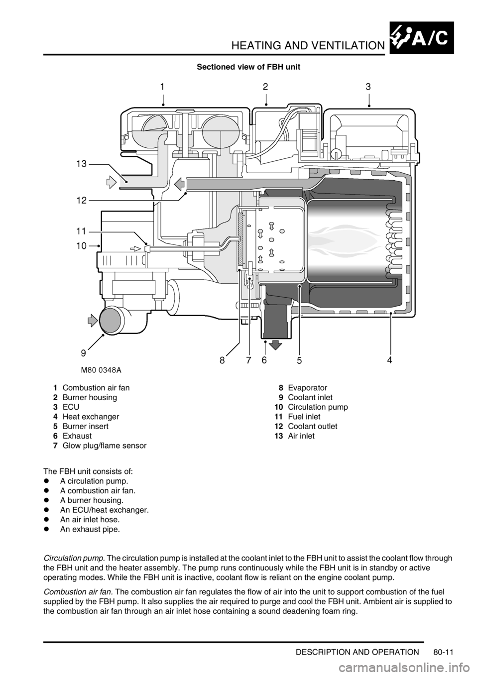
Sectioned view of FBH unit
1Combustion air fan
2Burner housing
3ECU
4Heat exchanger
5Burner insert
6Exhaust
7Glow plug/flame sensor8Evaporator
9Coolant inlet
10Circulation pump
11Fuel inlet
12Coolant outlet
13Air inlet
The FBH unit consists of:
lA circulation pump.
lA combustion air fan.
lA burner housing.
lAn ECU/heat exchanger.
lAn air inlet hose.
lAn exhaust pipe.
Circulation pump. The circulation pump is installed at the coolant inlet to the FBH unit to assist the coolant flow through
the FBH unit and the heater assembly. The pump runs continuously while the FBH unit is in standby or active
operating modes. While the FBH unit is inactive, coolant flow is reliant on the engine coolant pump.
Combustion air fan. The combustion air fan regulates the flow of air into the unit to support combustion of the fuel
supplied by the FBH pump. It also supplies the air required to purge and cool the FBH unit. Ambient air is supplied to
the combustion air fan through an air inlet hose containing a sound deadening foam ring.
Page 1169 of 1529

HEATING AND VENTILATION
80-12DESCRIPTION AND OPERATION
Burner housing. The burner housing contains the burner insert and also incorporates connections for the exhaust
pipe, the coolant inlet from the circulation pump and the coolant outlet to the heater assembly. The exhaust pipe
directs exhaust combustion gases to atmosphere at the bottom of the engine compartment.
The burner insert incorporates the fuel combustion chamber, an evaporator and a glow plug/flame sensor. Fuel from
the FBH fuel pump is supplied to the evaporator, where it evaporates and enters the combustion chamber to mix with
air from the combustion air fan. The glow plug/flame sensor provides the ignition source of the fuel:air mixture and,
once combustion is established, monitors the flame.
ECU/heat exchanger. The ECU controls and monitors operation of the FBH system. Ventilation of the ECU is
provided by an internal flow of air from the combustion air fan. The heat exchanger transfers heat generated by
combustion to the coolant. A sensor in the heat exchanger provides the ECU with an input of heat exchanger casing
temperature, which the ECU relates to coolant temperature and uses to control system operation. The temperature
settings in the ECU are calibrated to compensate for the difference between coolant temperature and the heat
exchanger casing temperature detected by the sensor. Typically: as the coolant temperature increases, the coolant
will be approximately 7 °C (12.6 °F) hotter than the temperature detected by the sensor; as the coolant temperature
decreases, the coolant will be approximately 2 °C (3.6 °F) cooler than the temperature detected by the sensor.
Page 1170 of 1529

HEATING AND VENTILATION
DESCRIPTION AND OPERATION 80-13
Operation
Air distribution
Turning the distribution knob on the control panel turns the control flaps in the heater assembly to direct air to the
corresponding fascia and footwell outlets.
Air temperature
Turning the LH or RH temperature knob on the control panel turns the related blend flaps in the heater assembly. The
blend flaps vary the proportion of air going through the cold air bypass and the heater matrix. The proportion varies,
between full bypass no heat and no bypass full heat, to correspond with the position of the temperature knob.
Blower speed
The blower can be selected off or to run at one of four speeds. While the ignition is on, when the blower switch is set
to positions 1, 2, 3, or 4, ignition power energises the blower relay, which supplies battery power to the blower. At
switch positions 1, 2 and 3, the blower switch also connects the blower to different earth paths through the resistor
pack, to produce corresponding differences of blower operating voltage and speed. At position 4, the blower switch
connects an earth direct to the blower, bypassing the resistor pack, and full battery voltage drives the blower at
maximum speed.
Fresh/Recirculated inlet air
When the recirculated air switch is latched in, the amber indicator LED in the switch illuminates and an earth is
connected to the recirculated air side of the fresh/recirculated air servo motor. The fresh/recirculated air servo motor
then turns the control flaps in the air inlet duct to close the fresh air inlet and open the recirculated air inlets.
When the latch of the recirculated air switch is released, the amber indicator LED in the switch extinguishes and the
earth is switched from the recirculated air side to the fresh air side of the fresh/recirculated air servo motor. The fresh/
recirculated air servo motor then turns the control flaps in the air inlet duct to open the fresh air inlet and close the
recirculated air inlets.
FBH system (where fitted)
The FBH system operates only while the engine is running and the ambient temperature is less than 5 °C (41 °F).
With the engine running and the ambient temperature below 5 °C (41 °F), the air temperature sensor connects the
alternator power supply to the ECU in the FBH unit. On receipt of the alternator power supply, the ECU starts the
circulation pump and, depending on the input from the temperature sensor in the heat exchanger, enters either a
standby or active mode of operation. If the heat exchanger casing temperature is 65 °C (149 °F) or above, the ECU
enters a standby mode of operation. If the heat exchanger casing temperature is below 65 °C (149 °F), the ECU enters
an active mode of operation. In the standby mode, the ECU monitors the heat exchanger casing temperature and
enters the active mode if it drops below 65 °C (149 °F). In the active mode, the ECU initiates a start sequence and
then operates the system at full or part load combustion to provide the required heat input to the coolant.
Start sequence
At the beginning of the start sequence the ECU energises the glow plug function of the glow plug/flame sensor, to
preheat the combustion chamber, and starts the combustion air fan at slow speed. After 30 seconds, the ECU
energises the FBH fuel pump at the starting sequence speed. The fuel delivered by the FBH fuel pump evaporates in
the combustion chamber, mixes with air from the combustion air fan and is ignited by the glow plug/flame sensor. The
ECU then progressively increases the speed of the FBH fuel pump and the combustion air fan to either part or full
load speed, as required by the system. Once full or part load speed is achieved, the ECU switches the glow plug/flame
sensor from the glow plug function to the flame sensing function to monitor combustion. From the beginning of the
start sequence to stable combustion takes approximately 90 seconds for a start to part load combustion and 150
seconds for a start to full load combustion.
Page 1171 of 1529

HEATING AND VENTILATION
80-14DESCRIPTION AND OPERATION
Coolant temperature control
When the ECU first enters the active mode, it initiates a start to full load combustion. Full load combustion continues
until the heat exchanger casing temperature reaches 60 °C (140 °F), when the ECU decreases the speed of the FBH
fuel pump and the combustion air fan to half speed, to produce part load combustion. The ECU maintains part load
combustion while the heat exchanger casing temperature remains between 54 and 65 °C (129 and 149 °F). If the heat
exchanger casing temperature decreases to 54 °C (129 °F), the ECU switches the system to full load combustion
again. If the heat exchanger casing temperature increases to 65 °C (149 °F), the ECU enters a control idle phase of
operation.
On entering the control idle phase, the ECU immediately switches the FBH fuel pump off, to stop combustion, and
starts a timer for the combustion air fan. After a 2 minute cooldown period, the ECU switches the combustion air fan
off and then remains in the control idle phase while the heat exchanger casing temperature remains above 59 °C (138
°F). If the heat exchanger casing temperature decreases to 59 °C (138 °F), within 15 minutes of the ECU entering the
control idle phase, the ECU initiates a start to part load combustion. If more than 15 minutes elapse before the heat
exchanger casing temperature decreases to 59 °C (138 °F), the ECU initiates a start to full load combustion.
In order to limit the build-up of carbon deposits on the glow plug/flame sensor, the ECU also enters the control idle
phase if the continuous part and/or full load combustion time exceeds 72 minutes. After the cooldown period, if the
heat exchanger casing is still in the temperature range that requires additional heat, the ECU initiates an immediate
restart to part or full load combustion, as appropriate.
Shutdown
The FBH system is de-activated when the alternator power supply to the FBH unit is disconnected, either by the
engine stopping or, if the ambient temperature increases to 5 °C (41 °F) or above, by the contacts in the air
temperature sensor opening. If the system is active when the alternator power supply is disconnected, the ECU de-
energises the FBH fuel pump to stop combustion, but continues operation of the combustion air fan and the circulation
pump to cool down the FBH unit. The cool down time depends on the combustion load at the time the alternator power
input is disconnected.
Cool down times
Diagnostics
The ECU in the FBH unit monitors the system for faults. Any faults detected are stored in a volatile memory in the the
ECU, which can be interrogated by Testbook. A maximum of three faults and associated freeze frame data can be
stored at any one time. If a further fault is detected, the oldest fault is overwritten by the new fault.
The ECU also incorporates an error lockout mode of operation that inhibits system operation to prevent serious faults
from causing further damage to the system. In the error lockout mode, the ECU immediately stops the FBH fuel pump,
and stops the combustion air fan and circulation pump after a cool down time of approximately 2 minutes. Error lockout
occurs for start sequence failures and/or combustion flameouts, heat exchanger casing overheat and out of limit input
voltage. The error lockout mode can be cleared using Testbook, or by disconnecting the battery power supply for a
minimum of 10 seconds.
Start failure/flameout. If a start sequence fails to establish combustion, or a flameout occurs after combustion is
established, the ECU immediately initiates another start sequence. The start failure or flameout is also recorded by
an event timer in the ECU. The event timer is increased by one after each start failure or flameout, and decreased by
one if a subsequent start is successful. If the event timer increases to three (over any number of drive cycles), the
ECU enters the error lockout mode.
Heat exchanger casing overheat. To protect the system from excessive temperatures, the ECU enters the error
lockout mode if the heat exchanger casing temperature exceeds 105 °C (221 °F).
Out of limit voltage. The ECU enters the error lockout mode if the battery or alternator power input is less than 10.5 ±
0.3 V for more than 20 seconds, or more than 15.5 ± 0.5 V for more than 6 seconds.
Combustion load Cool down time, seconds
Part 100
Full 175
Page 1191 of 1529

AIR CONDITIONING
82-2DESCRIPTION AND OPERATION
A/C control system component layout
RH drive shown, LH drive similar
1Air temperature control ECU
2Heater coolant temperature sensor
3Evaporator temperature sensor
4Dual pressure switch5Ambient temperature sensor
6Sunlight sensor
7In-car temperature sensor
Page 1198 of 1529

AIR CONDITIONING
DESCRIPTION AND OPERATION 82-9
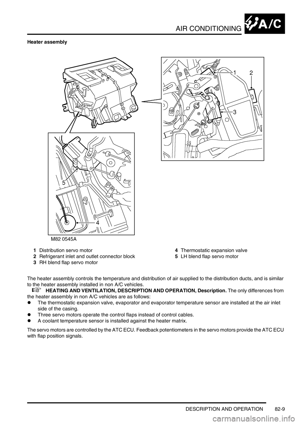
Heater assembly
1Distribution servo motor
2Refrigerant inlet and outlet connector block
3RH blend flap servo motor4Thermostatic expansion valve
5LH blend flap servo motor
The heater assembly controls the temperature and distribution of air supplied to the distribution ducts, and is similar
to the heater assembly installed in non A/C vehicles.
+ HEATING AND VENTILATION, DESCRIPTION AND OPERATION, Description. The only differences from
the heater assembly in non A/C vehicles are as follows:
lThe thermostatic expansion valve, evaporator and evaporator temperature sensor are installed at the air inlet
side of the casing.
lThree servo motors operate the control flaps instead of control cables.
lA coolant temperature sensor is installed against the heater matrix.
The servo motors are controlled by the ATC ECU. Feedback potentiometers in the servo motors provide the ATC ECU
with flap position signals.
Page 1199 of 1529

AIR CONDITIONING
82-10DESCRIPTION AND OPERATION
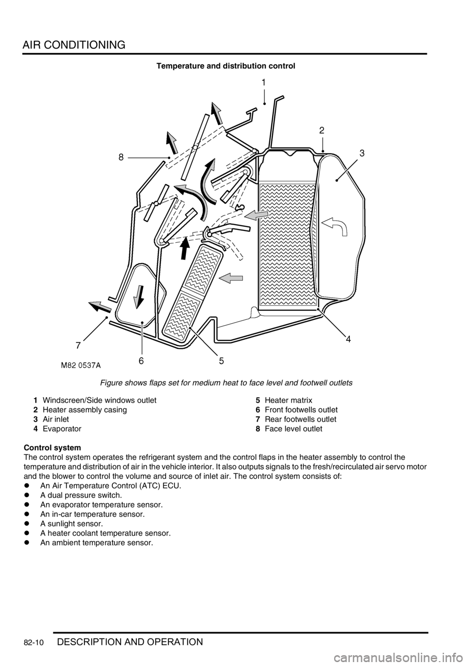
Temperature and distribution control
Figure shows flaps set for medium heat to face level and footwell outlets
1Windscreen/Side windows outlet
2Heater assembly casing
3Air inlet
4Evaporator5Heater matrix
6Front footwells outlet
7Rear footwells outlet
8Face level outlet
Control system
The control system operates the refrigerant system and the control flaps in the heater assembly to control the
temperature and distribution of air in the vehicle interior. It also outputs signals to the fresh/recirculated air servo motor
and the blower to control the volume and source of inlet air. The control system consists of:
lAn Air Temperature Control (ATC) ECU.
lA dual pressure switch.
lAn evaporator temperature sensor.
lAn in-car temperature sensor.
lA sunlight sensor.
lA heater coolant temperature sensor.
lAn ambient temperature sensor.