1999 LAND ROVER DISCOVERY wheel
[x] Cancel search: wheelPage 1140 of 1529
CORROSION PREVENTION AND SEALING
CORROSION PREVENTION 77-4-7
The checks described above are intended to be visual only. It is not intended that the operator should remove trim
panels, finishers, rubbing strips or sound-deadening materials when checking the vehicle for corrosion and paint
damage.
With the vehicle on a lift, and using an inspection or spot lamp, visually check for the following:
lCorrosion damage and damaged paintwork, condition of underbody sealer on front and rear lower panels, sills
and wheel arches;
lDamage to underbody sealer. Corrosion in areas adjacent to suspension mountings and fuel tank fixings.
NOTE: The presence of small blisters in the underbody sealer is acceptable, providing they do not expose bare metal.
Pay special attention to signs of damage caused to panels or corrosion protection material by incorrect jack
positioning.
WARNING: It is essential to follow the correct jacking and lifting procedures.
With the vehicle lowered, visually check for evidence of damage and corrosion on all visible painted areas, in
particular the following:
lFront edge of bonnet;
lVisible flanges in engine compartment;
lLower body and door panels.
Rectify any bodywork damage or evidence of corrosion found during inspection as soon as is practicable, both to
minimise the extent of the damage and to ensure the long term effectiveness of the factory-applied corrosion
prevention treatment. Where the cost of rectification work is the owner's responsibility, the Dealer must advise the
owner and endorse the relevant documentation accordingly.
Where corrosion has become evident and is emanating from beneath a removable component (e.g. trim panel,
window glass, seat etc.), remove the component as required to permit effective rectification.
Underbody protection repairs
Whenever body repairs are carried out, ensure that full sealing and corrosion protection treatments are reinstated.
This applies both to the damaged areas and also to areas where protection has been indirectly impaired, as a result
either of accident damage or repair operations.
Remove corrosion protection from the damaged area before straightening or panel beating. This applies in particular
to panels coated with wax, PVC underbody sealer, sound deadening pads etc.
WARNING: DO NOT use oxy-acetylene gas equipment to remove corrosion prevention materials. Large
volumes of fumes and gases are liberated by these materials when they burn.
NOTE: Equipment for the removal of tough anti-corrosion sealers offers varying degrees of speed and effectiveness.
The compressed air-operated scraper (NOT an air chisel) offers a relatively quiet mechanical method using an
extremely rapid reciprocating action. Move the operating end of the tool along the work surface to remove the material.
The most common method of removal is by means of a hot air blower with integral scraper.
Another tool, and one of the most efficient methods, is the rapid-cutting 'hot knife'. This tool uses a wide blade and is
quick and versatile, able to be used easily in profiled sections where access is otherwise difficult.
Use the following procedure when repairing underbody coatings:
1Remove existing underbody coatings
2After panel repair, clean the affected area with a solvent wipe, and treat bare metal with an etch phosphate
material
3Re-prime the affected area
CAUTION: DO NOT, under any circumstances, apply underbody sealer directly to bare metal surfaces.
4Replace all heat-fusible plugs which have been disturbed. Where such plugs are not available use rubber
grommets of equivalent size, ensuring that they are embedded in sealer
5Mask off all mounting faces from which mechanical components, hoses and pipe clips, have been removed.
Underbody sealer must be applied before such components are refitted
6Brush sealer into all exposed seams
7Spray the affected area with an approved service underbody sealer
8Remove masking from component mounting faces, and touch-in where necessary. Allow adequate drying time
before applying underbody wax
Page 1142 of 1529
CORROSION PREVENTION AND SEALING
SEALING 77-4-9
SEALING
Body Sealing
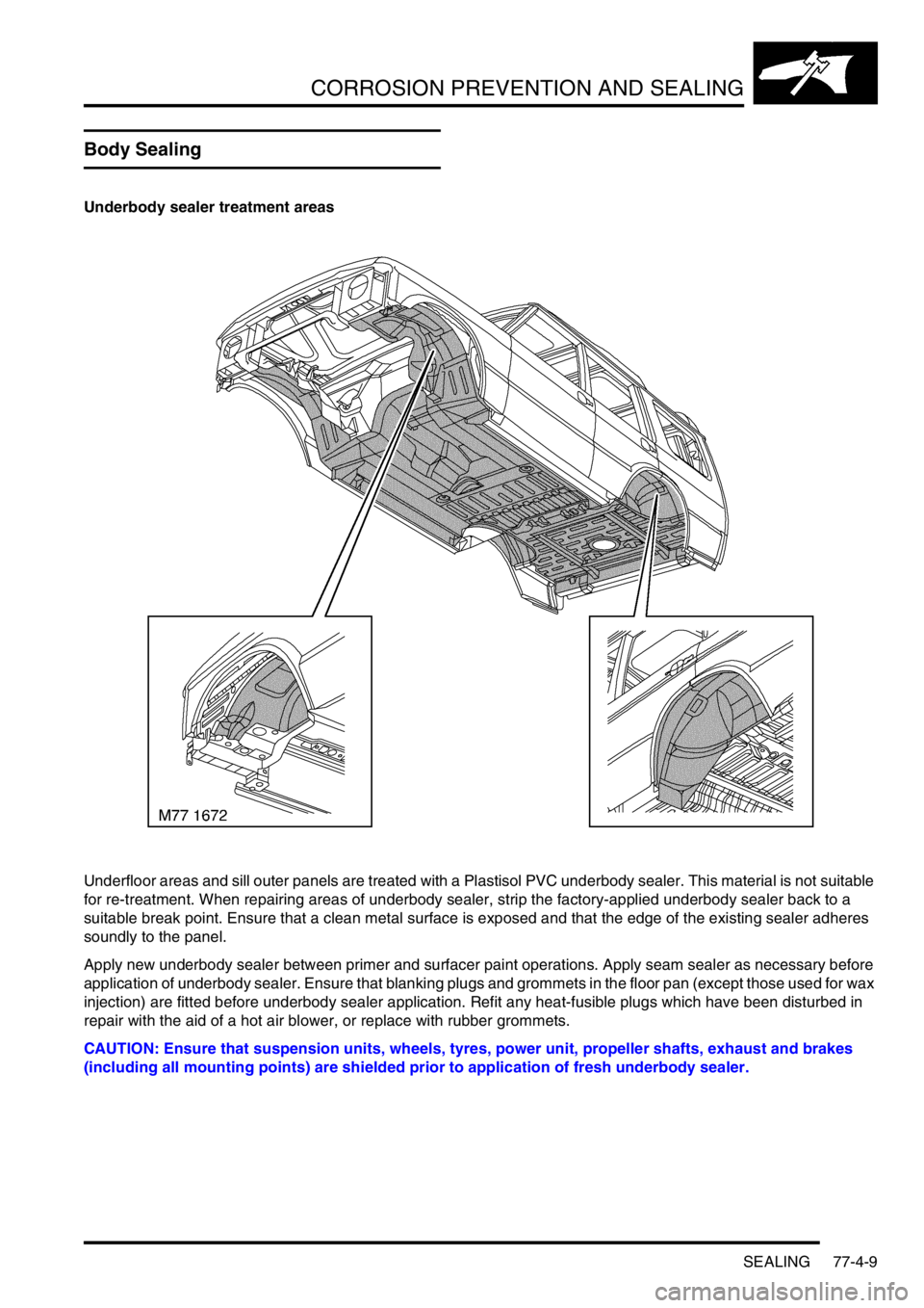
Underbody sealer treatment areas
Underfloor areas and sill outer panels are treated with a Plastisol PVC underbody sealer. This material is not suitable
for re-treatment. When repairing areas of underbody sealer, strip the factory-applied underbody sealer back to a
suitable break point. Ensure that a clean metal surface is exposed and that the edge of the existing sealer adheres
soundly to the panel.
Apply new underbody sealer between primer and surfacer paint operations. Apply seam sealer as necessary before
application of underbody sealer. Ensure that blanking plugs and grommets in the floor pan (except those used for wax
injection) are fitted before underbody sealer application. Refit any heat-fusible plugs which have been disturbed in
repair with the aid of a hot air blower, or replace with rubber grommets.
CAUTION: Ensure that suspension units, wheels, tyres, power unit, propeller shafts, exhaust and brakes
(including all mounting points) are shielded prior to application of fresh underbody sealer.
Page 1151 of 1529
CORROSION PREVENTION AND SEALING
77-4-18 SEALING
Structural adhesive
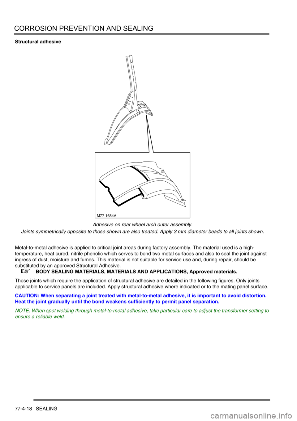
Adhesive on rear wheel arch outer assembly.
Joints symmetrically opposite to those shown are also treated. Apply 3 mm diameter beads to all joints shown.
Metal-to-metal adhesive is applied to critical joint areas during factory assembly. The material used is a high-
temperature, heat cured, nitrile phenolic which serves to bond two metal surfaces and also to seal the joint against
ingress of dust, moisture and fumes. This material is not suitable for service use and, during repair, should be
substituted by an approved Structural Adhesive.
+ BODY SEALING MATERIALS, MATERIALS AND APPLICATIONS, Approved materials.
Those joints which require the application of structural adhesive are detailed in the following figures. Only joints
applicable to service panels are included. Apply structural adhesive where indicated or to the mating panel surface.
CAUTION: When separating a joint treated with metal-to-metal adhesive, it is important to avoid distortion.
Heat the joint gradually until the bond weakens sufficiently to permit panel separation.
NOTE: When spot welding through metal-to-metal adhesive, take particular care to adjust the transformer setting to
ensure a reliable weld.
M77 1684A
Page 1164 of 1529
HEATING AND VENTILATION
DESCRIPTION AND OPERATION 80-7
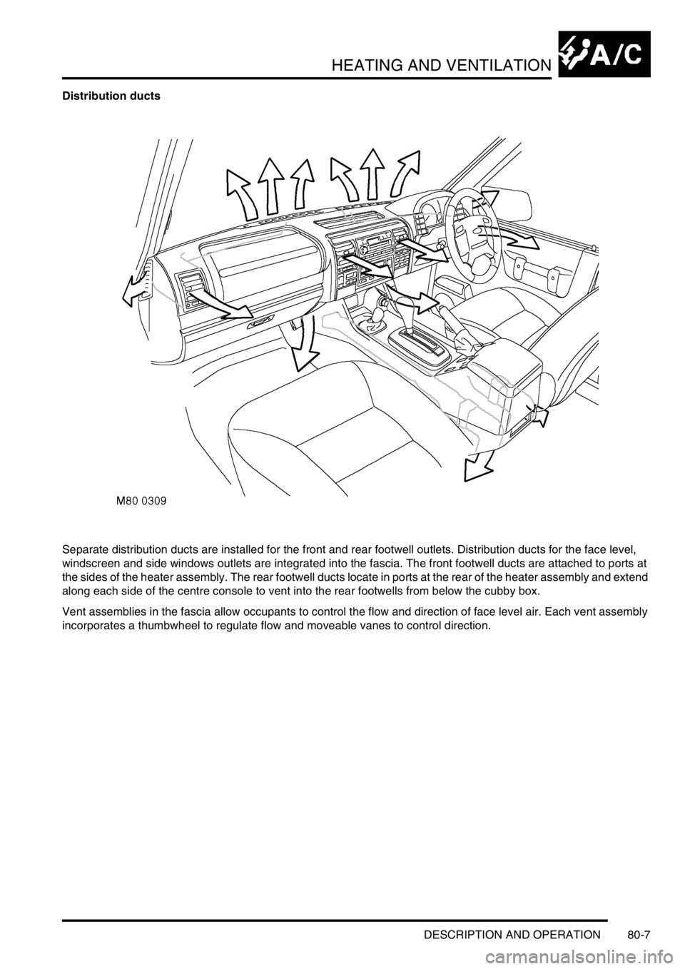
Distribution ducts
Separate distribution ducts are installed for the front and rear footwell outlets. Distribution ducts for the face level,
windscreen and side windows outlets are integrated into the fascia. The front footwell ducts are attached to ports at
the sides of the heater assembly. The rear footwell ducts locate in ports at the rear of the heater assembly and extend
along each side of the centre console to vent into the rear footwells from below the cubby box.
Vent assemblies in the fascia allow occupants to control the flow and direction of face level air. Each vent assembly
incorporates a thumbwheel to regulate flow and moveable vanes to control direction.
Page 1214 of 1529

AIR CONDITIONING
DESCRIPTION AND OPERATION 82-25
Blower
The blower controls the volume of air being supplied to the distribution outlets. The blower is an open hub, centrifugal
fan powered by an electric motor. A dust filter is installed over the fan inlet. The blower switch on the control panel
and the resistor pack control the operation of the blower, which can be selected to run at one of four speeds.
Resistor pack
The resistor pack supplies reduced voltages to the blower motor for blower speeds 1, 2 and 3. For blower speed 4,
the resistor pack is bypassed and battery voltage drives the motor at full speed. The pack is installed in the air outlet
from the blower fan, so that any heat generated is dissipated by the air flow.
Distribution system
Air ducts
Ducts connected to the rear evaporator/blower motor assembly distribute air to five vent assemblies in the roof.
Vent assemblies
The vent assemblies allow occupants to control the flow and direction of air. Each vent assembly incorporates a
thumbwheel to regulate flow and moveable vanes to control direction.
Rear control system
The control system operates the blower to control the operation of the rear A/C. The control system consists of two
control switches and a rear blower relay.
Control switches
A rear A/C switch and a blower speed switch are installed on a control panel in the roof lining. The A/C switch is a
latching pushswitch with an amber indicator lamp which illuminates when rear A/C is selected on. The blower speed
switch is a slide switch with a positive detent at each of four speed positions (there is no off position).
Rear blower relay
The rear blower relay controls the electrical supply to the blower.
Page 1237 of 1529
WIPERS AND WASHERS
84-2 DESCRIPTION AND OPERATION
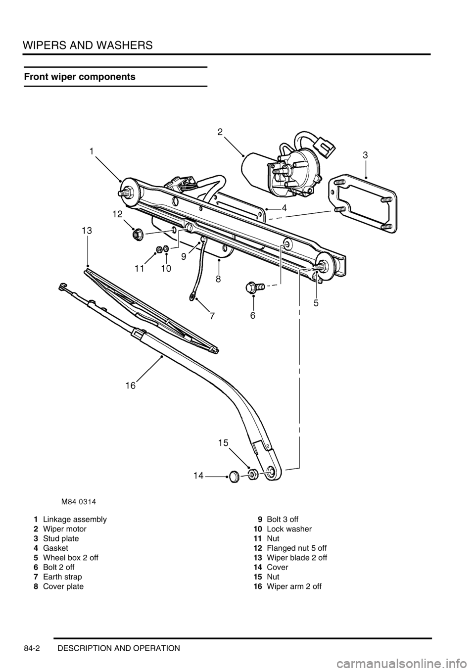
Front wiper components
1Linkage assembly
2Wiper motor
3Stud plate
4Gasket
5Wheel box 2 off
6Bolt 2 off
7Earth strap
8Cover plate9Bolt 3 off
10Lock washer
11Nut
12Flanged nut 5 off
13Wiper blade 2 off
14Cover
15Nut
16Wiper arm 2 off
Page 1243 of 1529

WIPERS AND WASHERS
84-8 DESCRIPTION AND OPERATION
Description
General
All markets have a common wiper system with headlamp powerwash as an option.
The wipers system comprises two front wipers and one rear wiper which are powered by electric motors. A washer
reservoir is located in the front left hand wheel arch and is fitted with two electric pumps. Each pump supplies washer
fluid to either the front or rear screens. On certain models, a third pump can be fitted to operate a headlamp power
wash function. Operation of the front and rear wipers and washers is controlled by the driver using switches located
on a steering column stalk and push button switches on the fascia.
Control of the wipers and washers is achieved by the following components:
lBCU.
lIDM.
lFront wiper relay.
lFront wash/ wipe switch.
lVariable delay switch.
lFront wiper motor assembly.
lFront washer pump motor.
lRear wiper relay.
lRear wiper switch.
lRear washer switch.
lRear wiper motor.
lRear washer pump motor.
Both the Body Control Unit (BCU) and the Intelligent Driver Module (IDM) control the wiper system. The BCU controls
the time delay function of the wiper system and is located below and behind the passenger glovebox. During engine
cranking the BCU prevents wiper functions. Two relays are located in the passenger compartment fusebox. The
relays control the delay operation of the front and rear wipers. The relays are an integral part of the fusebox and
cannot be renewed separately.
Power for the wiper system is supplied by the IDM, which is integral with the passenger fusebox and cannot be
renewed as a component. A serial communication link allows communication between the IDM and the BCU.
The system has diagnostic capabilities through TestBook.
Front wipers
The two front windscreen wipers are operated by a linkage assembly and an electric motor located under the plenum
grill below the windscreen. The linkage and motor assembly is handed for left and right hand drive vehicles. The motor
is an integral part of the linkage and cannot be replaced separately.
The linkage comprises a pressed steel mounting plate which provides for the attachment of a wheel box at each end.
The mounting plate is secured to the bulkhead with flanged nuts which attach to a stud plate located behind the
bulkhead. A link arm is attached to each wheel box by a short link and secured with circlips. The link arm has an
attachment hole centrally located along its length for the electric motor drive link.
The electric motor is mounted in a recess in the bulkhead below a sealed cover plate. The drive spindle of the motor
protrudes through the cover plate and is fitted with a link. The link is attached to a tapered spline on the motor spindle
and is secured with a lock washer and nut. The opposite end of the link is attached to the central attachment point on
the link arm and secured with a circlip.
Each wheel box has a taper splined shaft which allows for the attachment of the wiper arm which is secured with a
washer and nut. The shaft of each wheel box is passed through a rubber sealed aperture in the plenum. The wiper
arm attachment to the splined shaft has a pivot to which the remainder of the arm is attached. The two parts of the
arm are connected by a spring which controls the pressure of the blade on the screen to a predetermined amount.
The wiper blades are attached to the wiper arms with a clips that allow the blade to pivot. Each wiper blade comprises
a number of levers and yokes to which the rubber wiper is attached. The levers and yokes ensure that the pressure
applied by the arm spring is distributed evenly along the full length of the blade. The rubber wiper is held in the yokes
by a pair of stainless steel strips which also contribute to the even distribution of spring pressure along the blade. The
driver's side wiper blade is fitted with an aerofoil which presses the blade onto the screen at high speed. This prevents
the blade from lifting off the screen and maintains the wiping performance.
Page 1248 of 1529
WIPERS AND WASHERS
DESCRIPTION AND OPERATION 84-13
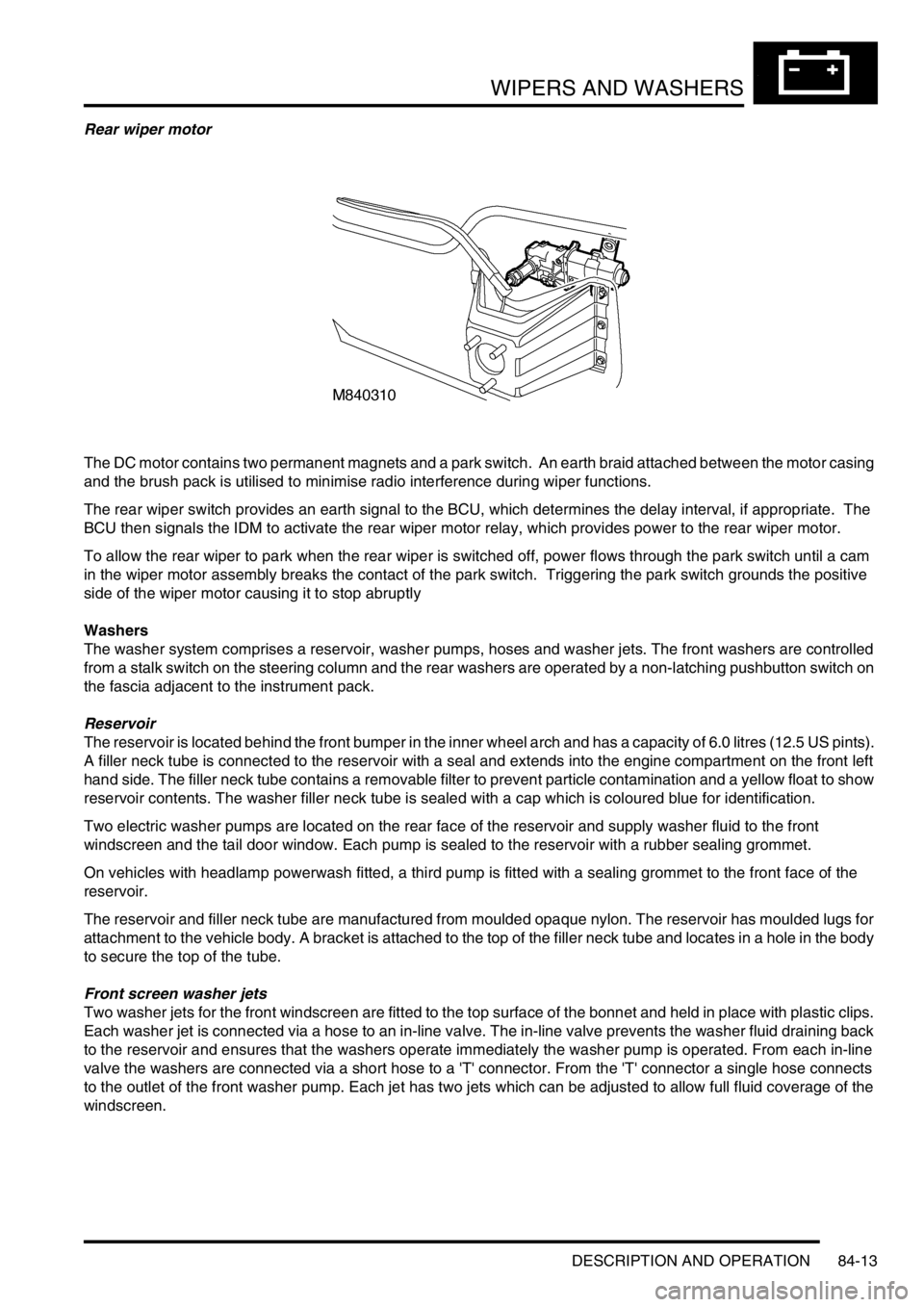
Rear wiper motor
The DC motor contains two permanent magnets and a park switch. An earth braid attached between the motor casing
and the brush pack is utilised to minimise radio interference during wiper functions.
The rear wiper switch provides an earth signal to the BCU, which determines the delay interval, if appropriate. The
BCU then signals the IDM to activate the rear wiper motor relay, which provides power to the rear wiper motor.
To allow the rear wiper to park when the rear wiper is switched off, power flows through the park switch until a cam
in the wiper motor assembly breaks the contact of the park switch. Triggering the park switch grounds the positive
side of the wiper motor causing it to stop abruptly
Washers
The washer system comprises a reservoir, washer pumps, hoses and washer jets. The front washers are controlled
from a stalk switch on the steering column and the rear washers are operated by a non-latching pushbutton switch on
the fascia adjacent to the instrument pack.
Reservoir
The reservoir is located behind the front bumper in the inner wheel arch and has a capacity of 6.0 litres (12.5 US pints).
A filler neck tube is connected to the reservoir with a seal and extends into the engine compartment on the front left
hand side. The filler neck tube contains a removable filter to prevent particle contamination and a yellow float to show
reservoir contents. The washer filler neck tube is sealed with a cap which is coloured blue for identification.
Two electric washer pumps are located on the rear face of the reservoir and supply washer fluid to the front
windscreen and the tail door window. Each pump is sealed to the reservoir with a rubber sealing grommet.
On vehicles with headlamp powerwash fitted, a third pump is fitted with a sealing grommet to the front face of the
reservoir.
The reservoir and filler neck tube are manufactured from moulded opaque nylon. The reservoir has moulded lugs for
attachment to the vehicle body. A bracket is attached to the top of the filler neck tube and locates in a hole in the body
to secure the top of the tube.
Front screen washer jets
Two washer jets for the front windscreen are fitted to the top surface of the bonnet and held in place with plastic clips.
Each washer jet is connected via a hose to an in-line valve. The in-line valve prevents the washer fluid draining back
to the reservoir and ensures that the washers operate immediately the washer pump is operated. From each in-line
valve the washers are connected via a short hose to a 'T' connector. From the 'T' connector a single hose connects
to the outlet of the front washer pump. Each jet has two jets which can be adjusted to allow full fluid coverage of the
windscreen.