1999 LAND ROVER DISCOVERY wheel
[x] Cancel search: wheelPage 1479 of 1529

NAVIGATION SYSTEM
87-26 DESCRIPTION AND OPERATION
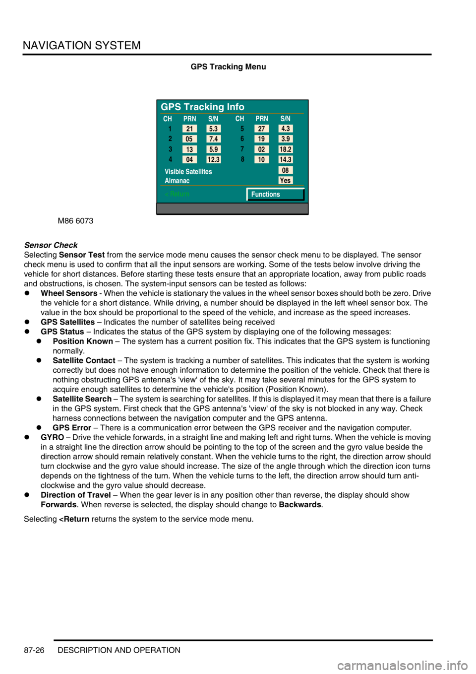
GPS Tracking Menu
Sensor Check
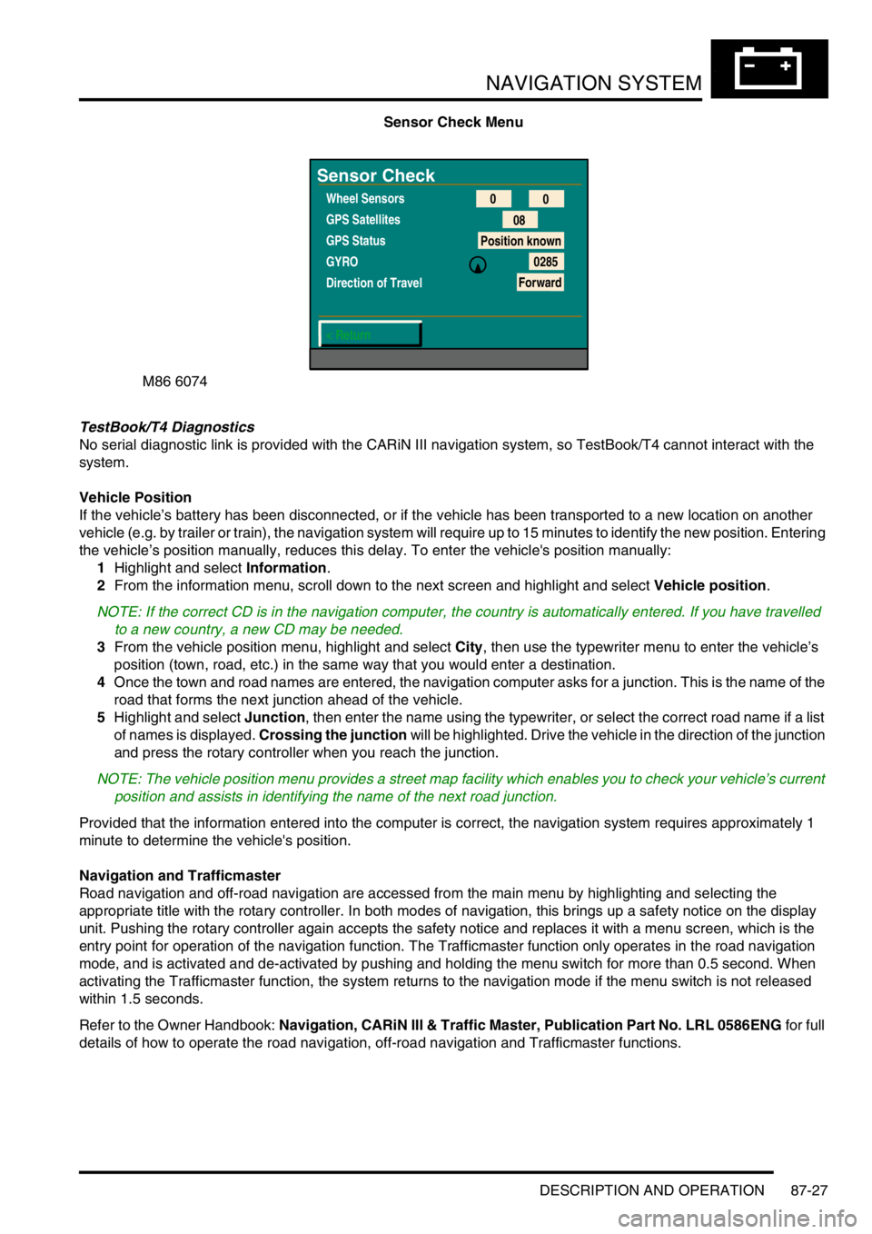
Selecting Sensor Test from the service mode menu causes the sensor check menu to be displayed. The sensor
check menu is used to confirm that all the input sensors are working. Some of the tests below involve driving the
vehicle for short distances. Before starting these tests ensure that an appropriate location, away from public roads
and obstructions, is chosen. The system-input sensors can be tested as follows:
lWheel Sensors - When the vehicle is stationary the values in the wheel sensor boxes should both be zero. Drive
the vehicle for a short distance. While driving, a number should be displayed in the left wheel sensor box. The
value in the box should be proportional to the speed of the vehicle, and increase as the speed increases.
lGPS Satellites – Indicates the number of satellites being received
lGPS Status – Indicates the status of the GPS system by displaying one of the following messages:
lPosition Known – The system has a current position fix. This indicates that the GPS system is functioning
normally.
lSatellite Contact – The system is tracking a number of satellites. This indicates that the system is working
correctly but does not have enough information to determine the position of the vehicle. Check that there is
nothing obstructing GPS antenna's 'view' of the sky. It may take several minutes for the GPS system to
acquire enough satellites to determine the vehicle's position (Position Known).
lSatellite Search – The system is searching for satellites. If this is displayed it may mean that there is a failure
in the GPS system. First check that the GPS antenna's 'view' of the sky is not blocked in any way. Check
harness connections between the navigation computer and the GPS antenna.
lGPS Error – There is a communication error between the GPS receiver and the navigation computer.
lGYRO – Drive the vehicle forwards, in a straight line and making left and right turns. When the vehicle is moving
in a straight line the direction arrow should be pointing to the top of the screen and the gyro value beside the
direction arrow should remain relatively constant. When the vehicle turns to the right, the direction arrow should
turn clockwise and the gyro value should increase. The size of the angle through which the direction icon turns
depends on the tightness of the turn. When the vehicle turns to the left, the direction arrow should turn anti-
clockwise and the gyro value should decrease.
lDirection of Travel – When the gear lever is in any position other than reverse, the display should show
Forwards. When reverse is selected, the display should change to Backwards.
Selecting
GPS Tracking Info
1
2
3
4
Visible Satellites
Almanac
< Return
08
Yes
Functions 5.3 21
7.4 05
5.9
13
12.3
04CHPRN
S/N
CHPRN
S/N
4.3
27
3.9 19
18.2 02
14.3 10 5
6
7
8
Page 1480 of 1529

NAVIGATION SYSTEM
DESCRIPTION AND OPERATION 87-27
Sensor Check Menu
TestBook/T4 Diagnostics
No serial diagnostic link is provided with the CARiN III navigation system, so TestBook/T4 cannot interact with the
system.
Vehicle Position
If the vehicle’s battery has been disconnected, or if the vehicle has been transported to a new location on another
vehicle (e.g. by trailer or train), the navigation system will require up to 15 minutes to identify the new position. Entering
the vehicle’s position manually, reduces this delay. To enter the vehicle's position manually:
1Highlight and select Information.
2From the information menu, scroll down to the next screen and highlight and select Vehicle position.
NOTE: If the correct CD is in the navigation computer, the country is automatically entered. If you have travelled
to a new country, a new CD may be needed.
3From the vehicle position menu, highlight and select City, then use the typewriter menu to enter the vehicle’s
position (town, road, etc.) in the same way that you would enter a destination.
4Once the town and road names are entered, the navigation computer asks for a junction. This is the name of the
road that forms the next junction ahead of the vehicle.
5Highlight and select Junction, then enter the name using the typewriter, or select the correct road name if a list
of names is displayed. Crossing the junction will be highlighted. Drive the vehicle in the direction of the junction
and press the rotary controller when you reach the junction.
NOTE: The vehicle position menu provides a street map facility which enables you to check your vehicle’s current
position and assists in identifying the name of the next road junction.
Provided that the information entered into the computer is correct, the navigation system requires approximately 1
minute to determine the vehicle's position.
Navigation and Trafficmaster
Road navigation and off-road navigation are accessed from the main menu by highlighting and selecting the
appropriate title with the rotary controller. In both modes of navigation, this brings up a safety notice on the display
unit. Pushing the rotary controller again accepts the safety notice and replaces it with a menu screen, which is the
entry point for operation of the navigation function. The Trafficmaster function only operates in the road navigation
mode, and is activated and de-activated by pushing and holding the menu switch for more than 0.5 second. When
activating the Trafficmaster function, the system returns to the navigation mode if the menu switch is not released
within 1.5 seconds.
Refer to the Owner Handbook: Navigation, CARiN III & Traffic Master, Publication Part No. LRL 0586ENG for full
details of how to operate the road navigation, off-road navigation and Trafficmaster functions.
M86 6074
Sensor Check
Wheel Sensors
GPS Satellites
GPS Status
GYRO
Direction of Travel
< Return0
0
08
Position known
0285
Forward
Page 1506 of 1529

INSTRUMENTS
DESCRIPTION AND OPERATION 88-23
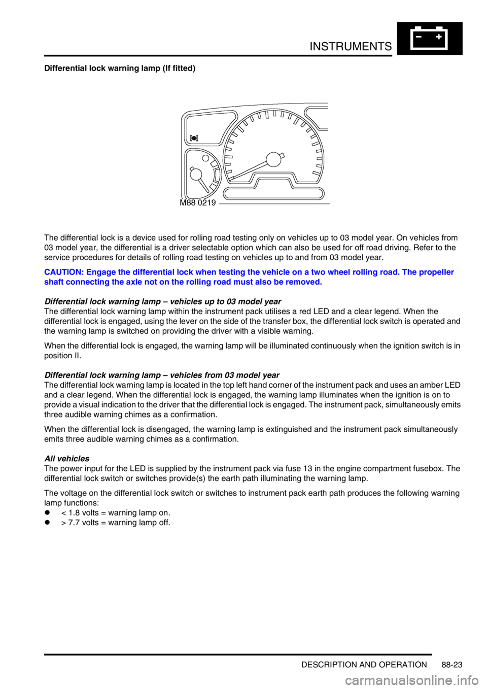
Differential lock warning lamp (If fitted)
The differential lock is a device used for rolling road testing only on vehicles up to 03 model year. On vehicles from
03 model year, the differential is a driver selectable option which can also be used for off road driving. Refer to the
service procedures for details of rolling road testing on vehicles up to and from 03 model year.
CAUTION: Engage the differential lock when testing the vehicle on a two wheel rolling road. The propeller
shaft connecting the axle not on the rolling road must also be removed.
Differential lock warning lamp – vehicles up to 03 model year
The differential lock warning lamp within the instrument pack utilises a red LED and a clear legend. When the
differential lock is engaged, using the lever on the side of the transfer box, the differential lock switch is operated and
the warning lamp is switched on providing the driver with a visible warning.
When the differential lock is engaged, the warning lamp will be illuminated continuously when the ignition switch is in
position II.
Differential lock warning lamp – vehicles from 03 model year
The differential lock warning lamp is located in the top left hand corner of the instrument pack and uses an amber LED
and a clear legend. When the differential lock is engaged, the warning lamp illuminates when the ignition is on to
provide a visual indication to the driver that the differential lock is engaged. The instrument pack, simultaneously emits
three audible warning chimes as a confirmation.
When the differential lock is disengaged, the warning lamp is extinguished and the instrument pack simultaneously
emits three audible warning chimes as a confirmation.
All vehicles
The power input for the LED is supplied by the instrument pack via fuse 13 in the engine compartment fusebox. The
differential lock switch or switches provide(s) the earth path illuminating the warning lamp.
The voltage on the differential lock switch or switches to instrument pack earth path produces the following warning
lamp functions:
l< 1.8 volts = warning lamp on.
l> 7.7 volts = warning lamp off.