Page 651 of 1529
AUTOMATIC GEARBOX - ZF4HP22 - 24
44-54 REPAIRS
Pressure regulator
$% 44.40.22
Remove
1.Remove valve body assembly.
+ AUTOMATIC GEARBOX - ZF4HP22
- 24, REPAIRS, Valve body assembly.
2.Release and remove clip securing pressure
regulator solenoid valve harness to valve body.
3.Disconnect multiplug from pressure regulator
solenoid valve.
4.Remove 5 Torx screws securing pressure
regulator to valve body and remove pressure
regulator.Refit
1.Clean pressure regulator and mating face with
a lint free cloth.
2.Position pressure regulator to valve body, fit
Torx screws and tighten to 8 Nm (6 lbf.ft).
3.Connect multiplug to pressure regulator
solenoid valve, fit clip and secure harness to
valve body.
4.Fit valve body assembly.
+ AUTOMATIC GEARBOX - ZF4HP22
- 24, REPAIRS, Valve body assembly.
M44 1351
3
Page 652 of 1529
AUTOMATIC GEARBOX - ZF4HP22 - 24
REPAIRS 44-55
Lock-up solenoid valve (MV 3)
$% 44.15.35
Remove
1.Remove valve body assembly.
+ AUTOMATIC GEARBOX - ZF4HP22
- 24, REPAIRS, Valve body assembly.
2.Disconnect multiplug from lock-up solenoid
valve and release harness from clip.
3.Remove Torx screw and retaining fork securing
solenoid valve to valve body.
4.Remove solenoid valve from valve body.Refit
1.Clean lock-up solenoid valve with lint free cloth.
2.Position solenoid valve in valve body.
3.Position retaining fork, fit and tighten Torx
screw to 8 Nm (6 lbf.ft).
4.Connect multiplug to lock-up solenoid valve
and secure harness in clip.
5.Fit valve body assembly.
+ AUTOMATIC GEARBOX - ZF4HP22
- 24, REPAIRS, Valve body assembly.
M44 1354A
2
3
4
Page 653 of 1529

AUTOMATIC GEARBOX - ZF4HP22 - 24
44-56 REPAIRS
Solenoids - shift control valves
(MV 1 & 2)
$% 44.15.45
Remove
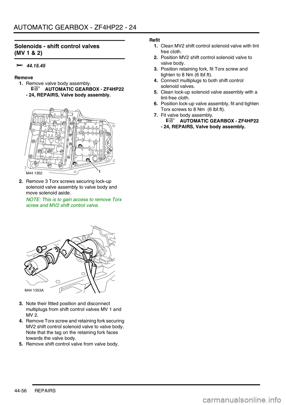
1.Remove valve body assembly.
+ AUTOMATIC GEARBOX - ZF4HP22
- 24, REPAIRS, Valve body assembly.
2.Remove 3 Torx screws securing lock-up
solenoid valve assembly to valve body and
move solenoid aside.
NOTE: This is to gain access to remove Torx
screw and MV2 shift control valve.
3.Note their fitted position and disconnect
multiplugs from shift control valves MV 1 and
MV 2.
4.Remove Torx screw and retaining fork securing
MV2 shift control solenoid valve to valve body.
Note that the tag on the retaining fork faces
towards the valve body.
5.Remove shift control valve from valve body.Refit
1.Clean MV2 shift control solenoid valve with lint
free cloth.
2.Position MV2 shift control solenoid valve to
valve body.
3.Position retaining fork, fit Torx screw and
tighten to 8 Nm (6 lbf.ft).
4.Connect multiplugs to both shift control
solenoid valves.
5.Clean lock-up solenoid valve assembly with a
lint-free cloth.
6.Position lock-up valve assembly, fit and tighten
Torx screws to 8 Nm (6 lbf.ft).
7.Fit valve body assembly.
+ AUTOMATIC GEARBOX - ZF4HP22
- 24, REPAIRS, Valve body assembly.
M44 13521
M44 1353A
Page 654 of 1529

AUTOMATIC GEARBOX - ZF4HP22 - 24
REPAIRS 44-57
Harness - solenoid valves
$% 44.15.52
Remove
1.Remove valve body assembly.
+ AUTOMATIC GEARBOX - ZF4HP22
- 24, REPAIRS, Valve body assembly.
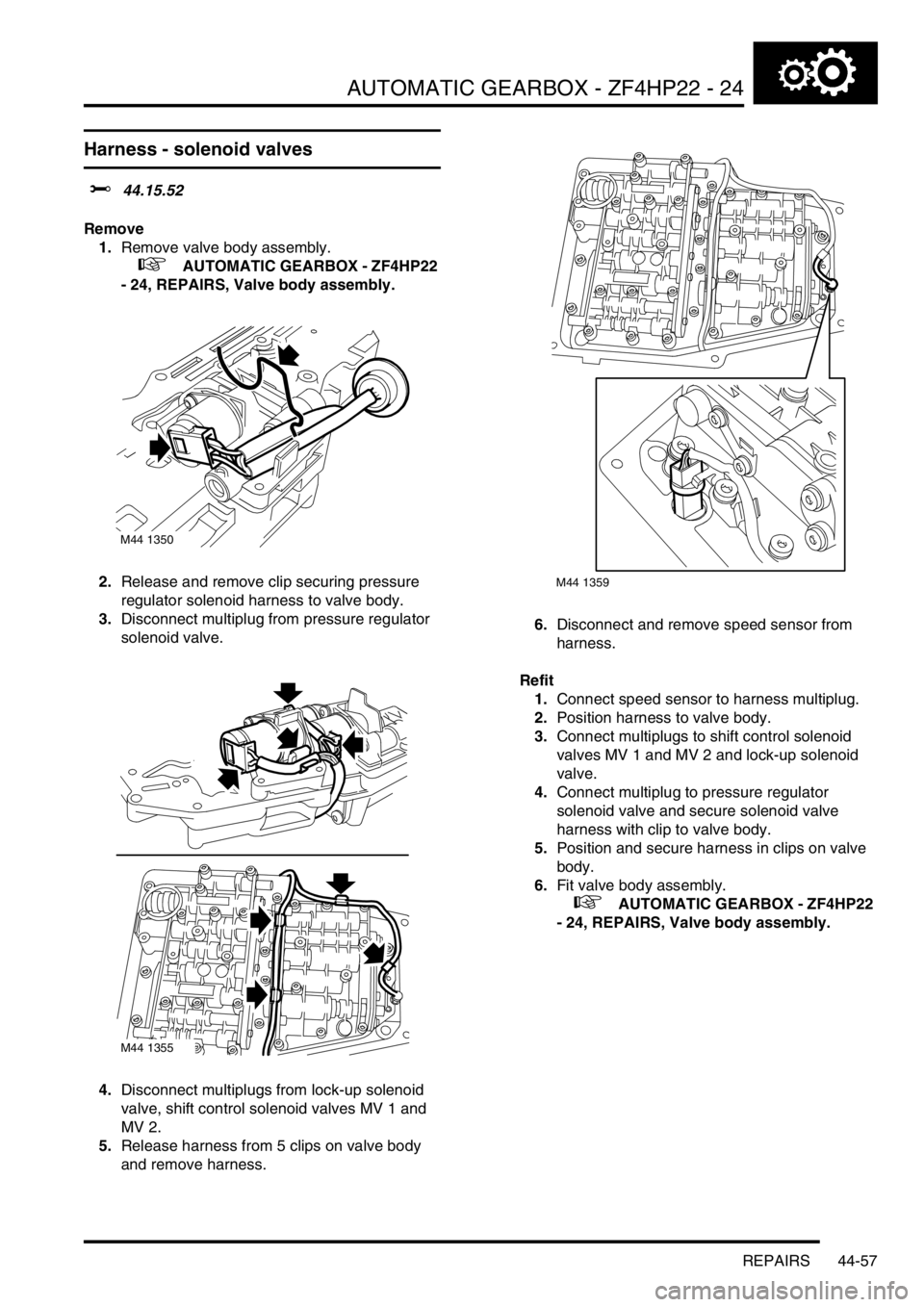
2.Release and remove clip securing pressure
regulator solenoid harness to valve body.
3.Disconnect multiplug from pressure regulator
solenoid valve.
4.Disconnect multiplugs from lock-up solenoid
valve, shift control solenoid valves MV 1 and
MV 2.
5.Release harness from 5 clips on valve body
and remove harness.6.Disconnect and remove speed sensor from
harness.
Refit
1.Connect speed sensor to harness multiplug.
2.Position harness to valve body.
3.Connect multiplugs to shift control solenoid
valves MV 1 and MV 2 and lock-up solenoid
valve.
4.Connect multiplug to pressure regulator
solenoid valve and secure solenoid valve
harness with clip to valve body.
5.Position and secure harness in clips on valve
body.
6.Fit valve body assembly.
+ AUTOMATIC GEARBOX - ZF4HP22
- 24, REPAIRS, Valve body assembly.
M44 1350
M44 1355
M44 1359
Page 655 of 1529
AUTOMATIC GEARBOX - ZF4HP22 - 24
44-58 REPAIRS
Electronic control unit - automatic
transmission
$% 44.15.46
Remove
1.Release fixings and remove battery cover.
2.Disconnect battery earth lead.
3.Remove 3 screws and trim clip securing lower
trim casing to LH front seat.
4.Remove 3 nuts securing speaker power
amplifier bracket to the body.
5.Disconnect multiplug from automatic
transmission ECU located on underside of
amplifier mounting bracket.6.Remove 2 nuts securing ECU to mounting
bracket and remove ECU.
Refit
1.Position ECU to mounting bracket and secure
with nuts.
2.Connect multiplug to ECU.
3.Position speaker power amplifier mounting
bracket to body and secure with nuts.
4.Position lower trim casing to seat and secure
with screws and trim clip.
5.Connect battery earth lead.
6.Fit battery cover and secure fixings.
Page 660 of 1529

PROPELLER SHAFTS
REPAIRS 47-5
REPAIRS
Propeller shaft - front
$% 47.15.02
Remove
1.Raise front of vehicle.
WARNING: Do not work on or under a
vehicle supported only by a jack. Always
support the vehicle on safety stands.
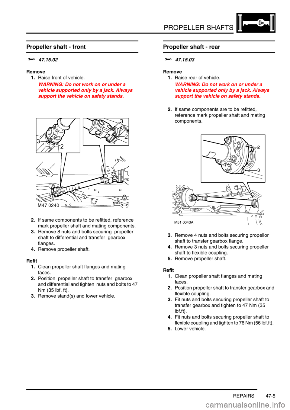
2.If same components to be refitted, reference
mark propeller shaft and mating components.
3.Remove 8 nuts and bolts securing propeller
shaft to differential and transfer gearbox
flanges.
4.Remove propeller shaft.
Refit
1.Clean propeller shaft flanges and mating
faces.
2.Position propeller shaft to transfer gearbox
and differential and tighten nuts and bolts to 47
Nm (35 lbf. ft).
3.Remove stand(s) and lower vehicle.
Propeller shaft - rear
$% 47.15.03
Remove
1.Raise rear of vehicle.
WARNING: Do not work on or under a
vehicle supported only by a jack. Always
support the vehicle on safety stands.
2.If same components are to be refitted,
reference mark propeller shaft and mating
components.
3.Remove 4 nuts and bolts securing propellor
shaft to transfer gearbox flange.
4.Remove 3 nuts and bolts securing propeller
shaft to flexible coupling.
5.Remove propeller shaft.
Refit
1.Clean propeller shaft flanges and mating
faces.
2.Position propeller shaft to transfer gearbox and
flexible coupling.
3.Fit nuts and bolts securing propeller shaft to
transfer gearbox and tighten to 47 Nm (35
lbf.ft).
4.Fit nuts and bolts securing propeller shaft to
flexible coupling and tighten to 76 Nm (56 lbf.ft).
5.Lower vehicle.
M51 0043A
2
3
Page 856 of 1529
BRAKES
DESCRIPTION AND OPERATION 70-3
1ABS sensor
2ABS modulator
3Return pump relay
4SLABS ECU
5Brake lamp relay
6Centre high mounted stop lamp
7LH brake lamp
8RH brake lamp
9Instrument pack10Body control unit
11Reverse lamp switch (manual gearbox)
12Diagnostic socket
13HDC switch
14Transmission high/low switch
15Centre differential lock switch
16Engine control module
17Battery power supply
18Ignition power supply
Page 870 of 1529

BRAKES
DESCRIPTION AND OPERATION 70-17
SLABS ECU
The SLABS ECU is attached to a bracket behind the front passenger glovebox. Brake related inputs are processed
by the SLABS ECU, which then outputs control signals to the ABS modulator. Five electrical connectors interface the
SLABS ECU with the vehicle wiring.
SLABS ECU connector pin details
Connector/Pin
No.Description Input/Output
C0504
1 Battery supply Input
2 Ignition supply Input
3 Road speed Output
4 Rough road (V8 models only) Output
5 K line (diagnostics) Input/Output
7 Reverse gear Input
8 Return pump monitor Input
9 Brake warning lamp Output
10 Engine data (throttle position, torque, engine type, gearbox type) Input
11 Transfer box range Input
12 Earth-
13 ETC warning lamp Output
14 HDC switch Input
15 Neutral selected (automatic gearbox only) Input
16 HDC fault warning lamp Output
17 HDC information warning lamp Output
18 ABS warning lamp Output
C0505
1 Front left wheel speed Input
2 Front left wheel speed Input
3 Rear right wheel speed Input
4 Front right wheel speed Input
5 Front right wheel speed Input
6 Rear right wheel speed Input
7 Rear left wheel speed Input
8 Rear left wheel speed Input
C0506
1 Front left outlet solenoid valve Output
2 Front left inlet solenoid valve Output
3Earth-
4 Front right outlet solenoid valve Output