Page 1490 of 1529
INSTRUMENTS
DESCRIPTION AND OPERATION 88-7
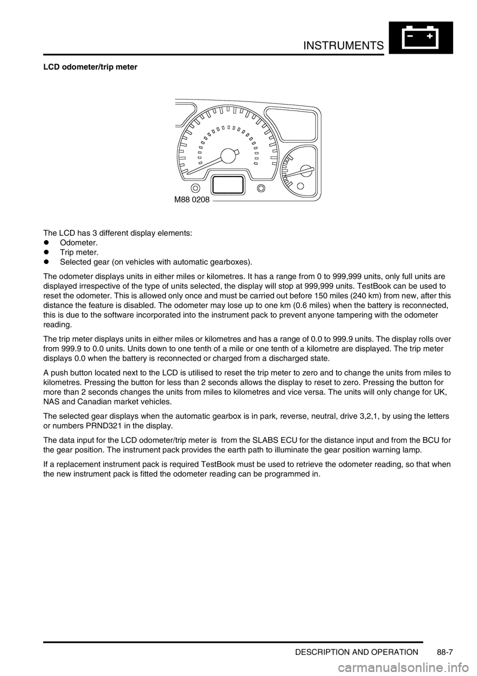
LCD odometer/trip meter
The LCD has 3 different display elements:
lOdometer.
lTrip meter.
lSelected gear (on vehicles with automatic gearboxes).
The odometer displays units in either miles or kilometres. It has a range from 0 to 999,999 units, only full units are
displayed irrespective of the type of units selected, the display will stop at 999,999 units. TestBook can be used to
reset the odometer. This is allowed only once and must be carried out before 150 miles (240 km) from new, after this
distance the feature is disabled. The odometer may lose up to one km (0.6 miles) when the battery is reconnected,
this is due to the software incorporated into the instrument pack to prevent anyone tampering with the odometer
reading.
The trip meter displays units in either miles or kilometres and has a range of 0.0 to 999.9 units. The display rolls over
from 999.9 to 0.0 units. Units down to one tenth of a mile or one tenth of a kilometre are displayed. The trip meter
displays 0.0 when the battery is reconnected or charged from a discharged state.
A push button located next to the LCD is utilised to reset the trip meter to zero and to change the units from miles to
kilometres. Pressing the button for less than 2 seconds allows the display to reset to zero. Pressing the button for
more than 2 seconds changes the units from miles to kilometres and vice versa. The units will only change for UK,
NAS and Canadian market vehicles.
The selected gear displays when the automatic gearbox is in park, reverse, neutral, drive 3,2,1, by using the letters
or numbers PRND321 in the display.
The data input for the LCD odometer/trip meter is from the SLABS ECU for the distance input and from the BCU for
the gear position. The instrument pack provides the earth path to illuminate the gear position warning lamp.
If a replacement instrument pack is required TestBook must be used to retrieve the odometer reading, so that when
the new instrument pack is fitted the odometer reading can be programmed in.
Page 1495 of 1529
INSTRUMENTS
88-12 DESCRIPTION AND OPERATION
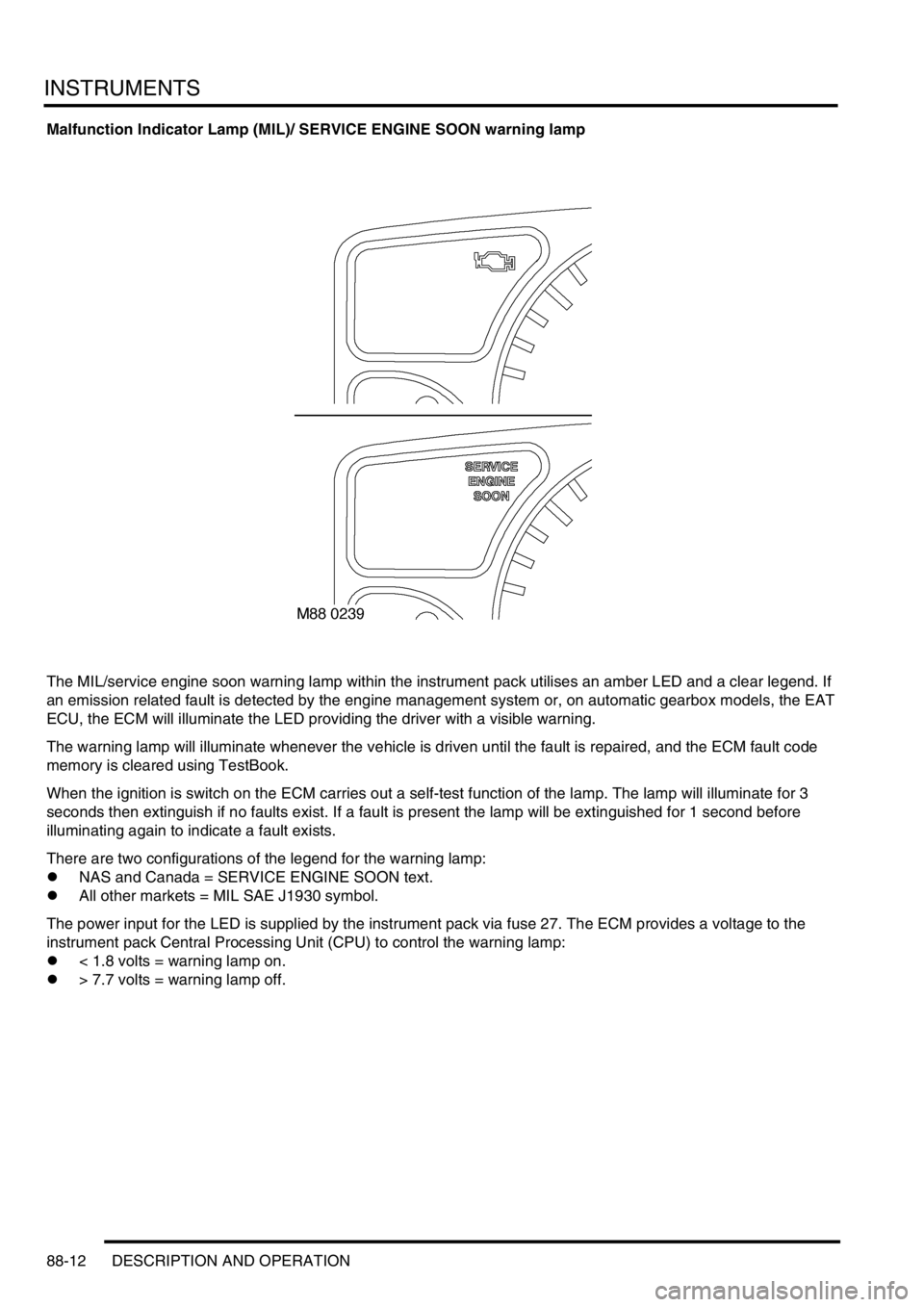
Malfunction Indicator Lamp (MIL)/ SERVICE ENGINE SOON warning lamp
The MIL/service engine soon warning lamp within the instrument pack utilises an amber LED and a clear legend. If
an emission related fault is detected by the engine management system or, on automatic gearbox models, the EAT
ECU, the ECM will illuminate the LED providing the driver with a visible warning.
The warning lamp will illuminate whenever the vehicle is driven until the fault is repaired, and the ECM fault code
memory is cleared using TestBook.
When the ignition is switch on the ECM carries out a self-test function of the lamp. The lamp will illuminate for 3
seconds then extinguish if no faults exist. If a fault is present the lamp will be extinguished for 1 second before
illuminating again to indicate a fault exists.
There are two configurations of the legend for the warning lamp:
lNAS and Canada = SERVICE ENGINE SOON text.
lAll other markets = MIL SAE J1930 symbol.
The power input for the LED is supplied by the instrument pack via fuse 27. The ECM provides a voltage to the
instrument pack Central Processing Unit (CPU) to control the warning lamp:
l< 1.8 volts = warning lamp on.
l> 7.7 volts = warning lamp off.
Page 1515 of 1529
INSTRUMENTS
88-32 DESCRIPTION AND OPERATION
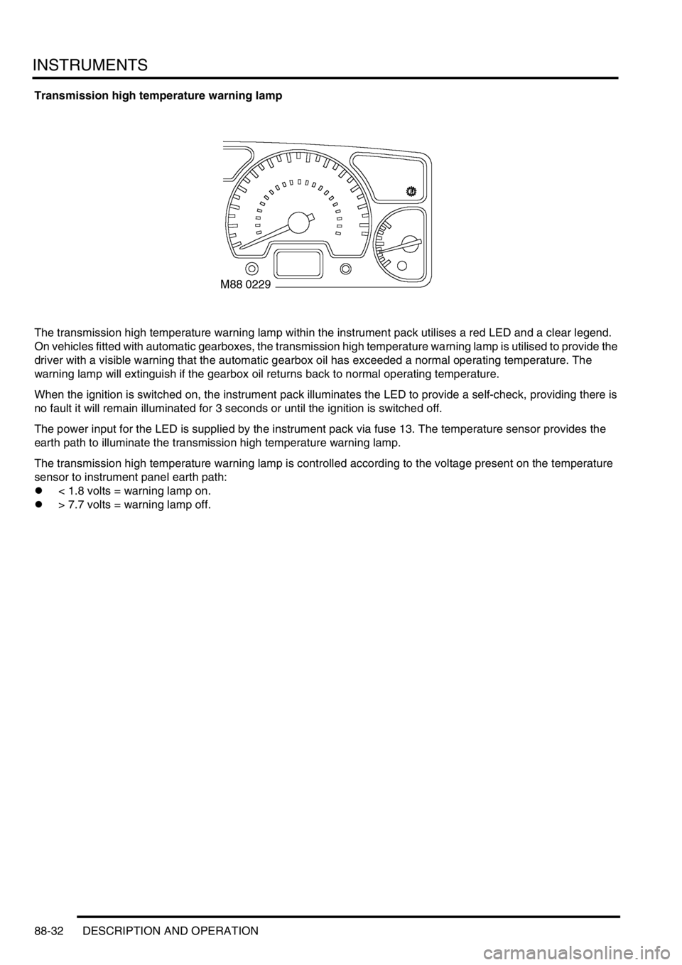
Transmission high temperature warning lamp
The transmission high temperature warning lamp within the instrument pack utilises a red LED and a clear legend.
On vehicles fitted with automatic gearboxes, the transmission high temperature warning lamp is utilised to provide the
driver with a visible warning that the automatic gearbox oil has exceeded a normal operating temperature. The
warning lamp will extinguish if the gearbox oil returns back to normal operating temperature.
When the ignition is switched on, the instrument pack illuminates the LED to provide a self-check, providing there is
no fault it will remain illuminated for 3 seconds or until the ignition is switched off.
The power input for the LED is supplied by the instrument pack via fuse 13. The temperature sensor provides the
earth path to illuminate the transmission high temperature warning lamp.
The transmission high temperature warning lamp is controlled according to the voltage present on the temperature
sensor to instrument panel earth path:
l< 1.8 volts = warning lamp on.
l> 7.7 volts = warning lamp off.
Page 1521 of 1529
INSTRUMENTS
88-38 DESCRIPTION AND OPERATION
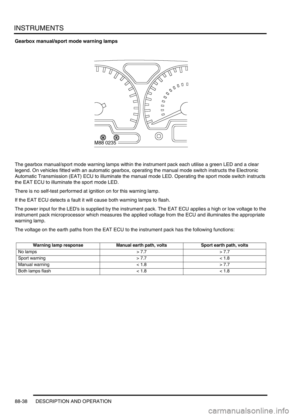
Gearbox manual/sport mode warning lamps
The gearbox manual/sport mode warning lamps within the instrument pack each utilise a green LED and a clear
legend. On vehicles fitted with an automatic gearbox, operating the manual mode switch instructs the Electronic
Automatic Transmission (EAT) ECU to illuminate the manual mode LED. Operating the sport mode switch instructs
the EAT ECU to illuminate the sport mode LED.
There is no self-test performed at ignition on for this warning lamp.
If the EAT ECU detects a fault it will cause both warning lamps to flash.
The power input for the LED's is supplied by the instrument pack. The EAT ECU applies a high or low voltage to the
instrument pack microprocessor which measures the applied voltage from the ECU and illuminates the appropriate
warning lamp.
The voltage on the earth paths from the EAT ECU to the instrument pack has the following functions:
Warning lamp response Manual earth path, volts Sport earth path, volts
No lamps > 7.7 > 7.7
Sport warning > 7.7 < 1.8
Manual warning < 1.8 > 7.7
Both lamps flash < 1.8 < 1.8
Page 1524 of 1529
INSTRUMENTS
DESCRIPTION AND OPERATION 88-41
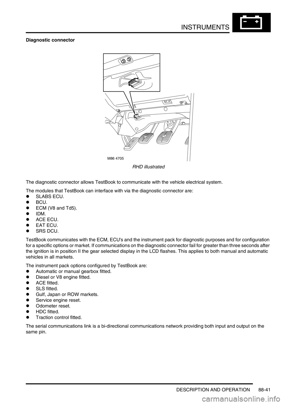
Diagnostic connector
RHD illustrated
The diagnostic connector allows TestBook to communicate with the vehicle electrical system.
The modules that TestBook can interface with via the diagnostic connector are:
lSLABS ECU.
lBCU.
lECM (V8 and Td5).
lIDM.
lACE ECU.
lEAT ECU.
lSRS DCU.
TestBook communicates with the ECM, ECU's and the instrument pack for diagnostic purposes and for configuration
for a specific options or market. If communications on the diagnostic connector fail for greater than three seconds after
the ignition is in position II the gear selected display in the LCD flashes. This applies to both manual and automatic
vehicles in all markets.
The instrument pack options configured by TestBook are:
lAutomatic or manual gearbox fitted.
lDiesel or V8 engine fitted.
lACE fitted.
lSLS fitted.
lGulf, Japan or ROW markets.
lService engine reset.
lOdometer reset.
lHDC fitted.
lTraction control fitted.
The serial communications link is a bi-directional communications network providing both input and output on the
same pin.
M86 4705