1999 LAND ROVER DISCOVERY weight
[x] Cancel search: weightPage 86 of 1529

GENERAL DATA
04-23
Dimensions
* Measurement taken with vehicle at unladen weight.
Overall length - including towing hitch 4715 mm (185.6 in)
Overall length - including spare wheel 4705 mm (185.24 in)
Overall width (excluding mirrors) 1885 mm (74.2 in)
Overall height - Open sunroof * 2015 mm (79.3 in)
Overall height (without roof bars) * 1940 mm (76.40 in)
Minimum ground clearance * 253.5 mm (10.0 in)
Wheelbase 2540 mm (100.00 in)
Turning circle (kerb to kerb) 11.9 metres (39.1 feet)
Track - front 1540 mm (60.63 in)
Track - rear 1560 mm (61.42 in)
Page 87 of 1529

GENERAL DATA
04-24
Weights
NOTE: The rear axle load for vehicles with self levelling suspension can be increased to a maximum of 1928 kg (4249
lb) when towing, provided road speed is limited to 60 mph (100 km/h).
NOTE: Axle weights are non additive. The individual maximum weights and gross vehicle weight must not be
exceeded.
kgs lbs
Unladen weight:
⇒ V8 models 2095 - 2235 4619 - 4928
⇒ Td5 model 2150 - 2280 4740 - 5027
Max.GVW:
⇒ All 5 seat vehicles (coil springs) 2750 6063
⇒ All 7 seat Diesel engine vehicles (coil springs) 2880 6347
⇒ All 7 seat Petrol engine vehicles (coil springs) 2825 6215
⇒ V8 models with self levelling suspension 2825 6228
⇒ Td5 models with self levelling suspension 2880 6349
Max. front axle load 1200 2646
Max. rear axle load:
⇒ With coil springs 1720 3792
⇒ With self levelling suspension 1800 3968
Page 88 of 1529

IDENTIFICATION NUMBERS
05-1
IDE NTIFICATION NUMBERS
Vehicle Identification Number
Location
The Vehicle Identification Number (VIN) plate is
stamped on a plate attached to the bonnet locking
platform. The VIN is also stamped in the following
locations:
lOn a plate behind the LH lower corner of the
windscreen.
lOn the chassis RH longitudinal behind the rear
wheel.
Bonnet locking platform VIN
Windscreen VINChassis VIN
VIN plate content
The VIN plate contains the following information.
aVehicle Identification Number (VIN)
bGross vehicle weight
cGross train weight
dMaximum front axle load
eMaximum rear axle load
fPaint code
gTrim code
Page 186 of 1529
ENGINE - V8
REPAIRS 12-2-31
Flywheel
$% 12.53.07
Remove
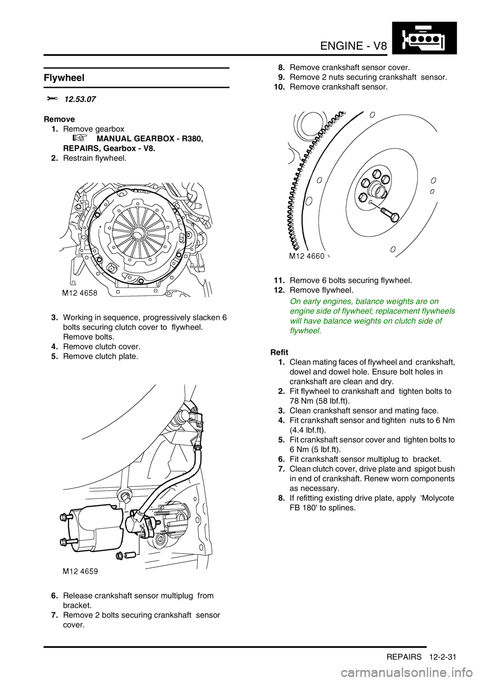
1.Remove gearbox
+ MANUAL GEARBOX - R380,
REPAIRS, Gearbox - V8.
2.Restrain flywheel.
3.Working in sequence, progressively slacken 6
bolts securing clutch cover to flywheel.
Remove bolts.
4.Remove clutch cover.
5.Remove clutch plate.
6.Release crankshaft sensor multiplug from
bracket.
7.Remove 2 bolts securing crankshaft sensor
cover. 8.Remove crankshaft sensor cover.
9.Remove 2 nuts securing crankshaft sensor.
10.Remove crankshaft sensor.
11.Remove 6 bolts securing flywheel.
12.Remove flywheel.
On early engines, balance weights are on
engine side of flywheel; replacement flywheels
will have balance weights on clutch side of
flywheel.
Refit
1.Clean mating faces of flywheel and crankshaft,
dowel and dowel hole. Ensure bolt holes in
crankshaft are clean and dry.
2.Fit flywheel to crankshaft and tighten bolts to
78 Nm (58 lbf.ft).
3.Clean crankshaft sensor and mating face.
4.Fit crankshaft sensor and tighten nuts to 6 Nm
(4.4 lbf.ft).
5.Fit crankshaft sensor cover and tighten bolts to
6 Nm (5 lbf.ft).
6.Fit crankshaft sensor multiplug to bracket.
7.Clean clutch cover, drive plate and spigot bush
in end of crankshaft. Renew worn components
as necessary.
8.If refitting existing drive plate, apply 'Molycote
FB 180' to splines.
Page 188 of 1529
ENGINE - V8
REPAIRS 12-2-33
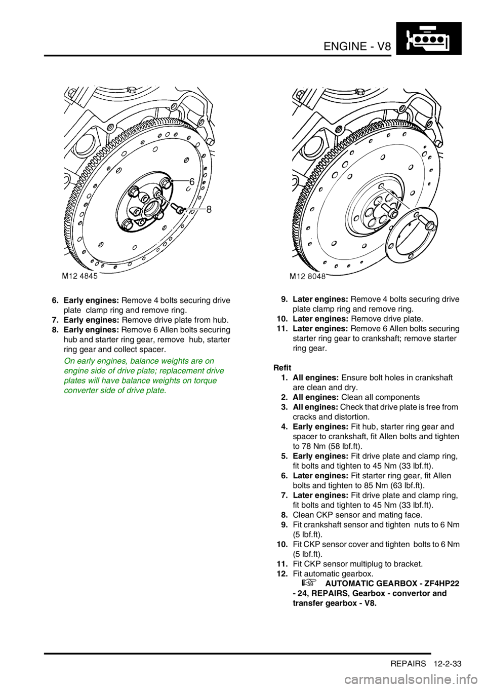
6. Early engines: Remove 4 bolts securing drive
plate clamp ring and remove ring.
7. Early engines: Remove drive plate from hub.
8. Early engines: Remove 6 Allen bolts securing
hub and starter ring gear, remove hub, starter
ring gear and collect spacer.
On early engines, balance weights are on
engine side of drive plate; replacement drive
plates will have balance weights on torque
converter side of drive plate.9. Later engines: Remove 4 bolts securing drive
plate clamp ring and remove ring.
10. Later engines: Remove drive plate.
11. Later engines: Remove 6 Allen bolts securing
starter ring gear to crankshaft; remove starter
ring gear.
Refit
1. All engines: Ensure bolt holes in crankshaft
are clean and dry.
2. All engines: Clean all components
3. All engines: Check that drive plate is free from
cracks and distortion.
4. Early engines: Fit hub, starter ring gear and
spacer to crankshaft, fit Allen bolts and tighten
to 78 Nm (58 lbf.ft).
5. Early engines: Fit drive plate and clamp ring,
fit bolts and tighten to 45 Nm (33 lbf.ft).
6. Later engines: Fit starter ring gear, fit Allen
bolts and tighten to 85 Nm (63 lbf.ft).
7. Later engines: Fit drive plate and clamp ring,
fit bolts and tighten to 45 Nm (33 lbf.ft).
8.Clean CKP sensor and mating face.
9.Fit crankshaft sensor and tighten nuts to 6 Nm
(5 lbf.ft).
10.Fit CKP sensor cover and tighten bolts to 6 Nm
(5 lbf.ft).
11.Fit CKP sensor multiplug to bracket.
12.Fit automatic gearbox.
+ AUTOMATIC GEARBOX - ZF4HP22
- 24, REPAIRS, Gearbox - convertor and
transfer gearbox - V8.
Page 204 of 1529
ENGINE - V8
OVERHAUL 12-2-49
Seal - crankshaft - rear - automatic
models
$% 12.21.20.01
Disassembly
1.Remove CKP sensor.
+ ENGINE MANAGEMENT SYSTEM -
V8, REPAIRS, Sensor - crankshaft position
(CKP).
Note: Later engines are fitted with a modified
starter ring gear which incorporates the reluctor
plate, spacer and hub. The modified ring gear
may be fitted as a replacement to early
engines.
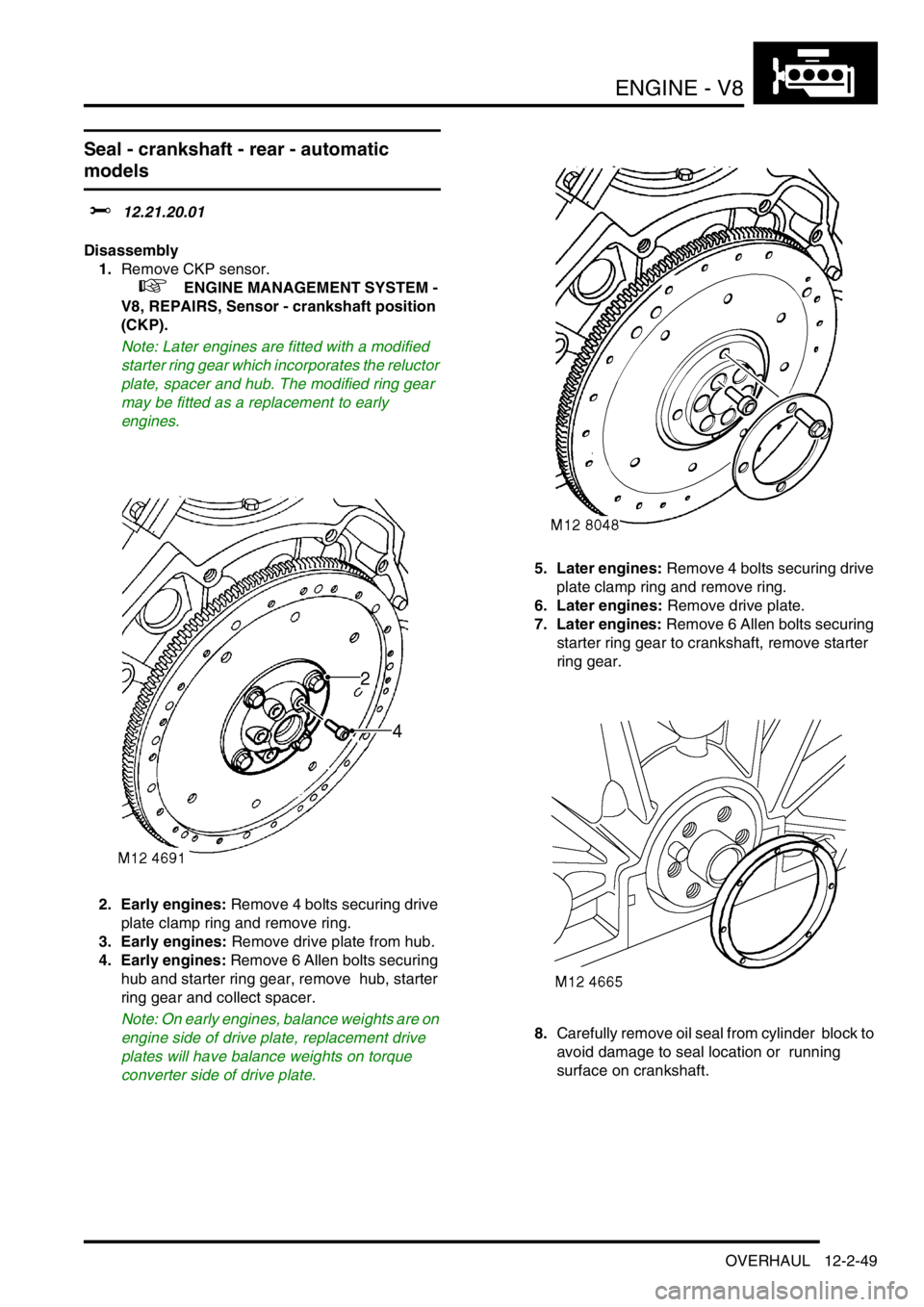
2. Early engines: Remove 4 bolts securing drive
plate clamp ring and remove ring.
3. Early engines: Remove drive plate from hub.
4. Early engines: Remove 6 Allen bolts securing
hub and starter ring gear, remove hub, starter
ring gear and collect spacer.
Note: On early engines, balance weights are on
engine side of drive plate, replacement drive
plates will have balance weights on torque
converter side of drive plate.5. Later engines: Remove 4 bolts securing drive
plate clamp ring and remove ring.
6. Later engines: Remove drive plate.
7. Later engines: Remove 6 Allen bolts securing
starter ring gear to crankshaft, remove starter
ring gear.
8.Carefully remove oil seal from cylinder block to
avoid damage to seal location or running
surface on crankshaft.
Page 401 of 1529
FUEL DELIVERY SYSTEM - V8
19-2-4 DESCRIPTION AND OPERATION
Description
General
The fuel delivery system comprises a fuel tank, fuel pump and regulator and eight injectors. The system is controlled
by the Engine Control Module (ECM) which energises the fuel pump relay and controls the operation and timing of
each injector solenoid.
+ ENGINE MANAGEMENT SYSTEM - V8, DESCRIPTION AND OPERATION, Description - engine
management.
The multiport fuel injection system is a returnless system with the fuel pressure maintained at a constant level by a
fuel pressure regulator. The regulator is located in the fuel pump housing and returns excess fuel directly from the
pump to the tank.
An electrically operated fuel pump is located in the top of the fuel tank and supplies fuel at pressure to two fuel rails
via a flexible hose. The hose is attached to the feed pipe on the fuel rail at the rear of the engine and the fuel pump
with sealed quick release couplings.
A moulded fuel tank is located at the rear underside of the vehicle between the chassis longitudinals. The tank
provides the attachment for the fuel pump and fuel gauge sender unit which is located inside the tank. The fuel system
is pressurised permanently with pressurised fuel vapour venting to an EVAP canister.
+ EMISSION CONTROL - V8, DESCRIPTION AND OPERATION, Emission Control Systems.
Fuel tank and breather
The fuel tank and breather system is a major part of the fuel delivery system. The fuel tank and breathers are located
at the rear of the vehicle between the chassis longitudinals.
Fuel tank
The moulded fuel tank is made from High Molecular Weight (HMW) High Density Polyethylene (HDPE). Continuous
layers of nylon additive are used during the moulding process. The nylon layers give an improved limit of fuel
permeation through the tank wall and are also resistant to alcohol based fuels used in the NAS market.
The tank is retained in position by a metal cradle which is secured to the chassis with two nut plates and bolts at the
rear and a stud plate and two nuts at the front. A strap above the tank is bolted to the chassis and restrains the tank
from moving upwards. The fuel tank has a useable capacity of approximately 95 litres (25 US Gallons).
An aperture in the top surface of the tank allows for the fitment of the fuel pump, regulator and fuel gauge sender unit
which is retained with a locking ring.
A reflective metallic covering is attached to the tank with two scrivets to shield the tank from heat generated by the
exhaust system.
The fuel filler is located in the right hand rear quarter panel, behind an access flap. The flap is opened electrically
using a switch on the fascia.
The filler is closed by a threaded plastic cap which screws into the filler neck. The cap has a ratchet mechanism to
prevent over tightening and seals against the filler neck to prevent the escape of fuel vapour. The filler cap has a valve
which relieves fuel pressure to atmosphere at approximately 0.12 to 0.13 bar (1.8 to 2.0 lbf.in
2) and opens in the
opposite direction at approximately 0.04 bar (0.7 lbf.in2) vacuum.
All markets except NAS: A moulded filler tube, made from HMW HDPE with no additional additives, connects the
filler to the tank via a flexible rubber hose. The filler tube is connected at its top end behind the filler flap.
NAS markets: A fabricated filler tube, made from stainless steel, connects the filler to the tank via a flexible rubber
hose. The filler tube is connected at it's top end behind the filler flap.
On all vehicles that use unleaded fuel, the filler neck is fitted with an inhibitor. The inhibitor is a tapered nozzle in the
mouth of the filler neck which will only allow the use of a standard unleaded fuel filler gun. A spring loaded flap valve
prevents the incorrect fuel from being trickle filled from an incorrect filler gun.
Page 412 of 1529
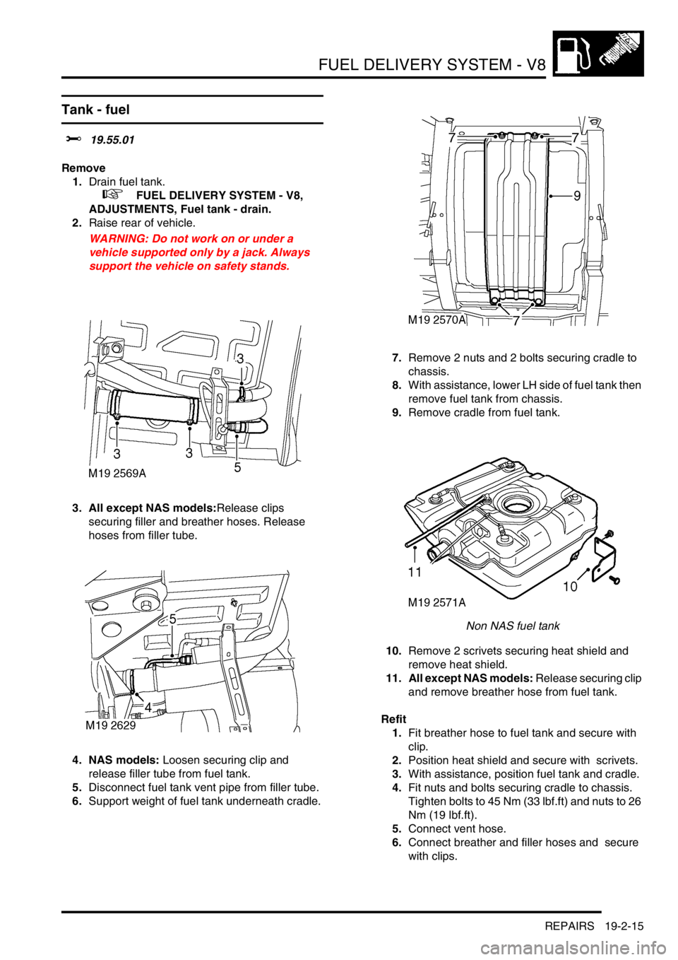
FUEL DELIVERY SYSTEM - V8
REPAIRS 19-2-15
Tank - fuel
$% 19.55.01
Remove
1.Drain fuel tank.
+ FUEL DELIVERY SYSTEM - V8,
ADJUSTMENTS, Fuel tank - drain.
2.Raise rear of vehicle.
WARNING: Do not work on or under a
vehicle supported only by a jack. Always
support the vehicle on safety stands.
3. All except NAS models:Release clips
securing filler and breather hoses. Release
hoses from filler tube.
4. NAS models: Loosen securing clip and
release filler tube from fuel tank.
5.Disconnect fuel tank vent pipe from filler tube.
6.Support weight of fuel tank underneath cradle. 7.Remove 2 nuts and 2 bolts securing cradle to
chassis.
8.With assistance, lower LH side of fuel tank then
remove fuel tank from chassis.
9.Remove cradle from fuel tank.
Non NAS fuel tank
10.Remove 2 scrivets securing heat shield and
remove heat shield.
11. All except NAS models: Release securing clip
and remove breather hose from fuel tank.
Refit
1.Fit breather hose to fuel tank and secure with
clip.
2.Position heat shield and secure with scrivets.
3.With assistance, position fuel tank and cradle.
4.Fit nuts and bolts securing cradle to chassis.
Tighten bolts to 45 Nm (33 lbf.ft) and nuts to 26
Nm (19 lbf.ft).
5.Connect vent hose.
6.Connect breather and filler hoses and secure
with clips.