1999 LAND ROVER DISCOVERY ABS
[x] Cancel search: ABSPage 1155 of 1529

CORROSION PREVENTION AND SEALING
77-4-22 SEALING
Water leaks
Where water leakage is involved, always adopt a logical approach to the problem using a combination of skill,
experience and intuition. Do not reach a conclusion based only on visual evidence, such as assuming that a wet
footwell is caused by a leak emanating from the windscreen. It will often be found that the source of the leak is
elsewhere. Use of the correct procedure will increase the chance of locating a leak, however obscure it may seem.
Tools and equipment
The following tools and equipment are recommended for the purpose of detection and rectification of water leaks:
1Garden sprayer (hand-operated)
2Wet/dry vacuum cleaner
3Dry, absorbent cloths
4Battery torch
5Small mirror
6Weatherstrip locating tool
7Trim panel remover
8Small wooden or plastic wedges
9Dry compressed air supply
10Hot air blower
11Sealer applicators
12Ultrasonic leak detector
During leak detection, the vehicle should be considered in three basic sections:
lThe front interior space;
lThe rear passenger space;
lThe loadspace or boot.
Testing
From the information supplied by the customer it should be possible for the bodyshop operator to locate the starting
point from which the leak may be detected. After the area of the leak has been identified, find the actual point of entry
into the vehicle.
A simple and effective means in the first instance is an ordinary garden spray with provision for pressure and jet
adjustment, which will allow water to be directed in a jet or turned into a fine spray. Use a mirror and a battery-powered
torch (NOT a mains voltage inspection lamp) to see into dark corners.
The sequence of testing is particularly important. Start at the lowest point and work slowly upwards, to avoid testing
in one area while masking the leak in another. For example, if testing started at the level of the windscreen, any water
cascading into the plenum chamber could leak through a bulkhead grommet and into the footwells. Even at this point
it could still be wrongly assumed that the windscreen seal was at fault.
Another important part of identifying a water leak is by visual examination of door aperture seals, grommets and
weatherstrips for damage, deterioration or misalignment, together with the fit of the door itself against the seals.
Sealing
When the point of the leak has been detected, it will then be necessary to rectify it using the following procedure:
1Renew all door aperture seals and weatherstrips which have suffered damage, misalignment or deterioration
2Check all body seals to ensure that they are correctly located on their mounting flanges/faces using a lipping
tool if necessary
3Dry out body seams to be treated using compressed air and/or a hot air blower as necessary
4Apply sealant on the outside of the joint wherever possible to ensure the exclusion of water
5When rectifying leaks between a screen glass and it's weatherstrip (or in the case of direct glazing, between the
glass and bodywork), avoid removing the glass if possible. Apply the approved material at the appropriate
location (i.e. glass to weatherstrip or glass to body)
Page 1193 of 1529
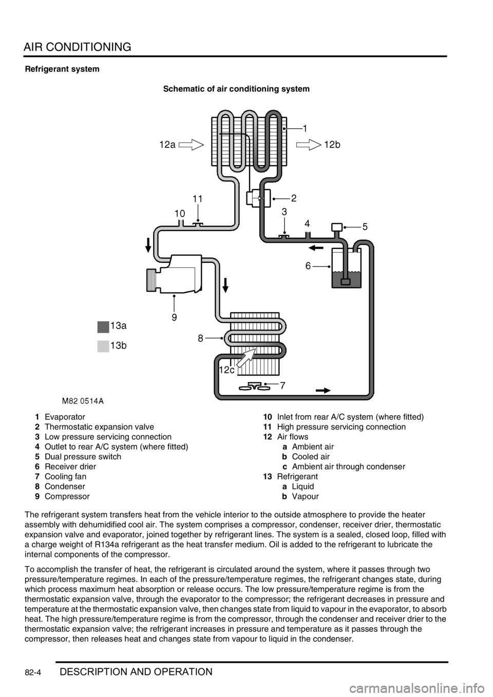
AIR CONDITIONING
82-4DESCRIPTION AND OPERATION
Refrigerant system
Schematic of air conditioning system
1Evaporator
2Thermostatic expansion valve
3Low pressure servicing connection
4Outlet to rear A/C system (where fitted)
5Dual pressure switch
6Receiver drier
7Cooling fan
8Condenser
9Compressor10Inlet from rear A/C system (where fitted)
11High pressure servicing connection
12Air flows
aAmbient air
bCooled air
cAmbient air through condenser
13Refrigerant
aLiquid
bVapour
The refrigerant system transfers heat from the vehicle interior to the outside atmosphere to provide the heater
assembly with dehumidified cool air. The system comprises a compressor, condenser, receiver drier, thermostatic
expansion valve and evaporator, joined together by refrigerant lines. The system is a sealed, closed loop, filled with
a charge weight of R134a refrigerant as the heat transfer medium. Oil is added to the refrigerant to lubricate the
internal components of the compressor.
To accomplish the transfer of heat, the refrigerant is circulated around the system, where it passes through two
pressure/temperature regimes. In each of the pressure/temperature regimes, the refrigerant changes state, during
which process maximum heat absorption or release occurs. The low pressure/temperature regime is from the
thermostatic expansion valve, through the evaporator to the compressor; the refrigerant decreases in pressure and
temperature at the thermostatic expansion valve, then changes state from liquid to vapour in the evaporator, to absorb
heat. The high pressure/temperature regime is from the compressor, through the condenser and receiver drier to the
thermostatic expansion valve; the refrigerant increases in pressure and temperature as it passes through the
compressor, then releases heat and changes state from vapour to liquid in the condenser.
Page 1195 of 1529
AIR CONDITIONING
82-6DESCRIPTION AND OPERATION
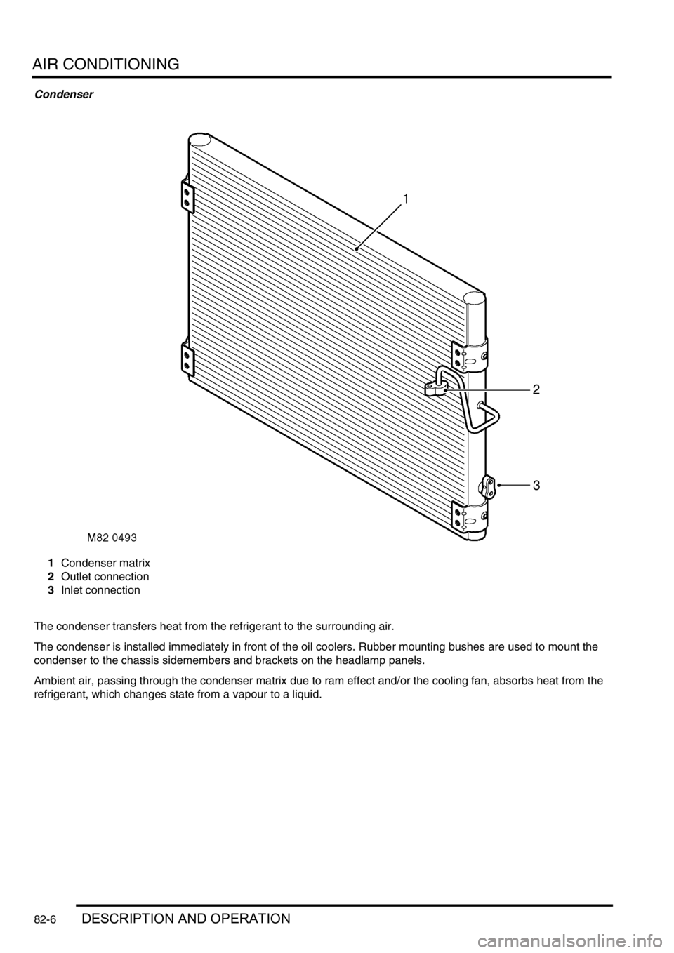
Condenser
1Condenser matrix
2Outlet connection
3Inlet connection
The condenser transfers heat from the refrigerant to the surrounding air.
The condenser is installed immediately in front of the oil coolers. Rubber mounting bushes are used to mount the
condenser to the chassis sidemembers and brackets on the headlamp panels.
Ambient air, passing through the condenser matrix due to ram effect and/or the cooling fan, absorbs heat from the
refrigerant, which changes state from a vapour to a liquid.
Page 1196 of 1529
AIR CONDITIONING
DESCRIPTION AND OPERATION 82-7
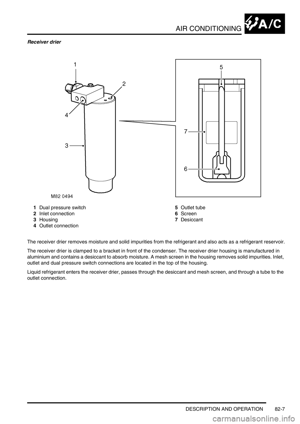
Receiver drier
1Dual pressure switch
2Inlet connection
3Housing
4Outlet connection5Outlet tube
6Screen
7Desiccant
The receiver drier removes moisture and solid impurities from the refrigerant and also acts as a refrigerant reservoir.
The receiver drier is clamped to a bracket in front of the condenser. The receiver drier housing is manufactured in
aluminium and contains a desiccant to absorb moisture. A mesh screen in the housing removes solid impurities. Inlet,
outlet and dual pressure switch connections are located in the top of the housing.
Liquid refrigerant enters the receiver drier, passes through the desiccant and mesh screen, and through a tube to the
outlet connection.
Page 1197 of 1529
AIR CONDITIONING
82-8DESCRIPTION AND OPERATION
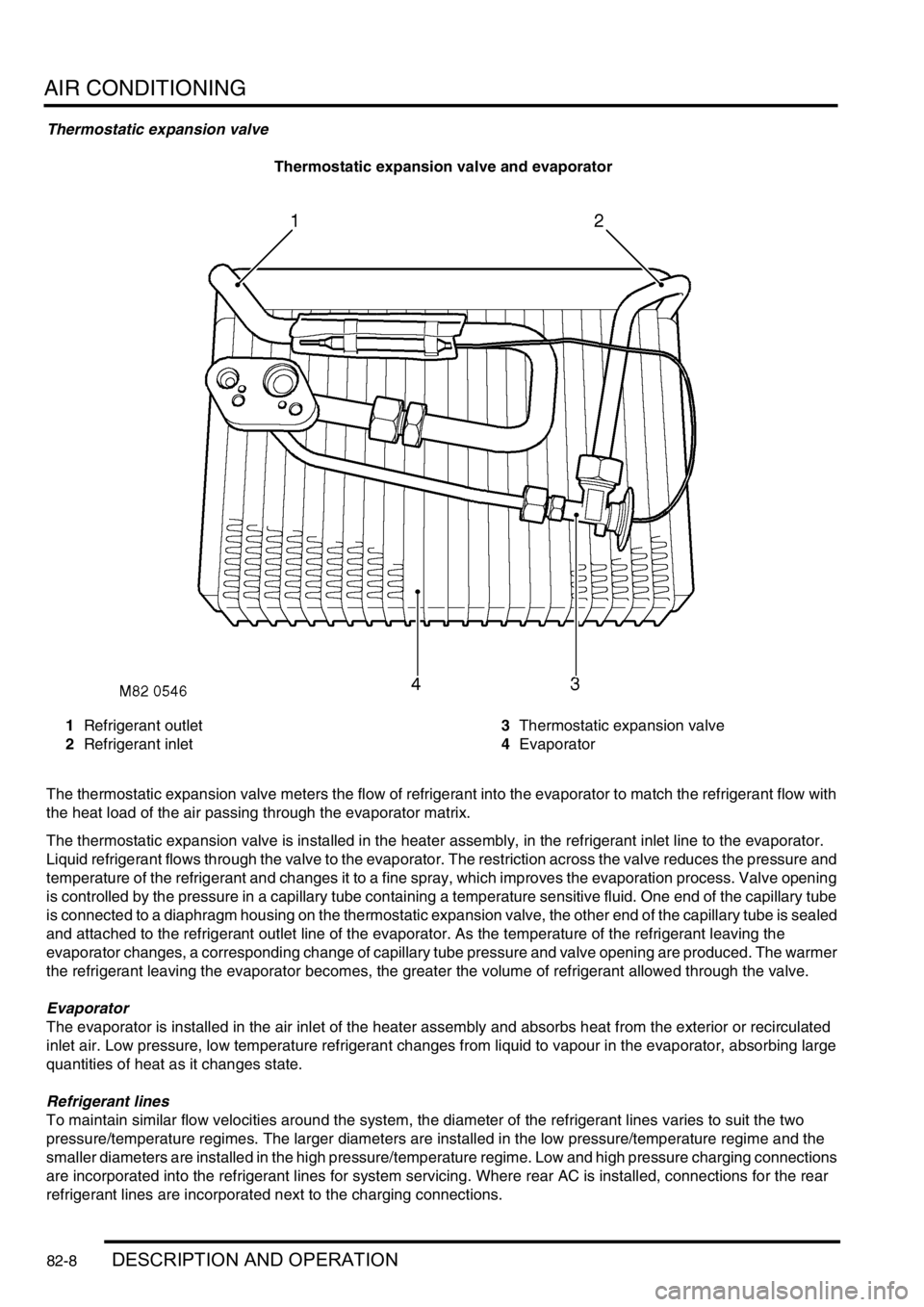
Thermostatic expansion valve
Thermostatic expansion valve and evaporator
1Refrigerant outlet
2Refrigerant inlet3Thermostatic expansion valve
4Evaporator
The thermostatic expansion valve meters the flow of refrigerant into the evaporator to match the refrigerant flow with
the heat load of the air passing through the evaporator matrix.
The thermostatic expansion valve is installed in the heater assembly, in the refrigerant inlet line to the evaporator.
Liquid refrigerant flows through the valve to the evaporator. The restriction across the valve reduces the pressure and
temperature of the refrigerant and changes it to a fine spray, which improves the evaporation process. Valve opening
is controlled by the pressure in a capillary tube containing a temperature sensitive fluid. One end of the capillary tube
is connected to a diaphragm housing on the thermostatic expansion valve, the other end of the capillary tube is sealed
and attached to the refrigerant outlet line of the evaporator. As the temperature of the refrigerant leaving the
evaporator changes, a corresponding change of capillary tube pressure and valve opening are produced. The warmer
the refrigerant leaving the evaporator becomes, the greater the volume of refrigerant allowed through the valve.
Evaporator
The evaporator is installed in the air inlet of the heater assembly and absorbs heat from the exterior or recirculated
inlet air. Low pressure, low temperature refrigerant changes from liquid to vapour in the evaporator, absorbing large
quantities of heat as it changes state.
Refrigerant lines
To maintain similar flow velocities around the system, the diameter of the refrigerant lines varies to suit the two
pressure/temperature regimes. The larger diameters are installed in the low pressure/temperature regime and the
smaller diameters are installed in the high pressure/temperature regime. Low and high pressure charging connections
are incorporated into the refrigerant lines for system servicing. Where rear AC is installed, connections for the rear
refrigerant lines are incorporated next to the charging connections.
Page 1213 of 1529
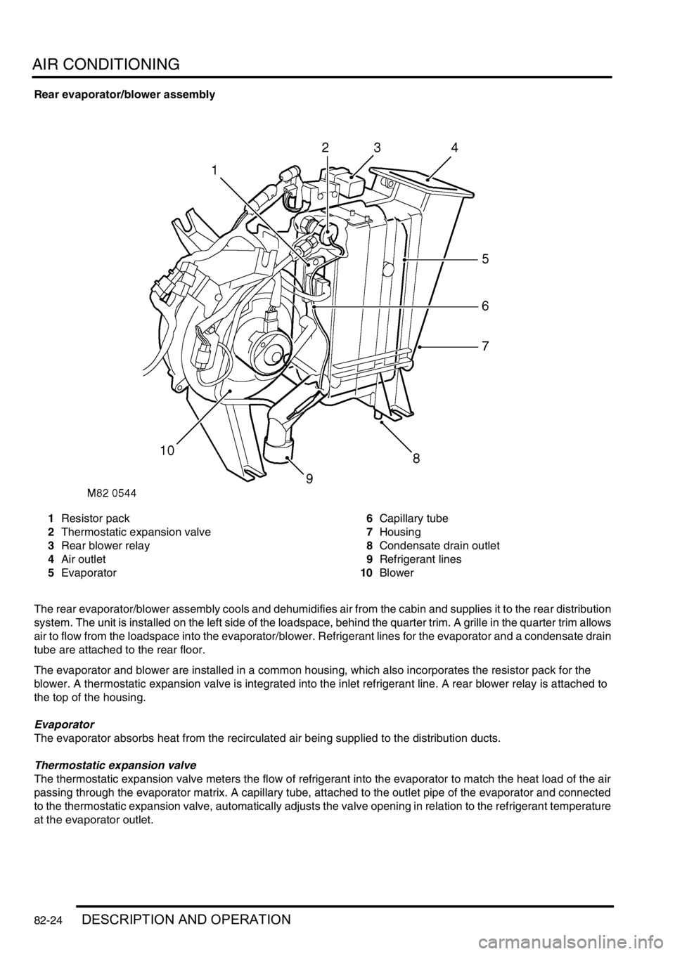
AIR CONDITIONING
82-24DESCRIPTION AND OPERATION
Rear evaporator/blower assembly
1Resistor pack
2Thermostatic expansion valve
3Rear blower relay
4Air outlet
5Evaporator6Capillary tube
7Housing
8Condensate drain outlet
9Refrigerant lines
10Blower
The rear evaporator/blower assembly cools and dehumidifies air from the cabin and supplies it to the rear distribution
system. The unit is installed on the left side of the loadspace, behind the quarter trim. A grille in the quarter trim allows
air to flow from the loadspace into the evaporator/blower. Refrigerant lines for the evaporator and a condensate drain
tube are attached to the rear floor.
The evaporator and blower are installed in a common housing, which also incorporates the resistor pack for the
blower. A thermostatic expansion valve is integrated into the inlet refrigerant line. A rear blower relay is attached to
the top of the housing.
Evaporator
The evaporator absorbs heat from the recirculated air being supplied to the distribution ducts.
Thermostatic expansion valve
The thermostatic expansion valve meters the flow of refrigerant into the evaporator to match the heat load of the air
passing through the evaporator matrix. A capillary tube, attached to the outlet pipe of the evaporator and connected
to the thermostatic expansion valve, automatically adjusts the valve opening in relation to the refrigerant temperature
at the evaporator outlet.
Page 1215 of 1529

AIR CONDITIONING
82-26DESCRIPTION AND OPERATION
Operation
The rear A/C only operates if the front A/C is on to pump refrigerant through the rear evaporator/blower assembly.
When the rear A/C switch is selected on, the indicator lamp in the switch illuminates and the rear blower relay is
energised. The rear blower relay switches battery power to the blower motor, which runs at the speed selected on the
blower speed switch.
The air from the blower passes through the evaporator matrix, which absorbs heat from the air. The cooled air is then
supplied to the roof vents through the distribution ducts. The heat absorbed by the refrigerant in the evaporator is
sensed by the thermostatic expansion valve. The thermostatic expansion valve then opens and regulates the flow of
refrigerant through the evaporator in proportion to the amount of heat being absorbed from the air.
When the rear A/C switch is selected off, the blower stops. The thermostatic expansion valve senses the subsequent
decrease in temperature of the refrigerant in the evaporator. The thermostatic expansion valve then closes and stops
the flow of refrigerant, except for a minimal bleed flow.
Page 1288 of 1529

BODY CONTROL UNIT
DESCRIPTION AND OPERATION 86-3-1
BODY CONTROL UNIT DESCRIPTION AND OPERAT ION
Description
General
The Body Control Unit (BCU) is located behind the passenger glovebox and is connected to the main harness by four
connectors on its bottom edge and an additional connector located on the side of the BCU casing. Mounting the BCU
behind the fascia makes it reasonably inaccessible for intruders to disable the anti-theft system.
The BCU uses solid-state microprocessor control to perform logical operations and timing functions for a variety of
the vehicle's electrically operated systems, these include:
lDoor locking.
lAnti-theft alarm and immobilisation system.
lExterior lighting including direction indicators and hazard warning lamps.
lCourtesy lighting.
lWipers and washers.
lElectric windows and sunroof.
lHeated windows.
The BCU also communicates with several other electronically controlled systems such as the EAT ECU and SLABS
ECU and also has a datalink between the Intelligent Driver Module (IDM) and the instrument pack. The datalink is a
low speed bus capable of transmitting and receiving messages at a data rate of 10,400 bits per second. Additional
inputs and outputs to peripheral devices are included which are necessary for determining vehicle status for particular
logical operations e.g. crank, ignition key inserted, fuel flap enable etc.
The BCU receives its power supply from the engine compartment fuse box, and is protected by a 10 A fuse.
The BCU communicates with the IDM to provide the control signals to perform power switching operations in
conjunction with dedicated relays.
IDM
The IDM is integrated into the passenger compartment fuse box, which is mounted behind the fascia below the
steering column. There are no harnesses between the fuse box and the IDM. The IDM performs the power switching
operations for several of the vehicle's electrical systems.
The IDM communicates with the BCU and the instrument pack via a serial interface. If the BCU or the IDM is replaced,
the communications link between the two units has to be re-established. This can be done either by switching on the
ignition and leaving it on for five minutes, or by using TestBook. The vehicle immobilisation will remain active until the
communications link between the BCU and IDM has been re-established.
Transit mode
To prevent excessive battery drain during transit to overseas markets, the vehicle is placed in a transit mode. The
following functions are disabled when the vehicle is in transit mode:
lVolumetric sensors.
lPassive immobilisation.
lImmobilisation of the vehicle by use of door lock.
lIgnition key interlock.
lElectric seat enable time-out with driver's door open.